Control circuit connections
Control circuit terminals features⚓
Screw type | M3 |
|---|---|
Tightening torque | 0,5 Nm ... 0,6 Nm 4.42 in-lbs ...5.31 in-lbs |
Conductor stripping length | 7 mm 0.28 in |
Solid conductor cross-section | 0,2 mm² ... 2,5 mm² AWG 24 ... 14 |
Flexible conductor cross-section with Ferrule | 0,25 mm² ... 2,5 mm² AWG 23 ... 14 |
2 Solid conductors with the same cross-section | 0,2 mm² ... 1 mm² AWG 27 ... 14 |
2 Flexible conductors with same cross-section | 0,2 mm² ... 1,5 mm² AWG 27 ... 15 |
Digital input terminals⚓
Marking | Name | Default Operation |
|---|---|---|
1 | Digital input 1 | Reserved for encoder, phase A. Default setting: unused |
2 | Digital input 2 | Reserved for encoder, phase B. Default setting: unused |
3 | Digital input 3 | Run forward |
4 | Digital input 4 | Run Reverse |
5 | Digital input 5 | Stop |
6 | Digital input 6 | Select reference speed between preset 1 and analog input 1 |
+24 | Common terminal for digital inputs |
Relays output terminals⚓
Group | Marking | Name | Default Operation |
|---|---|---|---|
Relay 1 | C | Common of the contacts | Relay 1 (SPDT) is assigned by default to be the alarm relay. The relay is energized when there is no alarm present (C and NO connected). The relay is de-energized when there is an alarm or a loss of power supply (C and NC connected) |
NO | Normally opened contact | ||
NC | Normally closed contact | ||
Relay 2 | C | Common of the contact | Relay 2 (NO) is factory default set to be closed when the drive is in the state “ready to run” |
NO | Normally opened contact | ||
Relay 3 | C | Common of the contact | Relay 3 (NO) is factory default set to be closed when the drive is in the state “running” |
NO | Normally opened contact | ||
The operation of the 3 independent relay outputs of the Clean Power VFD can be set by the user. The settings are described in the section Functions and Parameters .
Always protect relay outputs from inductive load damage, using an appropriate external protective circuit or device.
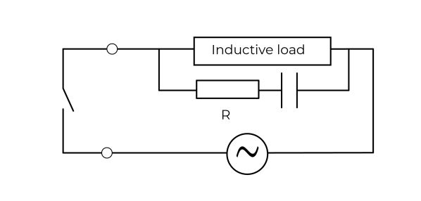
C: capacitor from 0.1 to 1 μF.
R: resistor of approximately the same resistance value as the load.
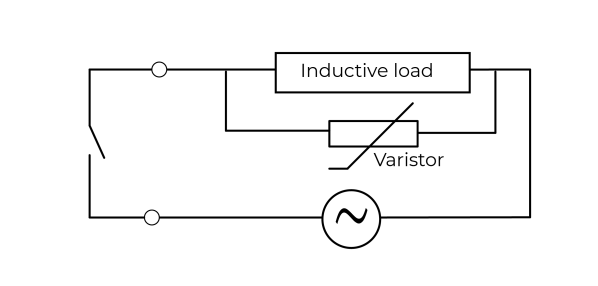
In applications where the inductive load is switched on and off frequently and/or rapidly, ensure that the continuous energy rating (J) of the varistor exceeds the peak load energy by 20 % or more.
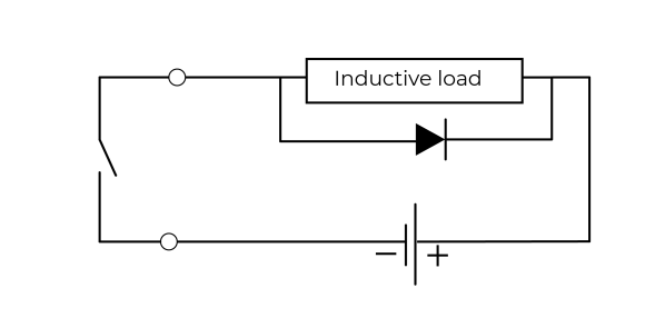
Use a diode with the following ratings:
Reverse withstand voltage: power voltage of the load circuit x 10.
Forward current: more than the load current.
STO terminals⚓
The Safe Torque Off (STO) enabling-terminals are positive logic input only.
The user is responsible for ensuring that the complete system is safe and designed correctly according to the relevant safety standards.
If the Safe Torque Off function is not required, the terminals STO1 and STO2 must remain connected to the terminal +24.
Mark | Name | Default settings |
|---|---|---|
STO1 | Safe torque off - input 1 | Open: STO is enabled and the Clean Power VFD output is de-energized. Closed: STO is disabled and the Clean Power VFD is in normal operation Note: Remove the jumper between STO1 and +24V during the use of the safety deactivation input. The length of the wire should not exceed 30 m (98.4 ft). |
STO2 | Safe torque off - input 2 | Open: STO is enabled and the Clean Power VFD output is de-energized. Closed: STO is disabled and the Clean Power VFD is in normal operation Note: Remove the jumper between STO2 and +24V during the use of the safety deactivation input. The length of the wire should not exceed 30 m (98.4 ft). |
+24 | Safe torque off - power supply |