Control Circuit description
Control Circuit Connection Diagram and functions⚓
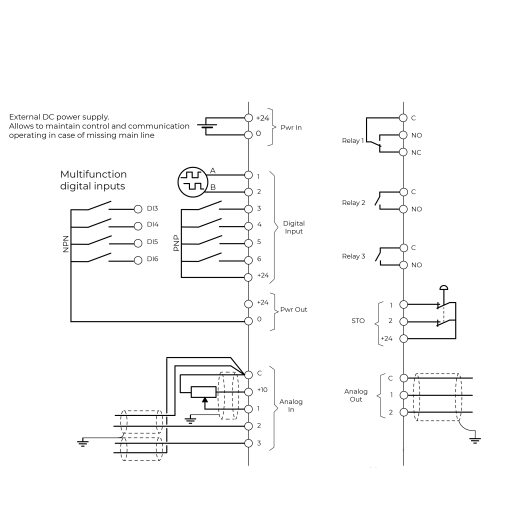
The illustration below shows the detailed layout of control wiring terminals.
Ensure that the cables selected meet or exceed the specifications.
24VDC power in⚓
A 24VDC external power supply can be connected to the terminals Pwr In (terminals +24VC and 0).
The 24VDC auxiliary supply will power the Clean Power VFD control board in the absence of line power, allowing both communications and the HMI to continue to operate.
If a 24VDC is used while commissioning the Clean Power VFD and line power is absent, the Clean Power VFD will be in the under-voltage alarm state.
Ensure to use a DC power supply that meets the following specifications:
Nominal operating voltage | 24 | V |
|---|---|---|
Minimum continuous operating voltage | 19.2 | V |
Maximum continuous operating voltage | 28.8 | V |
Maximum power supply requirement at 24V | 50 | W |
Recommended protection fuse | 4A - 50 VDC | |
24VDC power out⚓
Clean Power VFD provides the user with a 24VDC power out on the terminals Pwr Out (terminals +24VC and 0).
This power is used to energize the digital inputs.
Ensure that the maximum current level, as defined in the table below, is respected.
Nominal operating voltage | 24 | V |
|---|---|---|
Minimum continuous operating voltage | 19.2 | V |
Maximum continuous operating voltage | 28.8 | V |
Maximum output current at 24V | 200 | mA |
Recommended protection fuse | 4A - 50 VDC | |
Sinking Mode/Sourcing Mode.⚓
Digital inputs DI11 to DI6 can be wired either in Source (PNP) or Sink (NPN) mode.
Selection is made by settings in the software.
By default, the digital inputs are set to be wired in Source (PNP) mode.
Note, you can not mix source and sink wiring modes, all inputs from DI3 to DI6 must be wired in the same mode.
In this first version, only Source (PNP) mode is available