Equalizer
Overview
An equalizer can be used to give you control over different parts of the frequency spectrum, independently allowing you to make character or corrective alterations by applying additive EQ or subtractive EQ.
Module Interface

| Label | Section | Controls and Features |
|---|---|---|

|
Meters and Displays | Spectrum Analyzers, Composite Curve, Filter Response Curve, Meter Scales |

|
Module Header | Scale, Soft Saturation, Learn Reset |

|
Controls | Nodes, HUD Controls: General Band Controls, Filter Shapes, Readouts |
Meters
The following meters and displays are included in the EQ:

| Label | Section |
|---|---|
|
|
Spectrum Analyzers |
|
|
Composite Curve |
|
|
Filter Response Curve |

|
Meter Scales |
Spectrum Analyzers
Displays the magnitude (amplitude, in decibels) of the input signal across the frequency spectrum in real-time. Two spectrum analyzers are displayed in the EQ module to compare the effect of processing.
- Input signal: The input signal to the EQ module is shown as a dark grey spectrum with no border.
- Output signal: The processed output spectrum is drawn in the foreground with a white border.
Composite Curve
Displays the combined filter response of all enabled bands. Represented by a thick white line drawn across the display. Adjusting EQ nodes will contribute to the overall shape of the composite curve.
Filter Response Curve
Displays the filter response of the currently selected node. Represented by a highlighted line and filled area under the band which appears when you select a node. If there are no nodes selected, the filter response curve is hidden and you will only see the composite curve.
Meter Scales
The Meter Scales are located on the left, right, and bottom of the spectrum window display. You can use these meter scales as a reference while making adjustments.
- Gain Scale (dB): displayed on the right side of the spectrum window.
- Spectrum Magnitude Scale (dB): displayed on the left side of the spectrum window.
- Spectrum Frequency Scale (Hz): displayed along the top of the spectrum window.
You can change the Frequency Scale measurements through the Scale menu, located in the Module Header or in Options under the EQ tab. Choose one of the Frequency Scale options to help you see different frequency distributions when placing your EQ nodes. The default scale is Extended Log.
| SCALE TYPE | DESCRIPTION |
|---|---|
| LINEAR | Displays an even view across all frequencies. This scale emphasizes the higher frequencies which can be useful for dialing in ‘air’ bands or EQ brightness. |
| MEL | Displays a frequency scale based on human perception of sound that visually corresponds to how we hear differences in pitch. |
| LOGARITHMIC, (FLAT, EXTENDED) LOGARITHMIC | Displays non-linear scales that offer detail on the low end and midrange, useful for the vast majority of EQ tasks. |
| PIANO ROLL | Uses default Extended Logarithmic scale while displaying a Piano Roll at the bottom of the EQ display to show the frequency and musical note relation. |
TIP: Use Piano Roll to Make EQ Decisions
You can use Piano Roll Frequency Scale to help make EQ decisions based on the musical range of the source material. This can help ensure that you’re not removing or reducing frequencies important to the musical structure of the instrument part.
Module Header
The controls in the module header affect the overall resulting EQ module signal processing, but does not affect an individual band. The image and table below outline the controls in the Module Header.

| Label | Section |
|---|---|
|
|
Scale |
|
|
Soft Saturation |
|
|
Learn |
|
|
Reset |
Scale
Select an EQ frequency scaling option from the Scale Menu. See Meter Scales section for more information.
Soft Saturation
Enable Soft Saturation mode to excite the input signal generating subtle harmonics resulting in a fuller sound and subtle coloration by your EQ shaping.
Learn
Enable Learn to quickly have EQ node placement suggestions based on intelligently identified areas of sonic importance in your audio signal such as sibilance, resonance, and rumble.
TIP: Learn Function Only On Enabled Bands
Learn will never remove or create an EQ band. Learn will only suggest adjustments for bands that are already present in the EQ module. Learn suggestions also do not affect Gain or Q. Once nodes are placed, you can hold the SHIFT key to preserve the frequency placement, and then move the gain up or down to determine if your track sounds better with that specific area of interest boosted or cut.
TIP: Learn Function As Starting Point in EQ
Use Learn as a starting point to quickly begin equalizing with its unique adaptive suggestions based on the sonic profile of your audio.
Reset
Returns all controls in the Equalizer module to their factory default values. If you wish to return to settings you were using before clicking the Reset button, you can use the Undo History window to revert to the settings before the Reset event.
Controls
Node Interactions
You can adjust bands by adding or removing nodes.
ADD NODES
You can add bands in three different ways:
- Add on the Composite Curve: Hover over the white composite curve for a + button to appear. Click on the + button to add a node at the specific frequency on the composite curve.
- Add with Keyboard Shortcut: Hit command+return (Mac) or ctrl+return (Windows) to add a new node to the center of the EQ spectrum.
- Add anywhere on the Spectrum: Double-click anywhere in the EQ spectrum to add a new node at the location of the mouse.
NOTE: NODES WILL ADD CONTEXTUAL FILTER SHAPE
Depending on where you add a node, the node will appear with a pre-determined filter shape. There are three default contextual filter shapes that will be used when you add a new node:
- To the far left: Flat Highpass or High Shelf
- To the far right: Flat Lowpass or Low Shelf
- In the middle: Proportional Q
The Flat High Pass and the Flat lowpass will only be added once because you will typically only use one of each in either end of the spectrum. Otherwise, the node will default to a Shelf or Proportional Q filter shape.
REMOVE BANDS
You can remove bands in three different ways:
- Remove Single band: Select a node and click the X button in the HUD to remove it.
- Remove Multiple bands: Click and drag to select multiple nodes. Use the delete or backspace key to remove all selected nodes.
- Remove with modifier keys: SHIFT-click to select multiple nodes. Use the delete or backspace key to remove all selected nodes.
HUD Controls
You can access a band’s HUD by selecting the band’s node. The HUD includes:
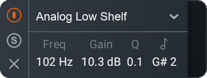
General Band Controls
The left side of the HUD includes parameters for enabling/disabling, soloing, and removing the currently selected band.
| Icon | Control | Description |
|---|---|---|

|
Power Button | Enables or disables processing of the currently selected band. |

|
Solo | Enables the selected filter to be listened to in isolation. |

|
Remove | Removes the band. |
NOTE: Bypassed filter response curve display
When a band is disabled, the filter response curve will still be displayed in the EQ module panel. Disabled bands are displayed in grey to clearly differentiate them from enabled bands.
NOTE: Using Alt-Solo and Band Solo
Use the following methods to solo a specific band or area of the frequency spectrum:
- Band Solo: Filters per-band. To access Band Solo, alt ( option) key and click on a node to solo the band. You can also use the Solo button in the HUD display to solo the selected band.
- Alt-Solo: Creates a moveable filter window allowing you to easily focus on the frequencies surrounding the location of the click. To access Alt-Solo hold the alt ( option) key and click anywhere on the frequency spectrum.
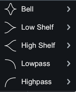
Band Filters
Use the image below to refer to the types of filters and associated filter shapes in the Filter Shape menu.
Filter Types
Filter Types
The EQ module features 13 different filter shapes, each one belonging to one of the following filter type categories: Pass Filter, Peak Filter, Shelf Filter.
| Filter Type | Description |
|---|---|
| Pass Filter | Used to attenuate frequency content that is below (for highpass) or above (for lowpass) a specified cutoff frequency. In the Lowpass and Highpass menu: Flat, Resonant. |
| Peak Filter | Used to boost or cut a specific center frequency level. In the Bell menu: Bell, Proportional Q, Band shelf. |
| Shelf Filter | Used to boost or cut the frequency content above or below a specified frequency. In the Low Shelf menu and High Shelf menu: Analog, Vintage, Baxandall. |
NOTE: Filters Dependent on Slope/Q Adjustments
Adjustment to the bandwidth (Q value) will determine the amount of boost/cut applied to frequencies around the center frequency. The slope of the filter defines the degree of applied attenuation.
Filter Shapes
Choose from the Filter Shape menu to assign the filter shape of the selected band. The filter shape dropdown menu organizes the filter shapes into the following sub-menus: Bell, Low Shelf & High Shelf, and Lowpass & Highpass.
Bell
The Bell sub-menu includes the following Peak type filters:
| Shape | Description | When to Use |
|---|---|---|
Proportional Q(default)

|
Unique filter that varies shape in proportion to the amount of boost or cut applied. As you increase or decrease the gain, the change is proportional to bandwidth where you will see the shape of the curve tightens with more extreme values of gain. | Tight, precise corrective cuts-the bigger gain adjustment, the tighter the cut will become. |
Bell

|
Smoothly boosts or cuts an adjustable region around a specific frequency. Looks like a bell, come on what do you want from me. | At larger gain adjustments (boost or cut), will change the overall color or texture of the sound. This will be a more noticeable change than Proportional Q. |
Band shelf

|
Bell filter with wide, flat top. | To change the relation between the harmonics in your audio. Useful for boosting or attenuating a block of frequencies. |
Low Shelf and High Shelf
The Low Shelf sub-menu and High Shelf sub-menu includes the following Shelf type filters:
| Shape | Description | When to Use |
|---|---|---|
Analog

|
Efficient shelf filter for simple boosts and cuts. Similar to standard shelf in an analog EQ. | To make noticeable boosts for making large changes in how bright or how bassy the content is. |
Baxandall

|
Inspired by the Baxandall EQ, with the addition of freely adjustable frequency.Low shelf: Gentle low frequency shelf.High Shelf: Gentle high frequency shelf. | Transparent way of addressing extreme lows and extreme highs for a more natural, gentle sounding effect. |
Vintage

|
Inspired by the renowned Pultec analog equalizer. Exhibits a complementary frequency dip, creating a complex slope with one node. | To fatten up low end without introducing muddiness. |
Lowpass and Highpass
The Lowpass sub-menu and Highpass sub-menu includes the following Pass type filters:
| Shape | Description | When to Use |
|---|---|---|
Flat

|
Butterworth filter; optimized for maximum flatness without ripple or resonance in the passband or stopband (stability). | To transparently remove low end or high end frequency information without disturbing the character of the signal. Provides a clean, even, and natural sound. |
Resonant

|
Filter equipped with a resonance control to emphasize the cutoff frequency with positive gain. | Boosting content at the cutoff frequency to add character and emphasize the lowest or highest part of the signal. |
NOTE: Gain and Q Adjustments
Baxandall filter shape does not allow for Q adjustment. Lowpass and highpass filter shapes do not allow for Gain adjustments. For these filters, the Q or Gain settings will be disabled or hidden.
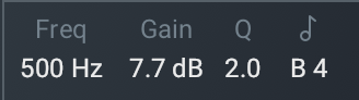
Readouts
Use the HUD Readouts to see and adjust where the node is located within the EQ. The table below describes the readouts available with each readout’s respective Units.
| Readout | Units | Description |
|---|---|---|
| Frequency | Hz | Shows the center frequency (or cutoff frequency) of the currently selected node. The EQ supports frequency values ranging from 20 Hz to 20 kHz. |
| Gain | dB | Shows the amount of gain applied by the selected filter. The EQ supports gain adjustments ranging from -30 dB to +15 dB. |
| Q(Parametric/Bell Filters) | (cF/Bandwidth) | Shows the width or slope of the selected filter. |
| Slope(Highpass/Lowpass Filters) | (dB/octave) | Shows the cutoff slope of the filter. |
| Pitch | Note | Shows where the node is on the frequency spectrum in relation to the musical note. |
Adjust Frequency, Gain, and Q
There are 3 ways to adjust the Frequency, Gain, and Q:
- Click and drag EQ node or handles (for Q only).
- Manually enter the value.
- Use arrow keys.
Below outlines the three types of adjustments you can apply for altering the Frequency, Gain, and Q values.
| Value | Types of Adjustments |
|---|---|
| Frequency | Click and drag EQ node left to decrease the frequency or right to increase the frequency. Manually enter the value as described below. Use LEFT and RIGHT arrow keys. |
| Gain | Click and drag EQ node down to decrease the gain or up to increase the gain. Manually enter the value as described below. Use UP and DOWN arrow keys. |
| Q | Click and drag EQ node handles toward node to narrow the bandwidth or away from the node to widen the bandwidth.Manually enter the value as described below. Use alt/ option + arrow keys. |
To manually enter the value for Frequency, Gain, or Q:
- Double click on the value readout of the metric you wish to change.
- Type in the value desired in the text edit field.
- Hit enter or return to save the value adjustment.
TIP: Keyboard Modifiers For Value Adjustments
- Hold Shift key while clicking and dragging the node to lock the movement to the horizontal axis (for frequency) and vertical axis (for gain).
- Hold Shift while using the arrow keys to make coarse value adjustments.
- Hold the command key (Mac) or ctrl key (Windows) while using the arrow keys to make fine value adjustments
NOTE: Reset All Band Parameters
You can reset all parameters for a particular band to their default values by double clicking on the node.
NOTE: EQ Gain Scale
Use the EQ Gain scale, located on the right edge of the EQ module display to reference dB magnitude while adjusting nodes.