Global Controls
Overview
The Module Chain and I/O section include a number of parameters for customizing the IPC instance name, signal flow, levels, and stereo image of Nectar 3.
Resizable Window
Nectar 3 features a resizable main window. The window can be resized by clicking and dragging the bottom right corner of the plug-in window.
Plug-in Instance Name
Determines the name of the current instance when it appears in IPC lists in supported iZotope plug-ins.

Module Chain
The Module Chain allows for highly customizable vocal processing chains.
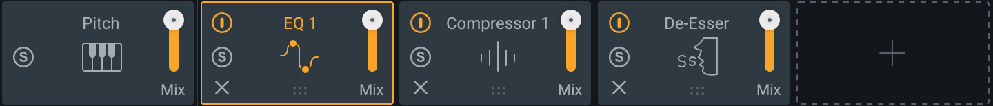
The following modules can be added to the module chain:
- Compressor (x2)
- De-esser
- Delay
- Dimension
- EQ (x2)
- Gate
- Harmony
- Pitch
- Reverb
- Saturation
The following functions and controls are available in the module chain:
Add
Clicking the + button in the rightmost position of the module chain will open the module menu. Select a module from the list to add it to the last slot in the module chain.
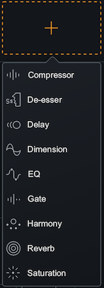
Module Limits
Most modules can only be added to the module chain once. If a module has been added to the module chain already, the option in the module list will be greyed out. Only the EQ and Compressor modules can be added to the module chain twice.
Reorder
Click and drag a module panel left or right within the Module Chain to change its order in the signal flow.
Pitch Module
The Pitch module is always present in the first position of the Module Chain. It cannot be removed or reordered. See the Pitch chapter for more information about the Pitch module.
Enable
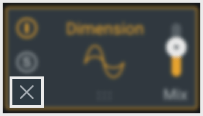
Click the power button the upper left corner of a module tile to bypass processing of that module.

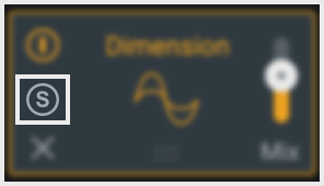
Solo
Click the S button on the left side of a module tile to bypass processing in all other modules.
Remove
Click the X button on the left side of a module tile to remove the associated module from the module chain.
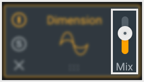
Mix
The slider on the right side of a module tile adjusts the balance between the dry (unprocessed) and wet (processed) signals.
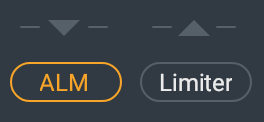
ALM (Auto Level Mode)
The ALM button above the input level meter enables or disables ALM (Auto Level Mode) processing.
When enabled, ALM will adjust input gain in order to hit the ALM target level. ALM looks at the RMS level of the input signal, when that level is within 3dB (above or below) of the target level, it will dynamically adjust the input gain up or down in order to match the it to the target level.
ALM will only ever add or subtract 3dB of gain from the input, so if the RMS level of the input is 3 dB or more below the target, it will add 3dB of gain to the input. If the RMS input level is 3dB more above the target, it will lower the gain of the input by 3dB.
Input Level Meter
When ALM is enabled, The input level meter will display the input signal after ALM processing has been applied to the input signal.
ALM Target Level
Adjusts the ALM target level when ALM is enabled.

Tips: Adjusting ALM Target
The ALM Target Level can be adjusted using the following methods:
- Click and drag the slider handle up (increase target level) or down (decrease target level).
- Click on the slider handle and then click on the text readout display that appears. Manually enter an ALM Target in the inline edit field.
Limiter
Enables a brickwall, zero latency limiter on the output signal. The Limiter is applied to the signal after output gain.

Ceiling
Determines the maximum output level of the plug-in when the limiter is enabled.

The hard limiter uses the Ceiling as an absolute guide, and the final output level will not exceed this point.
Tips: Adjusting the Limiter Ceiling
The Limiter Ceiling can be adjusted using the following methods:
- Click and drag the slider handle up (increase ceiling level) or down (decrease ceiling level).
- Click on the slider handle and then click on the text readout display that appears. Manually enter a Ceiling value in the inline edit field.
Gain Reduction Meter
Displays the amount of gain reduction applied to the output signal by the Limiter.

Input and Output
Meters
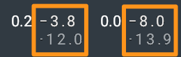
The Input and Output meters display Peak and RMS metering information. The Peak level meter is displayed in white. The RMS level meter is displayed in grey.
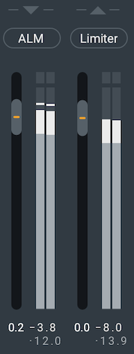
The text readouts directly below the meters display the current Peak and RMS values. The current Peak value is displayed in white. The current RMS value is displayed in light grey.
Gain
The Input and Output Gain can be adjusted using the sliders to the left of the input and output meters.

Tips: Adjusting the I/O Gain
The Input and Output Gain can be adjusted using the following methods:
- Click and drag the slider handle up (increase input or output gain) or down (decrease input or output gain).
- Double-click on the text readout directly below the gain sliders and manually enter a gain value in the inline edit field.
Bypass
Bypasses all processing applied by Nectar 3.

Match
When Nectar 3 is bypassed and Match is enabled, the bypassed signal level will be adjusted to match the processed output level.

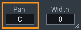
Width
Adjusts the amount of stereo widening. Decreasing this control results in a narrowing effect (-100% is equivalent to mono), increasing this control widens the apparent stereo field.
Stereo Instances Only
Width is only functional in stereo instances of Nectar.
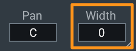
Pan
Pans the output signal to the left or right channel.
Stereo Instances Only
Pan is only functional in stereo instances of Nectar.