EQ
Overview
An equalizer can be used to enhance the tone and character of a vocal track by adjusting the level of specific frequencies. Nectar 3 includes two EQ modules with support for adding up to 24 highly customizable bands. Each band includes 16 different filter shapes and two program dependent processing modes: Dynamic Frequency mode for dynamically updating the frequency of a filter in response to harmonic frequency content changing over time, and Dynamic Gain mode for dynamically adjusting the gain of a filter in response to the input signal.

Interactions
Add Bands
Bands can be added to the EQ using the following methods:
- Click on the + button that appears when hovering the mouse cursor over the white composite
curve line in the EQ display.
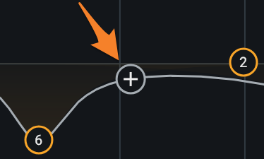
- Single-click to place a new node in the location of the click.
- Click and drag on the + button to quickly add a node and drag it to a new position.
- Double-click anywhere in the EQ spectrum display to add and position a new node in the location of the click.
- Double-click and drag to quickly position the node in the location of the click, and drag it to a new position.
- Use Command+Return (Mac) or Control+Return (Windows) to add a new node to the center of the EQ spectrum.
Remove Bands
Bands can be removed from the EQ using the following methods:
- Select a node and click the x button in the band controls panel to remove it.
- Click and drag over nodes in the EQ spectrum panel to select multiple nodes. Use the delete or backspace key to remove all selected nodes.
- Shift-click to select multiple nodes. Use the delete or backspace key to remove all selected nodes.
Alt-Solo
The EQ module includes an Alt-Solo feature that allows frequency bands to be played back in isolation without affecting any EQ settings.
Alt-Solo can be enabled by holding the Alt/option key when clicking anywhere in the EQ spectrum to solo the frequencies surrounding the location of the click.
Alt-Solo Q
The Q (bandwidth) of the Alt-Solo filter can be adjusted in the Options window.
Controls
To access the band controls panel for a given band, click on the corresponding node in the EQ module panel.
The following controls are included in the band controls panel:
General Band Controls
The left side of the band controls panel includes parameters for enabling/disabling, soloing, and removing the currently selected band.
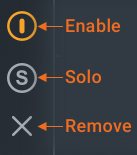
Enable
Enables or disables processing of the currently selected band.
Note
When a band is disabled, the filter will still be displayed in the EQ module panel. Disabled bands are displayed in grey to clearly differentiate them from enabled bands.
Solo
Enables temporary cutoff filters that allow frequencies within the bandwidth of the selected filter to be listened to in isolation.
Tip: Solo Band Shortcut
Hold the Alt and click on an EQ node to quickly engage the band Solo functionality.
Remove
Removes the currently selected band.
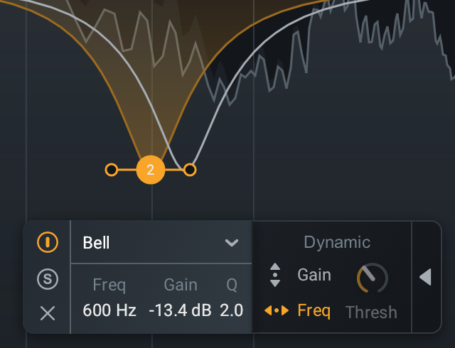
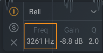
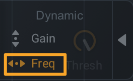
Frequency
Determines the center frequency (or cutoff frequency) (Hz) of the currently selected node. The EQ supports frequency values ranging from 20 Hz to 20 kHz.
Tips: Adjusting EQ filter Frequency
The Frequency of an EQ band can be modified using the following methods:
- Click and drag an EQ node to the left (to reduce the frequency value) or right (to increase the frequency
value).
- Hold Shift while dragging a node to the left or right to lock the movement of the node to the horizontal axis.
- Double-click on the Frequency value readout and manually enter a Frequency value in the inline edit field.
- Select a node and use the Left arrow key to decrease Frequency or use the Right arrow key to increase
Frequency.
- Hold the Shift modifier key to make coarse value adjustments.
- Hold the Command (Mac) or Ctrl (Windows) modifier key to make fine value adjustments.
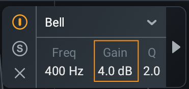
Gain
Determines the amount of gain (dB) applied by the selected filter. The EQ supports gain adjustments ranging from -30 dB to +15 dB.
Tips: Adjusting EQ filter Gain
When available for adjustment, the Gain of an EQ band can be modified using the following methods:
- Click and drag an EQ node up (to increase gain) or down (to decrease gain).
- Hold Shift while dragging a node up or down to lock the movement of the node to the vertical axis.
- Double-click on the Gain value readout and manually enter a Gain value in the inline edit field.
- Select a node and use the Up arrow key to increase Gain or use the Down arrow key to decrease Gain.
- Hold the Shift modifier key to make coarse value adjustments.
- Hold the Command (Mac) or Ctrl (Windows) modifier key to make fine value adjustments.
- Double-click on a node to reset the Gain and Q/Slope to their default values.
EQ Gain Scale
The vertical dB magnitude scale on the right edge of the EQ module panel measures the EQ filter Gain.
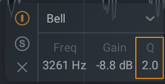
Bandwidth
Determines the width or slope (dB/octave) of the selected filter. Bandwidth is labeled as either Q or Slope in the band controls panel, depending on the selected filter shape.
Tips: Adjusting EQ filter Q/Slope
The Q/Slope of an EQ band can be adjusted using the following methods:
- Click and drag the node handles toward the node to decrease the bandwidth.
- Click and drag the node handles away from the node to increase the bandwidth.
- Double-click on the Q/Slope value readout and manually enter a Q/Slope value in the inline edit field.
- Hover the cursor over the node and use the mousewheel to adjust the Q/Slope value.
- Select a node and use Alt/Option+Left Arrow Key to decrease the bandwidth or use Alt/Option+Right
Arrow Key to increase the bandwidth.
- Hold the Shift modifier key to make coarse value adjustments.
- Hold the Command (Mac) or Ctrl (Windows) modifier key to make fine value adjustments.
- Double-click on a node to reset the Gain and Q/Slope to their default values.
Filter Types
The EQ module features 16 different filter shapes, each one belonging to one of the following filter type categories:
Pass Filter
Pass type filters are used to attenuate frequency content that is below (in the case of a high pass) or above (in the case of a low pass) a specified cutoff frequency. The degree of attenuation applied to content above or below the cutoff is determined by the slope of the filter. The EQ module includes four Pass type filter shapes in the Highpass and Lowpass sub-menus.
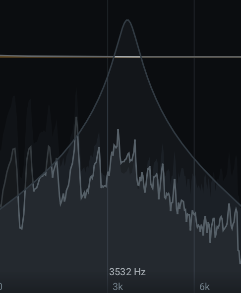
Peak Filter
Peak type filters are used to boost or cut the level of a specific center frequency. The amount of boost or cut applied to frequencies surrounding the center frequency is determined by the Q (or “Bandwidth”) of the filter. The EQ module includes four Peak type filter shapes in the Bell sub-menu.
Shelf Filter
Shelf type filters are used to boost or cut the frequency content above or below a specified frequency by the same amount. The EQ module includes Shelf type filter shapes in the Low Shelf and High Shelf sub-menus.
Filter Shape
Determines the filter shape of the currently selected band.
The filter shape dropdown menu organizes the filter shapes into the following sub-menus: Bell, Low Shelf, High Shelf, Lowpass, and Highpass.

Bell
The Bell sub-menu includes the following Peak type filters:

|
Filter Shape | Description |
|---|---|---|

|
Bell | Smoothly boosts or cuts an adjustable region around a specific frequency. Looks like a bell, come on what do you want from me. |

|
Proportional Q | Unique filter that varies shape in proportion to the amount of boost or cut applied. As a cut or boost is increased further away from center of the EQ curve, the shape tightens for more precision. |

|
Vintage | Asymmetrical bell filter that is more narrow when cutting frequencies than when boosting frequencies. |

|
Band Shelf | Bell filter with wide, flat top. Useful for boosting or attenuating a block of frequencies. |
Low Shelf
The Low Shelf sub-menu includes the following Shelf type filters:

|
Filter Shape | Description |
|---|---|---|

|
Analog | Efficient shelf filter for simple boosts and cuts. |

|
Resonant | Exhibits a complimentary resonance at both ends of the filter slope creating a complex shape with one node. |

|
Vintage | Modeled after the renowned Pultec analog equalizer. Exhibits a complimentary frequency dip, creating a complex slope with one node. |

|
Baxandall Bass | Gentle low frequency shelf. Modeled after the Baxandall EQ, with the addition of freely adjustable frequency. |
High Shelf
The High Shelf sub-menu includes the following Shelf type filters:

|
Filter Shape | Description |
|---|---|---|

|
Analog | Efficient shelf filter for simple boosts and cuts. |

|
Resonant | Exhibits a complimentary resonance at both ends of the filter slope creating a complex shape with one node. |

|
Vintage | Modeled after the renowned Pultec analog equalizer. Exhibits a complimentary frequency dip, creating a complex slope with one node. |

|
Baxandall Treble | Gentle high frequency shelf. Modeled after the Baxandall EQ, with the addition of freely adjustable frequency. |
Highpass
The Highpass sub-menu includes the following Pass type filters:

|
Filter Shape | Description |
|---|---|---|

|
Flat | Butterworth filter; optimized for maximum flatness without ripple or resonance in the passband or stopband. |

|
Resonant | Filter equipped with a resonance control to emphasize the cutoff frequency with positive gain. |
Lowpass
The Lowpass sub-menu includes the following Pass type filters:

|
Filter Shape | Description |
|---|---|---|

|
Flat | Butterworth filter; optimized for maximum flatness without ripple or resonance in the passband or stopband. |

|
Resonant | Filter equipped with a resonance control to emphasize the cutoff frequency with positive gain. |
Dynamic Processing Modes
The dynamic processing modes can be accessed by selecting a node and clicking the arrow button on the right hand side of the band controls panel.
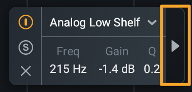
Note
If either of the dynamic processing modes are enabled for a given node, the arrow will appear orange when
the dynamic controls pop out panel is closed.
Dynamic gain or frequency processing can be enabled by clicking the Gain or Frequency buttons in the dynamic controls panel. Only one dynamic processing mode can be selected at a time for a selected band (i.e. Gain and Frequency mode cannot be enabled simultaneously for a selected band).
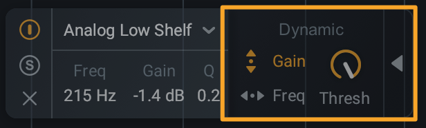
Gain Mode
Enables the ability to dynamically update the Gain of the selected EQ band when a signal exceeds the threshold level.
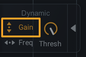
Clicking the “Gain” button in the EQ node controls panel will enable Dynamic Gain Mode for the selected node.
Note: Dynamic Gain Mode Availability
Dynamic Gain Mode is not available for Lowpass and Highpass filter shapes.
Boost or Cut Mode
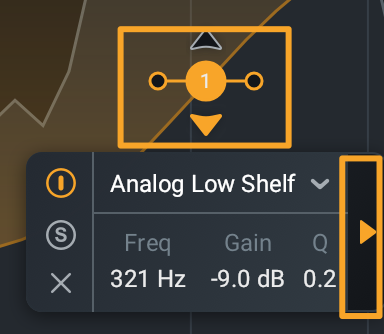
When Gain mode is enabled, small triangle icons will appear directly above and below the associated EQ node. These icons indicate the expected direction of the dynamic gain change. Clicking on either triangle icon will determine the direction of gain change.

- BOOST: Selecting the upward facing triangle will increase the gain of the filter when signals exceed
the threshold level.
- When the EQ node is placed above the zero line, the filter will be set to 0 dB of gain until it is triggered. When it is triggered by incoming signals exceeding the threshold, the gain of the filter will be increased in the direction of the node.
- When the EQ node is placed below the zero line, the gain of the filter will be increased toward the zero line when it is triggered by incoming signals exceeding the threshold.
- CUT: Selecting the downward facing triangle will decrease the gain of the filter when signals exceed
the threshold level.
- When the EQ node is placed above the zero line, the gain of the filter will be reduced toward the zero line when triggered.
- When the EQ node is placed below the zero line, the filter will be set to 0 dB of gain until it is triggered. When it is triggered by incoming signals exceeding the threshold, the gain of the filter will be reduced in the direction of the node.
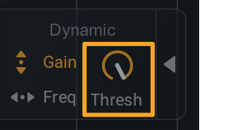
Threshold
Determines the signal level at which dynamic gain adjustments will be triggered for the selected EQ node.
Tip: Using Dynamic EQ to reduce sibilance
A dynamic EQ node can be used as an alternative to the De-esser module when attempting to reduce sibilant frequency content.
Frequency Mode
Enables the ability to dynamically update the Frequency of the selected EQ band to follow harmonics as they change.
Frequency mode works by identifying the fundamental frequency of the input signal when Frequency mode is enabled for an EQ band. It then identifies the harmonic frequency that is closest to the frequency of the selected EQ band. When the fundamental of the incoming vocal changes over time, the frequency of the EQ band will dynamically update to follow that harmonic as it changes with the fundamental. When Frequency mode is enabled and the frequency of the EQ band is manually adjusted, the EQ band will update to track the harmonic closest to the new frequency value.
Tips: When to use Dynamic Frequency Mode
- Use a Highpass filter with Dynamic Frequency Mode enabled to track the first harmonic of a vocal. This will dynamically cut out unwanted low end rumble while maintaining the character of the vocal.
- Use multiple EQ bands with Dynamic Frequency Mode enabled to change the character of a vocal by following harmonics over time without the need for automation.
- Use a Bell filter with Dynamic Frequency Mode enabled to follow and cut harsh vocal resonances.
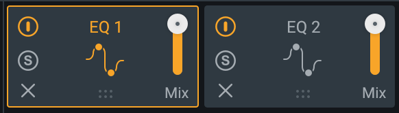
Global Module Controls
The module chain features common controls for each module, including: Bypass, Solo, Remove, Reorder, and Wet/Dry Mix.
Global Controls Chapter
To learn more about the module chain and other global controls in Nectar, visit the Global Controls chapter.
Meters
The following meters and displays are included in the EQ: Spectrum Analyzer, Composite Curve, and the Filter Response Curve.
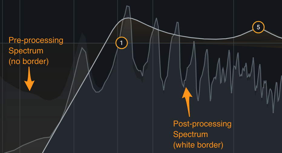
Spectrum Analyzer
Displays the magnitude (amplitude, in decibels) of the input signal across the frequency spectrum in real-time. Two spectrum analyzers are displayed in the EQ module to compare the effect of processing. The input signal to the EQ module is shown as a dark grey spectrum with no border. The processed output spectrum is drawn in the foreground with a white border.
EQ Spectrum Rulers
- The vertical ruler on the left side of the EQ module panel measures the amplitude of the spectrum.
- The vertical ruler on the right side of the EQ module panel measures the gain of the EQ nodes.
- The horizontal ruler along the bottom of the EQ module panel measures the frequency.
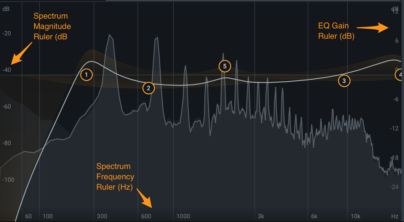
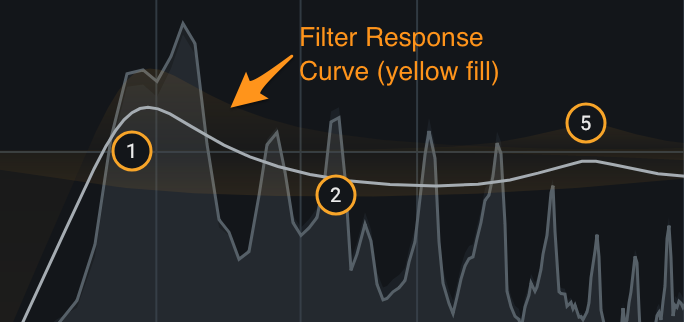
Composite Curve
The composite curve is the thick white line drawn across the EQ module panel. When EQ filters are added and modified they contribute to the overall shape of the composite curve. This curve represents the combined filter response of all enabled bands.
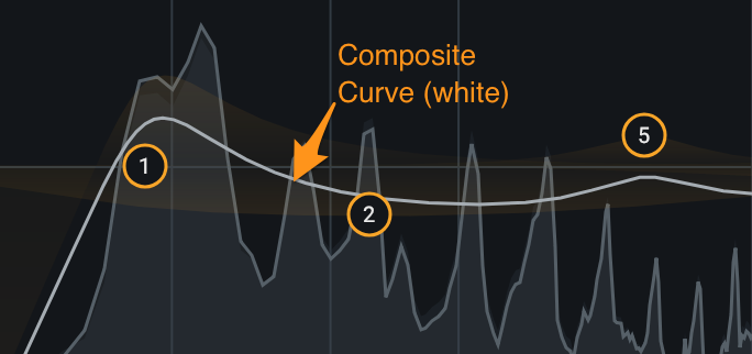
Filter Response Curve
The semi-transparent yellow fill color represents the filter response of a single band in isolation. This curve will be hidden by the white composite curve in cases where the selected filter shape is not affected by other enabled filters.