10.2 The build plate screen (3D PRINT), and adjusting your print


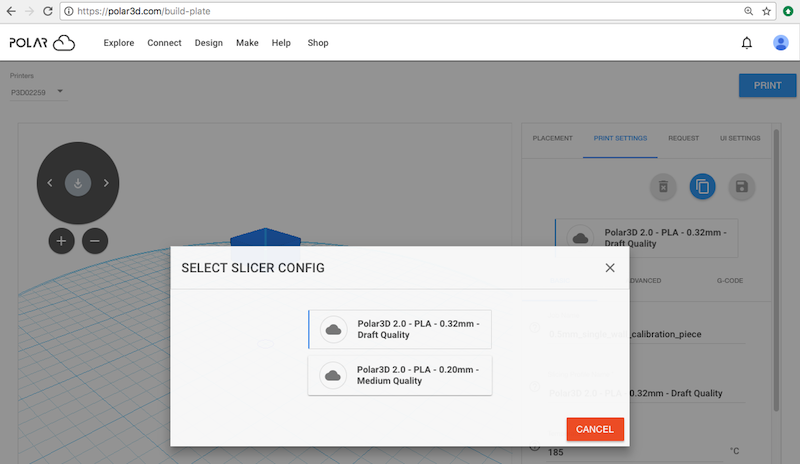
Figure 10.5: Polar Cloud build plate (3D PRINT) screen

pict

There are a number of features of interest on the build plate 3D PRINT) screen, as demonstrated in Figure 10.5; these features will be discussed in more detail below.

1.
Towards the upper left of the build plate screen is the name of the 3D printer currently selected; if multiple printers are accessible to you, you may select which one you want to print on via this drop-down menu. pict
2.
Towards the upper right is the blue “PRINT” button; press that button when your object is ready, and you wish to submit it for printing. Note that when you press “PRINT”, you will see a swirling loading icon towards the lower right of the screen as your job (with its underlying .stl files or OBJ files) is submitted to the printer, and then you will automatically go to the printer dashboard screen; see Section 10.9.
3.
The object or objects are shown positioned on the virtual build plate pane, towards the middle-left of the screen. Figure 10.5 shows an example of how the virtual build plate is represented for a Polar3D printer (or other printer with a circular build plate), with the center of the build plate indicated via a small circle. For a printer with a square build plate, the virtual build plate is represented as a square, with its center indicated via a smaller square.
4.
A dial for rotating your view of the object and build plate (with a central double-down-arrow for restoring the object to flat on the build plate), and circled “+” and “-” buttons for zooming the view in or out, are available on the left, above the view of the object itself.

pict

Note that display of this dial and the zoom in/out buttons may be disabled via the “Enable camera helper control” setting under the “UI SETTINGS” screen.

5.
When “PLACEMENT” is selected (highlighted) in the right pane (lower pane on smartphones or other narrow displays), underneath it is a list of one or more object files. Click on an object file from that list (or click on the object’s image within the virtual build plate pane) to activate the PLACEMENT” for that object.

pict

6.
When “PLACEMENT” is highlighted, five buttons appear underneath it, above the list of objects.

pict

Their functions are:

(a)
Delete selected object – delete the selected object from the build plate. (The icon will only be colored red, meaning active, if one or more objects are actually selected from the list of objects.)
(b)
Duplicate selected object – put a duplicate of the selected object on the build plate.
(c)
Load objects from external source – upload the selected object(s) (from your device or Google Drive) both to the build plate and to your private collection of objects.
(d)
Load objects from the Cloud – load additional objects from your “MY OBJECTS” Polar Cloud collection to the build plate.
(e)
Load objects from your queue – that is, add an object currently on the print queue to the build plate (that is, merge print queue jobs). (Note that this button will be grayed-out – not active – when you do not currently have any queued print jobs.)


Figure 10.6: Polar Cloud build plate MOVE of object

pict

7.
Once an object has been selected by clicking on it (either on the virtual build plate, or from the list underneath PLACEMENT”, in the rightward pane or lower pane on smartphones or other narrow displays), the “PLACEMENT” tab becomes active. Three axes of movement will appear centered within the object on the build plate, and three choices of type of movement, “MOVE”, “SCALE”, or “ROTATE”, along with three slider scales corresponding to the axes, will appear underneath “PLACEMENT” and the object list. You may move the object on the build plate, change its size, or rotate it about an axis, either by dragging and dropping the image of the object, or via the slider scales, or via numeric entry to the right of the slider scales, anytime PLACEMENT” is selected; see Section 10.2.1 for details. Figure 10.6 shows an example of the appearance of axes with “MOVE selected.
8.
Once an object has been selected by clicking on it (either on the virtual build plate, or from the list underneath PLACEMENT”, in the right-ward pane or lower pane on smartphones or other narrow displays), that object’s size will also (by default) be displayed towards the lower right of the image view, via three boxes showing, respectively, the size along the x, y, and z axes – see Figure 10.6. These three boxes are blue when the object fits on the build plate, or red when the object is off the build plate. (Note that this size display can be disabled via the “Show object dimension in mm” switch on the “UI SETTINGS screen.)

pict

9.
Optionally, (and for simplicity not shown here), a frame “bounding box” may be displayed around the object; see Section 10.2.4.
10.
Optionally, (and for simplicity not shown here), three blue boxes describing the “hotkeys” for the build plate screen (pressing a “hotkey” selects the specified PLACEMENT” mode) are displayed at the lower left of the virtual build plate pane; see Section 10.2.4.

pict

11.
When “‘PRINT SETTINGS is selected (highlighted) in the right pane (lower pane on smartphones or other narrow displays), underneath it appears a box specifying the current slicing profile; see Figure 10.7. Clicking on the slicer configuration box brings up a “SELECT SLICER CONFIG” screen at which you may select an alternate slicing profile; see Figure 10.8.

Figure 10.7: Polar Cloud build plate PRINT SETTINGS
pict


Figure 10.8: Polar Cloud build plate SELECT SLICER CONFIG pop-up screen

pict

12.
Also under “PRINT SETTINGS” are three buttons (icons) which affect the slicing profile used.

Only predefined slicing profiles

pict

Custom slicing profile(s) defined

pict

Their functions are:

(a)
Delete slicing config” – Delete the current slicing profile. (Only active when the current slicing profile is a custom profile you created; you cannot delete the Polar Cloud supplied predefined slicing profiles.)
(b)
Duplicate slicing config” – Make a duplicate (copy) of the current slicing profile, (typically so that you may then modify that duplicated slicing configuration to suit your needs).
(c)
Save config” – Save the current slicing profile (only active when the current slicing profile is a custom profile you created); your custom slicing profile will then be available as one of the slicing profiles selectable via the “SELECT SLICER CONFIG” pop-up screen (see Figure 10.8), and may be downloaded via the “Download Config File” tab on print jobs (see, for instance, Figure 10.45).

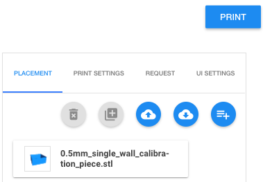
Not all of these buttons will initially be active. Clicking Duplicate slicing config” copies the current slicing profile, but with a new (draft) name. You may then “Delete slicing config” (to return to the prior slicing profile. Or if you make changes to the slicing profile – via any of the “PRINT SETTINGS” specific settings; see item 13 – then you may choose to “Save config”, saving the now-changed slicing profile under a new name.

13.
Also under “PRINT SETTINGS”, below the box naming the current slicing profile, are many additional settings, (corresponding to slicer settings) which may be used to adjust aspects of the print, such as the temperature, speed of printing, thickness of exterior walls on the object, whether to add a brim, raft, or skirt, etc.; see Figure 10.9.


Figure 10.9: Polar Cloud build plate PRINT SETTINGS: BASIC

pict

In particular, under “PRINT SETTINGS”, there are three categories and screens of settings:

(a)
The “BASIC” settings include the “Job Name”, the extruder “Temperature” (185°C is normal for the PLA filament provided by Polar 3D, but the “Temperature should always be adjusted for the type of filament you are actually using); “Filament Diameter” (which should be 1.75 mm for the PLA filament provided by Polar 3D, but especially for off-brands of filament, always measure the filament diameter precisely with calipers and set this value to match your precise filament diameter); “Support Type” for when an object requires printing with some support material at the bottom or internally; and “Platform Adhesion Type” controlling whether to add a brim, raft, or skirt when printing the object.
(b)
The “ADVANCED” settings include infill settings (density of the object’s interior), filament flow (the appropriate value depends upon the exact type of extruder in use), Retraction” settings (controlling retraction of the filament and Z hop raising of the print head during non-printing moves), “Quality” settings (adjusting the thickness of the exterior of the object), additional speed settings (e.g., for fine-tuning the speed of printing the initial layer – which may be relevant for getting good adhesion, and a good initial flow of material), and some cooling settings.
(c)
The “G-CODE” settings allow you to modify the starting and ending G-code (actual instructions to the printer).
14.
Clicking the “REQUEST” tab brings up the “REQUEST” screen for entering requests regarding filament material and color, etc., to the printer manager; see Section 10.2.3.
15.
The “UI SETTINGS” are several settings adjusting the operation of the build plate user interface, including whether or not to display the features described in items 4, 8, 9, and 10; see Section 10.2.4.
  10.2.1 The build plate screen: PLACEMENT
  10.2.2 The build plate screen: PRINT SETTINGS and the slicing profile
   10.2.2.1 The build plate screen: slicing profiles
   10.2.2.2 The build plate screen: PRINT SETTINGS BASIC
   10.2.2.3 The build plate screen: PRINT SETTINGS ADVANCED
   10.2.2.4 The build plate screen: PRINT SETTINGS G-CODE
  10.2.3 The build plate screen: print job special REQUEST
  10.2.4 The build plate screen: UI SETTINGS
  10.2.5 The build plate screen: adding or removing objects