10.2.4 The build plate screen: UI SETTINGS


Figure 10.20: Polar Cloud build plate UI SETTINGS

pict

The “UI SETTINGS” screen (see Figure 10.20) controls five options:

1.
Always show selected object’s bounding box” – This controls the presence of a wire frame “bounding box” outline around the object showing the farthest extents of the object. This may be useful in checking how close an object is getting to the edge of the build plate or to another object on the build plate. Note that even if display of an object’s bounding box is not enabled, if you “MOVE”, “SCALE”, or ROTATE” an object so that it extends beyond the edge of the build plate (indeed, if the bounding box comes within 2 millimeters of the edge of the build plate) the object’s bounding box will be displayed, in red, as a warning!


Figure 10.21: Build plate object bounding box enabled

pict

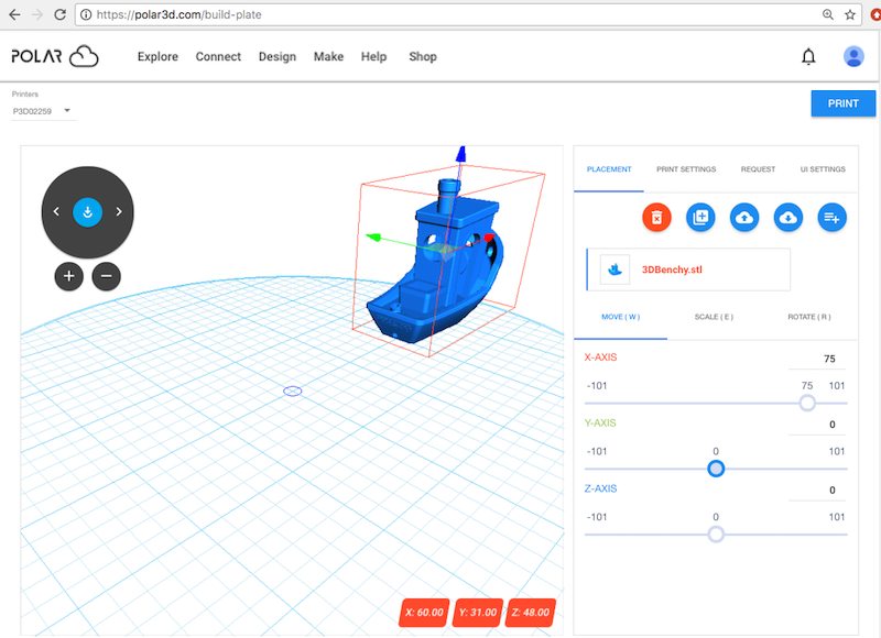
Figure 10.21 shows an example of the normal appearance of the “bounding box” outline when it has been enabled; (note that the bounding box appears around the currently selected object – and unless and until an object is actually selected, the bounding box will not be displayed). Normally displayed in blue, the bounding box will be displayed in red if the object extends (or overhangs) past the edge of the build plate; see Figure 10.22 and Figure 10.23. A red warning bounding box will be displayed when an object overhangs (or is near) the edge of the build plate even if Always show selected object’s bounding box” is not enabled!


Figure 10.22: Build plate: bounding box turns red due to overhang

pict

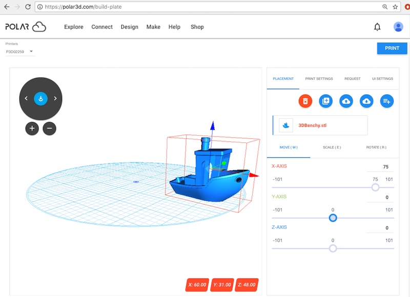
Since in some views of the object on the build plate it can be hard to tell whether the object overhangs the edge of the build plate, enabling a bounding box can provide reassurance that the object’s placement is okay. When a red bounding box is warning that the object placement is problematic, (see Figure 10.22), rotating the view of the object may allow a clearer view of the problem area, (see Figure 10.23).


Figure 10.23: Build plate: rotate and zoom to more clearly see object overhang

pict

2.
Show camera helper control” – This controls the presence (default) or absence of the rotate view dial and zoom in/out buttons at the upper left of the object-on-build-plate pane (the left pane or upper pane on narrow displays). While the rotate view dial and zoom in/out buttons are present by default, if they are distracting or “getting in the way” of your view of a portion of your object, you may disable the checkbox to make them disappear.
3.
Show hotkeys helper” – This controls whether a reminder listing the keyboard shortcuts W (move), E (scale), and R (rotate) is displayed towards the lower left of the object-on-build-plate leftward pane (upper pane on narrow displays);

pict

By default, the hotkeys reminder is not displayed, regardless of whether or not the hotkeys are actually active.

4.
Enable hotkeys” – This controls whether the keyboard shortcuts such as W (move), E (scale), and R (rotate) are active (available). Another hotkey is Q, which switches between displaying axes with respect to the object vs. displaying axes with respect to your viewing perspective.
5.
Show object dimension in mm” – This controls whether the object size (in mm) is displayed (in three small boxes, blue when the object fits on the build plate, red when the object is off the build plate – for red vs. blue boxes, compare Figure 10.21 with Figure 10.22) towards the lower right of the leftward, object-on-build-plate pane (the upper pane on narrow displays).