Gate
Table of Contents
Overview
You can use the Gate module to eliminate or attenuate unwanted signal content when the input signal falls below a given threshold level.
Module Interface

The Gate module includes the following sections:
Module Header
The controls in the module header affect the entire Gate module.

- Multiband Crossover View
- Detection Filter View
- Learn
- Reset
- LFE: (Not pictured, surround instances only.)
Multiband Crossover Spectrum View
Access the Multiband Crossover view and controls. See the Multiband Crossover View section in the General Controls chapter.
Detection Filter View
Access the Detection Filter view and controls. For more information, see the Detection Filter View below for information on each view.
Learn
Enable to allow Neutron to search for natural crossover cutoff points for multiband processing using a few criteria, including identifying minima in the frequency spectrum of the incoming audio. When it has determined and set the ideal values for the crossover cutoffs, it will turn itself off automatically. You can also manually disable learning when it is active by clicking the Learn button again.
Reset
Returns all controls in the Gate module to their factory default values. If you wish to return to settings you were using before clicking the Reset button, you can use the Undo History window to revert to the settings before the Reset event.
LFE
This option appears when Neutron is inserted on a 5.1 or 7.1 surround track. When enabled, the LFE channel will be processed along with all other channels. When disabled, the LFE channel will not be processed by the associated module. If necessary, latency compensation is applied to the LFE channel when it is disabled, to ensure timing is maintained between all channels.
Meters and Displays
The meters illustrate how the Gate is responding to and processing the input signal. The meters included are outlined in the image below.
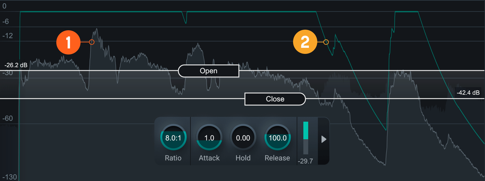
Waveform Displays
- Scrolling waveform: displays the amplitude of the input and output signals over time. The meter scrolls
from right to left, with the most recent information on the right.
- Input signal waveform: dark gray waveform displayed behind the output signal waveform.
- Output signal waveform: light gray waveform displayed in front of the input signal waveform. When the signal is gated, you can monitor the difference in the gain reduction applied to the output signal versus the input signal.
Gain Reduction Trace
Draws a line that represents the gain reduction applied to the selected band over time. Use the Gain Reduction Trace to monitor and to set the response times (attack and release) and gain reduction envelope applied over time.
Controls
Threshold Controls
You can control gating by setting the Open Threshold and Close Threshold. Click and drag the Threshold handles and place them where you want to apply gating.
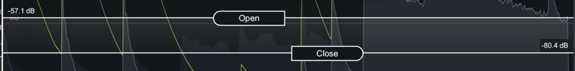
- Open Threshold: Sets the level above which the gate will open, allowing the signal to pass through. When the input signal falls ABOVE the Open threshold level, attenuation will stop.
- Close Threshold: Set below the Open threshold level at which the gate will close. This is also called hysteresis. When the input signal falls BELOW the Close threshold, it will be attenuated. Moving the Close threshold either UP or DOWN will affect your gating. By setting Close threshold lower than Open threshold, more of the decay will pass without affecting the trigger threshold.
Tip: Reduce Chatter Effect
In some situations, undesirable signals that are near thelevel of the open threshold can cause the gate to “chatter” by crossing the threshold level too often. The Close threshold helps to eliminate this chattering effect. When a signal has dropped below the Close threshold, it will not trigger the gate to open again until it exceeds the level of the Open threshold.
HUD Controls
The HUD in the Gate Module includes:
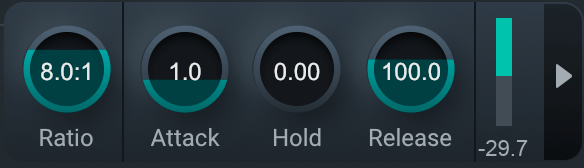
- Ratio: Determines the amount of gain reduction applied to signals that fall below the Threshold.
- Attack: Determines the amount of time (in milliseconds) it takes for the gate to transition from closed to open when a signal exceeds the Open threshold.
- Hold: Sets the amount of time (in seconds) the gate will stay fully open after a signal falls below the threshold. The hold length will vary when the release period begins.
- Release: Determines the amount of time (in milliseconds) it takes to transition from open to closed when a signal falls below the Close threshold.
- Gain Reduction Meter: Displays the current average amount of gain reduction in decibels (dB) applied to the signal.
Advanced Controls
The Sidechain controls for the currently selected band are located in the Advanced panel of the HUD. To access the Advanced Panel, click the arrow button on the right hand side of the band HUD.
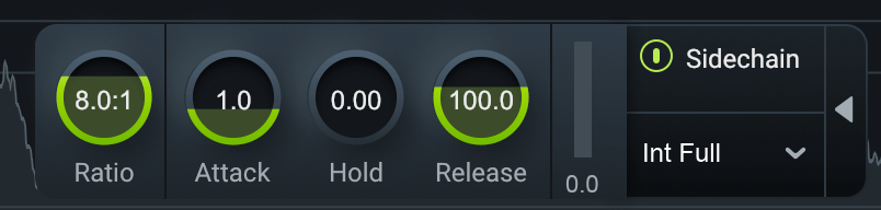
Sidechain
Allows you to trigger the amount of gain reduction in the Gate from a signal other than the input to the Gate. The signal is routed into the detection circuit of the Gate. You can choose either an internal or external input signal to trigger the Gate band’s dynamic behavior. By sidechaining, you can dynamically link elements of a mix to provide an adaptive balance between tracks.
Enabled Sidechain
When you enable Sidechain, you have the option to sidechain with an internal band or an external band. The sidechain dropdown menu will display active internal bands and active external instances categorized under internal or external as described in the list below.
- INTERNAL (INT.):
- Choose from any band currently placed in the Gate module.
- Using an internal sidechain input allows you to trigger gain reduction in the selected band from the amount of energy in a different band. For example, you can accentuate perceived low end energy by reducing high end any time the lowest band exceeds a defined threshold.
- Internal Full allows you to trigger gain reduction taking the sonic information from all active bands.
- EXTERNAL (EXT.):
- Choose from any audio from another track or bus.
- Using an external sidechain input will help balance a signal with other tracks.
- The external audio source can also be filtered through any of the bands in the Gate module by choosing any of the External bands (for example, Ext. Band 1).