Beam Layout Welding Facility In Bangalore
Most people believe that H beams and I beams are one and the same. They are not. They may share the same structure and function, but they are not the same thing. These are some differences to keep in mind.
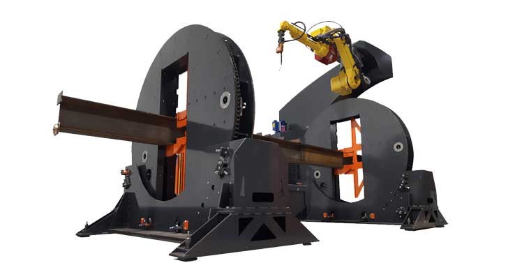
Beam Layout Welding makes it possible to join web sections together with a 100% welded seam. The edges of the two pieces are used as guides and the air cylinders clamp them in place. The grooved copper backup plate is placed against the lower end of the joint. The welding head follows the joint and welds by a single-wire, submergedarc.
It has a solid underside that holds the steel plate, while the weldheads pass through it. This is where the flanges on the H beam can be shaped and cut. The web is then created from a large piece of plate. It is then loaded onto a belt-like conveyor belt and the flanges are attached to it.
Most people believe that H beams and I beams are one and the same. They are not. They may share the same structure and function, but they are not the same thing. These are some differences to keep in mind.
The strength of a beam is often determined by its web. This is the distance between the center and the beam. Because H beams tend to be thicker and more powerful, it is easy to conclude that they are stronger. But I beams offer greater and better flange resistance than H beams.
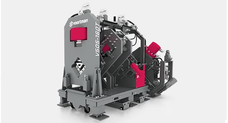
H beams are not as widely used as I beams. So H beams are not necessarily better or more cost-effective than the I beams. In case you didn't know, an H beam welding device is composed of many weldheads stacked up next to each another.
To dispense and recover welding flux, a flux recovery system can be used. Seam Welder Hydraulic Power Units and Electric Controls are used to drive conveyors at the Seam Welder's entrance and exit.
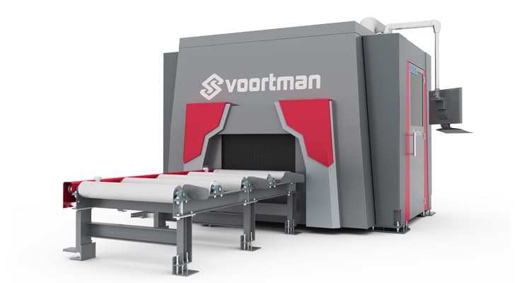
Beam Layout Welding has easily accessible diagnostics indicators and message display. Custom graphics include electrical and hydraulic diagrams, and functional and functional diagrams. You can input program information via touch screen, keyboard or touch screen.
A welded beam consists of three individual sections of steel – a web, a top flange and a bottom flange. These segments are merged together with deep fillet welds to create an incredibly robust building material.