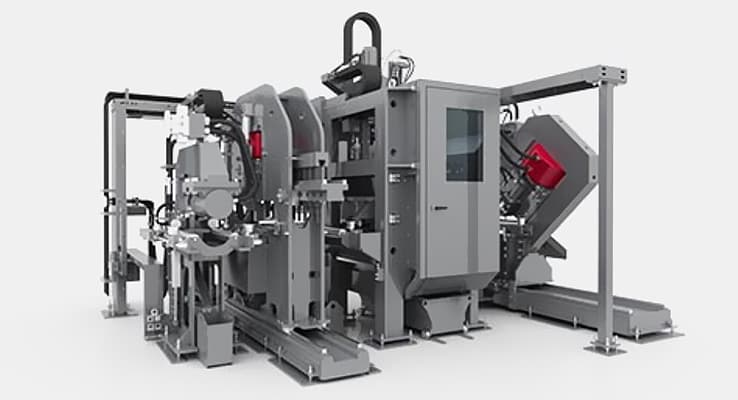
Beam Layout Welding Device

Beam Layout Welding Development


The beam's strength is determined by the web. This refers to the height or center of the beam. We can conclude that H beams are stronger because they are thicker and higher than H beams. However, I beams are stronger than H beams and have a greater flange resistance.


Beam Layout Welding consists of a trolley, a vertical column, an upper platform, tool carrier mechanism, seam tracking device and wire feeding device. Wire reel supporter, flux recovery, electrical control system, and SAW weld power.

Beam Column


With the help of our Research & Development team, we can create the exact Beam Layout welding machine that you require. If you think it is possible, let us know and we will get back to your with our findings! Our engineers are more than happy to assist you! Get a quote for the equipment or products that you are looking for by contacting us today!

Beam Column
Computer-Aided Design

Computer-Aided Design


Gulf States Saw & Machine Company can also fulfill Machine Parts orders. All you need is a simple form. You will receive a Parts Representative shortly!

Beam Layout Welding Which Of The Following


Traditional fitting requires an experienced fitter who can read and understand the assembly drawings, use the measuring tape and mark where the beam is. A laser projection system can project all information directly onto a beam, so an operator, who has limited training, can align and tack weld the connection with that line.

Beam Layout Welding Ppt

Beam Layout Welding Ppt


At Gulf States Saw & Machine Co., we understand that no two fabricators have the same need – as processes and nature of tasks may differ. We pulled together only the best of structural fabrication machines suited to your individual need. No matter what your choice range is, we’ve got you covered!

Bending


Place the two flanges on the conveyor section on opposite ends of the web. The flanges rotate into the vertical position, and are held by magnetic guides rollers. The three pieces of the web are then moved into their correct positions by means of a retractable brake and hydraulically clamped. The operator manually tackwelds the pieces together. The clamps are depressed and the tackwelded beam is transferred to the welder. After initial adjustment to the clamp positions of the first beam the operator controls material movement from the control panels for all subsequent beams with the same size.

Frequently Asked Questions

A welded beam consists of three individual sections of steel – a web, a top flange and a bottom flange. These segments are merged together with deep fillet welds to create an incredibly robust building material.