Installation position and distance
When selecting the installation location of the drive, check the following points:
The Clean Power VFD must be installed on a surface that can support the weight of the device and is free from vibration exceeding the specified tolerances.
The surface must be fire-resistant or flame-retardant and compliant with local electrical regulations.
There must be sufficient clearance around the Clean Power VFDto allow air to circulate freely.
If the Clean Power VFD is installed inside an electrical panel, ensure that the cooling fan of the Clean Power VFD is properly located within the enclosure to ensure the proper evacuation of heat from both the Clean Power VFD and the enclosure.
Minimum mounting clearance distances, single drive installation⚓
Clean Power VFD model | A mm / inch | B mm / inch | C mm / inch | D mm / inch |
|---|---|---|---|---|
SDB 1 2 185 | 300 / 11.81 | 200 / 7.87 | 50 / 1.97 | 10 / 0.39 |
Minimum mounting clearance distances, side-by-side drives installation⚓
VFD model | A mm / inch | B mm / inch | C mm / inch | D mm / inch | E mm / inch |
|---|---|---|---|---|---|
SDB 1 2 185 | 300 / 11.81 | 200 / 7.87 | 50 / 1.97 | 10 / 0.39 | 50 / 1.97 |
Tip
If a VFD is mounted above another it is important to ensure that the air temperature around the upper unit it not heated beyond the specified maximum operating temperature by the exhaust from the lower unit. An air guide between the VFD's is recommended to prevent the rising hot exhaust air from being drawing into the upper unit.
Heat dissipation⚓
VFD model | Heat dissipation at rated current output | |
|---|---|---|
W | BTU / h | |
SDB 1 2 185 | 387 | 1320.4 |
VFD model | Air flow of fans | |||
|---|---|---|---|---|
70X70X25mm Fan | 50X50X10mm Fan | |||
CFM | m3 / min | CFM | m3/min | |
SDB 1 2 185 | 13.91 | 0.39 | 12.7 | 0.36 |
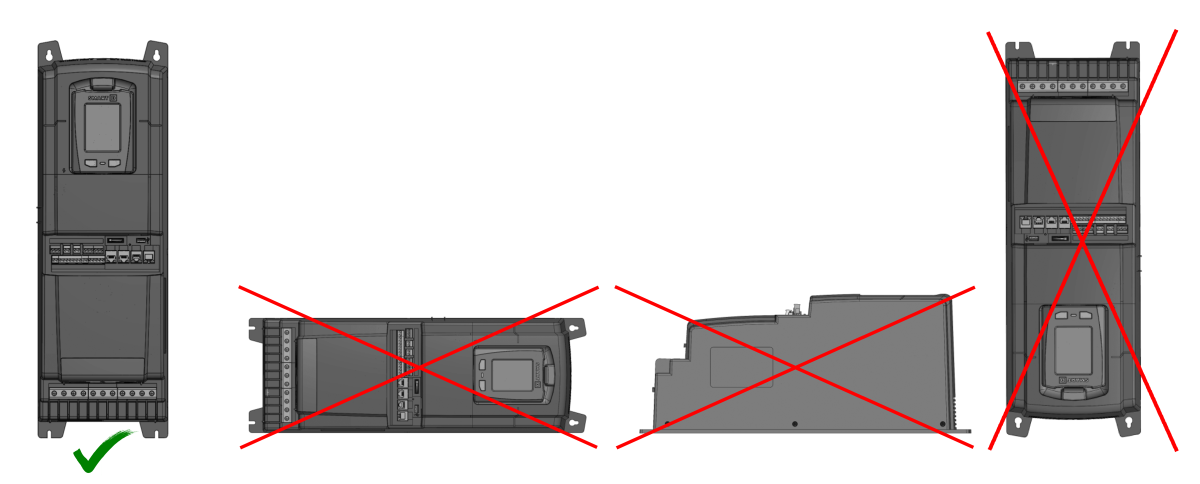
Mounting orientation⚓
For correct heat dissipation, the Clean Power VFD must be mounted vertically. But do not install it upside down.
Do not mount it on its side or on its back.