General Controls
Overview
Adjusting the General Controls will set up different parts of your mixing environment. The following will affect the entire plug-in:
The following will affect the entire module:
Resize Window
You can resize the main window by clicking and dragging the bottom right corner of the plug-in window. Neutron 3 mothership, Visual Mixer, and Neutron 3 Component Plug-ins are also resizable.
Global Controls
The Neutron 3 mothership header includes the Global Controls outlined in the image and table below. 
| Label | Control | Description |
|---|---|---|

|
Plug-in Instance Name | Determines the name of the current instance when it appears in IPC lists in supported iZotope plug-ins. |

|
Assistants | Opens the Assistants window allowing you to choose the type of assistant you wish to use. For more information, see the Assistants chapter. |

|
Preset Manager | Opens the Preset Manager window. For more information, see the Presets chapter. |

|
Undo History | The Undo History window allows you to compare previously adjusted settings in Neutron. For more information on the Undo History window, see the Undo History Controls section below. |

|
Zero Latency | Enables Zero Latency processing. When enabled, some processing options will be affected in the following ways: Disables Limiter Modes.Disables Sculptor module.Locks the crossover type in the multiband modules (Compressor 1 & 2, Transient Shaper, Exciter) to the Zero Latency one. |

|
Options | Opens up the Options window. For more information, see the Options chapter. |

|
Help | Links to the Help Documentation related to the module or button you are interacting with. |
Undo History Controls
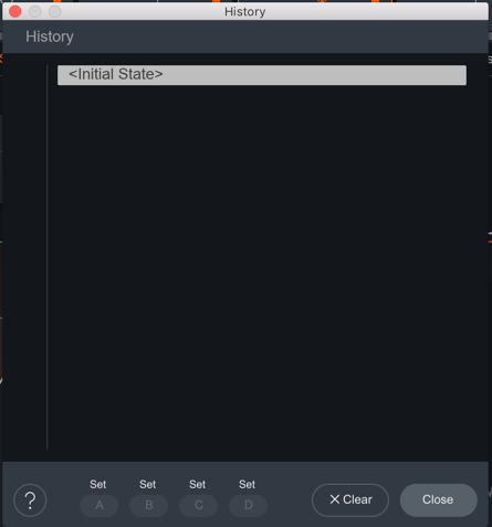
The Undo History window allows you to compare previously adjusted settings in Neutron. Clicking on Undo History will present a History list of any controls you’ve altered. You can audition the settings in the History list by clicking on one of the History list items. The table below describes the controls present in the Undo History window.
| Controls | Description |
|---|---|
| CLEAR | Click the Clear button to clear the history list at any time. |
| CLOSE | Click the Close button to close the History window. Processing resumes from the point you had last selected, so you can continue building on the History list from an earlier point. |
| SETS | You can assign up to four points in the History list to sets A, B, C, or D. This is useful for comparing a collection of different settings at once. To assign a History item to a Set:Select an item on the History list you want to capture. Click on either A, B, C, or D to assign the selected History item to the button. Click on assigned A, B, C, or D buttons to see your associated setting. |
Signal Chain
You can add, rearrange, and move the following modules in the Signal Chain:

NOTE: NUMBER OF MODULES LIMITED
Most modules can only be added to the Signal Chain once. If a module has been added to the Signal Chain already, the option in the module list will be greyed out. Only the Compressor module can be added to the Signal Chain twice.
Use the signal chain controls outlined in the table below to customize your Signal Chain.
| Icons | Controls | Description |
|---|---|---|

|
Add | Click the + button in the Signal Chain to open the module menu. Select a module from the list to add it to the last slot in the Signal Chain. |

|
Power Button | Click the power button the upper left corner of a module tile to bypass processing of that module. |

|
Module Presets | Click to access presets for the selected module. For more information, see the Preset Manager |

|
Remove | Click to remove the associated module from the Signal Chain. |

|
Reorder | Click and drag a module panel left or right within the Signal Chain to change its order in the signal flow. |

|
Wet/Dry Mix | Adjust the slider to balance between the dry (unprocessed) and wet (processed) signals. |
TIP: MODULE PRESETS AS STARTING POINT
Use the Module Preset list to help you get started on cleaning your mix. Each preset is designed to target a specific, but common issue found in a track. Play around with these presets to see how they affect your audio. Then, finely tune the parameters to your taste within the module.
NOTE: TRUE BYPASS DOES NOT AFFECT GAIN
All processing can be bypassed in True Bypass mode, except for Input Gain and Output Gain.
NOTE: PARALLEL WITH WET-DRY MIX
Use the Wet/Dry Mix slider in the signal chain to perform parallel processing.
- At 100%, you will hear only the processed audio signal.
- At 50%, you will hear a blend between unprocessed and processed audio.
NOTE: Use Mix As A Blending Tool
Mix slider allows you to adjust how much of the wet signal is added to the dry signal where dry (unprocessed) means audio input to the module, and wet (processed) means audio output from the module. The Mix affects the entire module.
I/O Panel
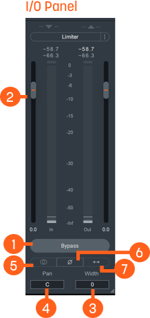
The I/O (input/output) Panel allows you to monitor levels and adjust gain, stereo width and pan, limiter settings, and channel operations.
| Label | I/O Panel Controls | Description |
|---|---|---|
|
|
Bypass | Toggle to either turn Neutron 3 instance processing on (Bypass disabled) or off (Bypass enabled). When you toggle Bypass ON (processing disabled), you will not be able to modify Neutron 3 module controls. |
|
|
Gain (Input/Output) | Adjusts the input or output gain. Output gain level comes before the Limiter in the signal flow. |
|
|
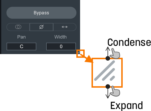
Width | Adjusts the amount of stereo widening. Decreasing this control results in a narrowing effect (-100% is equivalent to mono), increasing this control widens the apparent stereo field. Only functional in stereo instances of Neutron. |
|
|
Pan | Pans the output signal to the left or right channel. Only functional in stereo instances of Neutron. |
|
|
Sum To Mono | Toggle on to sums the left and right channels from the stereo signal into a mono output signal. Use to help you check your audio’s mono compatibility. |
|
|
Invert Phase | Enable to invert the polarity of the signal. |
|
|
Swap Channels | Enable to route the left channel to the right channel output and the right channel to the left channel output. |

|
Limiter | Enable to apply transparent limiting while preserving transients in the output. See Limiter section below for more information. |
Limiter
Enable to allow the BS.1770-2/3-compliant1 True Peak Limiter to process digital loudness maximization of your output signal while preventing True Peak overflows across all of your mono, stereo, and surround channels.
You can use the following Limiter controls to customize the Limiter’s capabilities:
NOTE: Gain Reduction Imposed By Limiter is Orange
When the Limiter is actively limiting audio, you will see the amount of gain reduction shown in orange from the top of the meter.
NOTE: Output Gain Slider and Limiter
Acts as Limiter input gain when the Limiter is enabled. Slide up or down to increase the loudness of your audio up to 10dB of additional input gain to the Limiter without affecting the True Peak level.
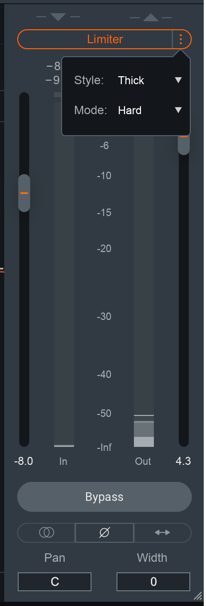
Ceiling
Determines the maximum output level of your audio. All peaks above this point will be limited. You can set the Ceiling of the Limiter via the Ceiling slider overlaid on the output meter, within a range of 0 to -20 dB.
There are two ways you can adjust the Ceiling slider:
- Click and drag the Ceiling slider UP or DOWN to the desired value.
- Hover over the Ceiling readout, and click and drag the mouse UP or DOWN to the desired value.
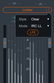
Limiter Style
You can choose from one of three user-definable character options for more direct control over the adaptive, transparent nature of the limiting algorithm.
| Character | Description |
|---|---|
| Clear | The Limiter will respond more quickly in order to better present fast-moving transient material in the mix. |
| Smooth | Smooth is the most common, best-sounding middle ground between Clear and Thick. It’s the most appropriate algorithm for the majority of program material, including most vocals and dialogue. |
| Thick | The Limiter will respond to audio more slowly, useful for louder, slower-moving sounds like a big explosion sound effect, or a bass/low-frequency swell, where you wouldn’t want an aggressive limiter to break the sound up. |
Limiter Mode
You can choose to optimize the Limiter in three different ways using the algorithms described in the table below. Each algorithm has a different sonic quality and latency requirement.
| Limiting Algorithm | Sonic Quality | Latency Requirement |
|---|---|---|
| IRC II | Transparency | Higher latency: 3772 samples at 48 kHz Ensures maximum transparency when hitting the limiter hard, particularly with low frequencies that you’d like to remain loud, without crunch or distortion. |
| IRC LL | Low Latency | Lower Latency: minimum is 120 samples at 48 kHz ensure efficient performance, yet still maintains a high level of sound quality and broadcast-standard True Peak performance. |
| Hard | Brickwall | Zero Latency Most latency-efficient algorithm. Final output level does not exceed the ceiling. Not True Peak compliant due to zero latency. |
NOTE: Low Latency is Important to Consider
Low latency is important to avoid lag or loss of sync when mixing to picture, dealing with limited latency compensation, or a control surface that needs to remain responsive.
Limiter LFE
When in surround-sound configurations, the Limiter is linked across all channels. This means that gain
reduction is applied equally to preserve the positioning of the surround image and avoid steering.
When enabled, the LFE Bypass will ensure that any audio information in the LFE channel is passed through
unprocessed, but with the correct latency compensation. For more information, see the
LFE section below.
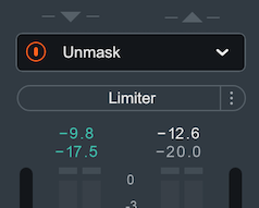
Unmask Controls
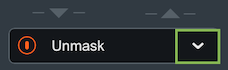
When Neutron is selected in the Unmask source menu in Nectar and masking is detected by Vocal Assistant, an EQ cut curve will be applied to the output of Neutron to unmask the vocal track. An Unmask control box will appear above the I/O meters in the Neutron interface that is unmasking the vocal track.
Depending on the edition of Nectar you are using, different Unmask controls will be available in Neutron:
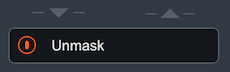
- Using Nectar
Standard edition: An Unmask EQ power button will appear in
the Neutron instance that is unmasking the vocal.
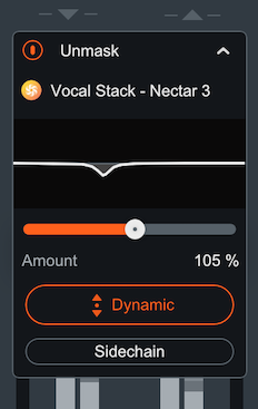
- Using Nectar
Plus edition: The Unmask box in Neutron will include a
power button and an expandable advanced controls panel. The Advanced unmask controls panel includes: the
Nectar
Plus instance name that Neutron is unmasking, an Unmask EQ curve
display, EQ amount control, Dynamic Unmask EQ on/off, and an external sidechain option when Dynamic mode is
enabled.
I/O Panel Meters
The Input and Output meters display Peak and RMS metering information.
- The current Peak value is displayed in white.
- The current RMS value is displayed in light grey.
The text readouts directly above the meters display the current Peak and RMS values.
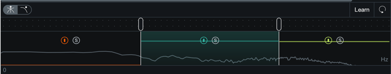
Multiband Crossover Spectrum View
You can use the Multiband Crossover Spectrum View to select, adjust, and audition processing bands in mulitband modules. The following modules include multiband processing: Compressor, Exciter, Gate, and Transient Shaper. Each multiband module supports up to three adjustable processing bands.
| Icons | Control | Description |
|---|---|---|
|
|
ADD | To add Crossover Cutoff nodes, hover over the Crossover Cutoff node bar and click on the + button that appears. You can add up to 3 crossover regions. |
|
|
REMOVE | To remove Crossover Cutoff nodes, hover over the band area and click the x button. |
|
|
POWER BUTTON | Toggle ON/OFF to enable/disable processing for the cutoff section. |

|
SOLO | Enable to hear only the band selected. |
Gain Reduction Trace
Displays the amount of gain reduction being applied to the band.
Adjusting Crossover Cutoffs
You can manually adjust the multiband crossover points in the crossover mini- spectrum view using the following methods:
- CLICK & DRAG CUTOFF HANDLES
- Hovering over the crossover handle.
- Left-click and drag the handle left or right to the desired position.
- Use the frequency readout at the bottom of the handle while dragging as a reference to where the crossover point is in relation to frequency.
- ENTER TEXT INPUT
- Double-click on a crossover handle to open the readout as a text edit field.
- Type the desired frequency value for the crossover cutoff into this field.
- Hit the enter or return key to update the value.
NOTE: Crossover cutoff points are not shared
Crossover cutoff points are not shared across multiband modules. Adjusting a crossover point in one module will not affect the crossover points in other multiband modules.
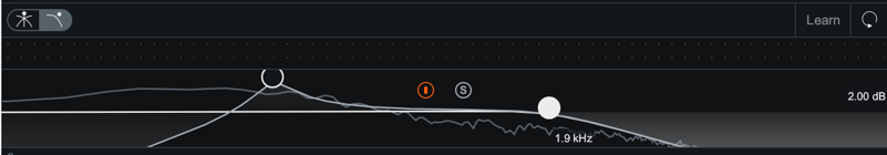
Detection Filter View
Enable the Detection Filter to adjust the frequency response of the detection circuit. When the Detection Filter is active, you can access the controls outlined in the table and image below. Neutron 3 includes detection filter processing in only the Compressor module and Gate module.
| Icons | Control | Description |
|---|---|---|
|
|
Power Button | Toggle ON to enable the Sidechain Filter. By default the Detection Filter is OFF. |
|
|
Solo | Enable to audition the output of the Detection Filter. This can be useful to enable when adjusting the Detection Filter nodes. |

|
Resonant Filter Nodes | Adjusts gain and center frequency in lowpass bands and highpass bands. |
Resonant Filter Node Adjustments
The Resonant Filter Nodes are displayed within the the Detection Filter view. You can use these to tailor your frequency response:
- Click and drag the resonant filter nodes UP or DOWN to increase or decrease gain.
- Click and drag the resonant filter nodes LEFT or RIGHT to adjust the center frequency.
TIP: Compressor Detection Filter
- Making adjustments in the Detection Filter allows you to tailor the Compressor’s sensitivity to different frequencies. This is useful when using the Compressor in single band mode.
- For example: If you want the Compressor to react more to sibilant or harsh frequencies rather than low-frequency content, you can filter out low frequencies using the high-pass filter and boost sibilant frequencies using the resonant low-pass filter to adjust the signal that the Compressor treats as the input signal.
LFE (Low-frequency effects)
The LFE (Low-Frequency Effects) button only appears when Neutron 3 Advanced is loaded on 5.1 or 7.1 surround
tracks. LFE For more information on surround sound support, see the Surround Sound section
below.
You can find the LFE button for modules in the module header.

- Enable to include LFE in the audio processing. This is the default setting.
- Disable the LFE button to exclude low frequencies when passing audio through the Low Frequency Effects (LFE) channel with the relative latency compensation.
LFE Rolloff Filter
If you happen to be mixing to a surround-sound spec that requires a band-limited LFE signal, the 24 dB/octave LFE roll-off filter helps you achieve this. Access this filter in the Options Menu under the Metering Tab, where you’ll be able to enable the filter and select the cutoff value.
NOTE: LFE Rolloff Filter
This option only appears when Neutron is instantiated on a 5.1 or 7.1 surround track.
Surround Sound
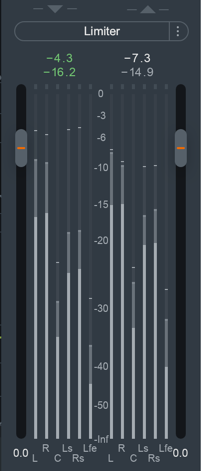
Neutron 3 Advanced supports the following surround sound formats in the following hosts. Neutron processes all channels equally unless LFE processing is bypassed in any particular module.
| DAW | Surround Format | Channel Configurations |
|---|---|---|
| Pro Tools | Film | 1.0, 2.0, 3.0 (LCR), 4.0 (Quad), 5.0, 5.1, 7.0, 7.1 |
| Logic Pro | DTS, ITU/SMPTE, SDDS | 1.0, 2.0, 4.0 (Quad), 4.0 (LCRS), 5.1 (ITU/SMPTE) |
| Cubase | ITU/SMPTE | 1.0, 2.0, 3.0 (LRC), 3.0 (LRS), 4.0 (Quad), 4.0 (LCRS), 5.0, 5.1 |
| Nuendo | DTS, ITU/SMPTE, SDDS | 1.0, 2.0, 4.0 (Quad), 4.0 (LRCS), 5.0, 5.1, 7.0 (cine), 7.0 (music), 7.1 (cine), 7.1 (music) |
Surround Sound configuration in Neutron 3 will include LFE button and surround sound meters in the I/O panel as seen in the image below.