Neutron 3 Help Documentation
Introduction

Neutron 3 is designed to bring your mix workflows into the 21st century. Now with Mix Assistant, Neutron 3 is the first-ever plug-in that listens to your entire session to suggest an overall level mix to kick things off right. With eight modular mixing tools in one mothership plug-in, it’s the easiest, most intelligent way to bring unrivaled quality and speed to your mix.
Create custom presets for individual tracks with Track Assistant, communicate across plug-ins in your session with the smartest EQs on the planet, bend and shape your audio to any instrument profile with Sculptor, and automatically find and fix masking issues with the most intelligent Masking Meter for a mix that sounds better than ever, faster than ever.
Neutron 3 packages the latest advances in audio and passes them on to you—so you can focus on your craft.
| PLUG-IN | STANDARD | ADVANCED | NEW |
|---|---|---|---|
| Neutron 3 | X | X | |
| Neutron 3 EQ | X | ||
| Neutron 3 Compressor | X | ||
| Neutron 3 Exciter | X | ||
| Neutron 3 Transient Shaper | X | ||
| Neutron 3 Gate | X | ||
| Neutron 3 Sculptor | X | NEW! | |
| Relay | X | X | NEW! |
| Tonal Balance Control | X | ||
| Visual Mixer | X | X |
Getting Started
Overview
Welcome to Neutron 3! If you have never used an iZotope product or want to know more about Neutron, then this is the right chapter for you. The topics include:
- Authorizing Neutron
- Navigating the Neutron 3 Interface
- Signal Flow
- Working with Neutron Plug-ins
- Workflow Suggestions
- Working with IPC
- Optimizing Performance
Authorizing Neutron
The first time you open a Neutron 3 plug-in, the Authorization window will appear.

The Authorization window allows you to:
- TRIAL: Start or continue a Trial period evaluation prior to purchasing.
- DEMO: Continue evaluating the product with Demo limitations (after the 10 day Trial period ends).
- AUTHORIZE: Authorize the product with a serial number.
Trial Mode
Trial mode allows you to evaluate Neutron 3 over a 10 day trial period. The trial period begins when you first open Neutron 3 plug-ins in a DAW/NLE. The Authorization window will display the number of days remaining in your trial period. Click the Continue button to exit the Authorization window.
Demo Mode
After your 10 day trial period expires, you have the option to operate Neutron 3 in Demo mode. To continue evaluating Neutron 3 in demo mode, click the Demo button.
Demo Mode Limitations
- Neutron 3 plug-ins will periodically output silence when operating in demo mode.
- Mix Assistant’s Balance feature will only be available during the Trial period of Neutron 3 and will be disabled once in Demo mode.
Authorization Methods
To disable Trial or Demo mode, you must authorize the product with a valid serial number. We offer three authorization methods for Neutron 3:
- Online Authorization: Authorize Neutron 3 on a computer online.
- Offline Authorization: Authorize Neutron 3 on a computer offline.
- iLok Authorization: Authorize Neutron 3 using iLok.
INFO: More Authorization Help
- For information about Authorization, please visit the iZotope website: https://www.izotope.com/authorization
- For additional help authorizing Neutron 3, visit iZotope Customer Care information on the iZotope website: http://www.izotope.com/support or contact our Customer Care department by sending an email to: mailto:support@izotope.com.
- More information about iZotope’s Customer Care department and policies can be found in the iZotope Customer Care chapter.
Navigating the Neutron 3 Interface
The Neutron 3 plug-in interface is divided into four main areas as seen in the image below and described in the table below.

| Label | Control | Description |
|---|---|---|

|
Global Header | The global header area provides access to: the IPC plug-in name editor, Track and Mix Assistant features, the Preset Manager, Undo History, Zero Latency, Options, and Help. |

|
Signal Chain | The Signal Chain allows you to add or remove modules and adjust the processing order of modules included in the chain. The Signal Chain area is exclusive to the Neutron 3 mothership plug-in, Neutron 3 component plug-ins do not include the Signal Chain because they only include one processing module. See the Signal Chain section for more information. |

|
I/O Panel | The I/O (Input/Output) panel area includes: global (I/O) gain controls, I/O metering, channel operations controls, and global bypass. See the I/O Panel section for more information. |

|
Module Interface | The module panel area includes all controls and meters associated with a specific processing module. |
Learn more about the I/O panel and Global header
Learn more about the controls in the Global Header and I/O Panel in the General Controls chapter.
Signal Flow
The following diagram represents the overall signal flow of the Neutron 3 plug-ins.
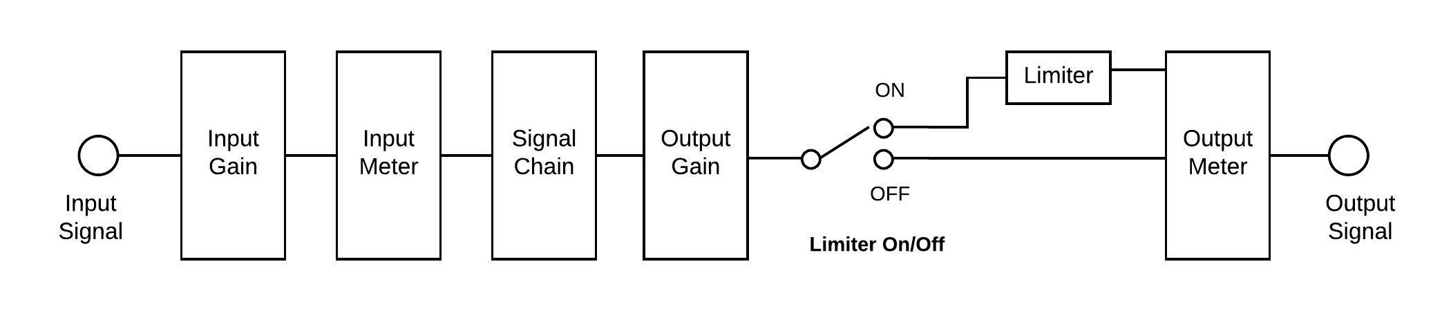
- Input Gain
- Signal Chain (Mothership plug-in only)
- Output Gain
- Limiter (Mothership plug-in only)
Working with the Signal Chain
You can add, remove, and reorder modules in the Signal Chain area of the Neutron 3 mothership plug-in. By default, the Neutron 3 Signal Chain includes the Equalizer module.
Learn more about the Signal Chain
For more information about working with the Signal Chain, visit the General Controls chapter.
Working with Neutron Plug-ins
Throughout this manual, the terms “Mothership” and “Component” are used to describe plug-ins included with Neutron 3 Standard or Advanced.
Mothership plug-in
- Refers to the main Neutron 3 plug-in.
- Offers multiple processing modules in a single plug-in instance.
Component plug-in
- Refers to the plug-in equivalent of any individual module included in the Neutron Mothership plug-in. i.e. Compressor, Equalizer, etc…
- Offers focused control over an individual processing module.
- When working with a single processing module, component plug-ins can be used as resource-friendly alternatives to the mothership plug-in.
Mothership & component plug-in feature differences
Some features included in the Neutron 3 mothership plug-in are not available in the Neutron 3 component plug-ins. Differences include:
Component Plug-in and Module Comparison
The following table outlines if a given Neutron component plug-in is also included as a module within the Neutron mothership plug-in.
| Feature | Component Plug-in | Module |
|---|---|---|
| Compressor | ✓ | ✓ |
| Equalizer | ✓ | ✓ |
| Exciter | ✓ | ✓ |
| Gate | ✓ | ✓ |
| Sculptor | ✓ | ✓ |
| Transient Shaper | ✓ | ✓ |
| Tonal Balance Control 2 | ✓ | X |
| Visual Mixer | ✓ | X |
| Relay | ✓ | X |
Workflow suggestions
There are a number of different ways to approach working with Neutron plug-ins. We’ve included some workflow suggestions you can use if you aren’t sure where to start. These workflows are merely suggestions and any workflow is valid if it works for you.
Using Presets
Neutron 3 plug-ins include a built in preset manager with a wide variety of factory presets to get you started. Open the Preset Manager by clicking the Presets button in the global header area of any Neutron 3 plug-in (except for Visual Mixer). Load a preset by selecting it in the preset manager window or quickly try out different global presets by clicking the left and right arrow buttons directly to the right of the Presets button in the global header area.
Learn more about the Preset Manager
Learn more about working with the Neutron Preset Manager in the Presets chapter.
Module Presets in the Neutron Mothership Plug-in
The Neutron mothership plug-in includes a global preset manager and a module preset manager. You can load presets that apply to a single module by clicking the Preset button in the module’s Signal Chain selector.
Using the Assistant Features
The Neutron 3 mothership plug-in and Neutron 3 Visual Mixer plug-in offer intelligent assistive features aimed at helping you find a starting point for your track or entire mix based on an analysis of your audio.
Track Assistant
Use Track Assistant to build a starting point for an individual track. You can access the Track Assistant feature by inserting the Neutron 3 mothership plug-in on a track and clicking the Assistant button to the left of the Presets button in the global header area.
Learn more about Track Assistant
See the Track Assistant section of the Assistants chapter for more information about working with Track Assistant.
Mix Assistant
Use Mix Assistant to balance levels and create a starting point for your mixing session. You can access the Mix Assistant feature from the Neutron 3 mothership plug-in and the Neutron 3 Visual Mixer plug-in. Insert the mothership plug-in on a track with audio on it or insert the Neutron 3 Visual Mixer plug-in on any track in your session and click the Assistant button to open the Assistant setup.
Learn more about Mix Assistant
See the Mix Assistant section of the Assistants chapter for more information about setting up Mix Assistant.
Working with IPC
Wouldn’t it be cool if all of the iZotope products that you owned talked to each other? Well, it’s a dream come true! With iZotope’s Inter Plug-in Communication (IPC) technology, different iZotope plug-in instances on separate tracks can send data back and forth to each other.
Neutron 3 includes the following IPC functionality:
- The Masking Meter feature, included in the Equalizer module and component plug-in, uses IPC technology to highlight masking occurring between tracks with IPC compatible plug-ins. See the Masking Meter chapter for more information.
- The Mix Assistant feature, included in the Neutron 3 mothership and Visual Mixer plug-ins, uses IPC technology to provide a starting point for your mix by grouping and adjusting levels of IPC compatible plug-ins in your session. See the Mix Assistant chapter for more information.
- Visual Mixer uses IPC technology to adjust level, pan, and width controls of compatible IPC plug-ins across your session. For more information, see the Visual Mixer chapter.
Optimizing Performance
We put a great deal of effort into improving the performance of Neutron plug-ins for the Neutron 3 release. Some notable areas of improvement include:
- Improved memory usage: We improved memory performance of Neutron 3 plug-ins, allowing you to use more plug-ins before you have to worry about running low on RAM
- Start-up time optimizations: We took a look at what we were doing when a plug-in was instantiated and made some improvements to make our plug-ins load faster. As a result, you may see small pauses when first adding modules or using certain features in a given instance.
- DSP Optimizations: We have improved the overhead of processing each buffer. This means lower buffer sizes should be faster to process. Larger buffer sizes do not benefit as much from this.
There are many factors that contribute to performance. It can be very hard to nail down exactly what is causing performance issues. Some factors include:
- Computer specifications (CPU, RAM, etc…)
- DAW and session configuration (number of tracks or plug-ins, buffer size, sample rate, etc…)
- Individual plug-in settings
If you do start to reach the limits of your particular machine, here are some things you can do to improve performance:
- Remove any modules that are not in use from the signal chain.
- Neutron Advanced users: If you are only using one module in the mothership plug-in, consider using a component plug-in instead.
- If possible, adjust the buffer size setting in your DAW.
General Controls
Overview
Adjusting the General Controls will set up different parts of your mixing environment. The following will affect the entire plug-in:
The following will affect the entire module:
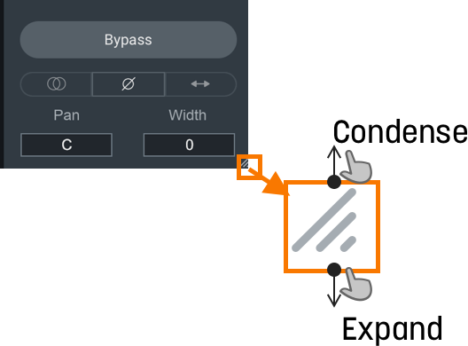
Resize Window
You can resize the main window by clicking and dragging the bottom right corner of the plug-in window. Neutron 3 mothership, Visual Mixer, and Neutron 3 Component Plug-ins are also resizable.
Global Controls
The Neutron 3 mothership header includes the Global Controls outlined in the image and table below. 
| Label | Control | Description |
|---|---|---|
|
|
Plug-in Instance Name | Determines the name of the current instance when it appears in IPC lists in supported iZotope plug-ins. |
|
|
Assistants | Opens the Assistants window allowing you to choose the type of assistant you wish to use. For more information, see the Assistants chapter. |
|
|
Preset Manager | Opens the Preset Manager window. For more information, see the Presets chapter. |
|
|
Undo History | The Undo History window allows you to compare previously adjusted settings in Neutron. For more information on the Undo History window, see the Undo History Controls section below. |

|
Zero Latency | Enables Zero Latency processing. When enabled, some processing options will be affected in the following ways: Disables Limiter Modes.Disables Sculptor module.Locks the crossover type in the multiband modules (Compressor 1 & 2, Transient Shaper, Exciter) to the Zero Latency one. |

|
Options | Opens up the Options window. For more information, see the Options chapter. |

|
Help | Links to the Help Documentation related to the module or button you are interacting with. |
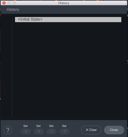
Undo History Controls
The Undo History window allows you to compare previously adjusted settings in Neutron. Clicking on Undo History will present a History list of any controls you’ve altered. You can audition the settings in the History list by clicking on one of the History list items. The table below describes the controls present in the Undo History window.
| Controls | Description |
|---|---|
| CLEAR | Click the Clear button to clear the history list at any time. |
| CLOSE | Click the Close button to close the History window. Processing resumes from the point you had last selected, so you can continue building on the History list from an earlier point. |
| SETS | You can assign up to four points in the History list to sets A, B, C, or D. This is useful for comparing a collection of different settings at once. To assign a History item to a Set:Select an item on the History list you want to capture. Click on either A, B, C, or D to assign the selected History item to the button. Click on assigned A, B, C, or D buttons to see your associated setting. |
Signal Chain
You can add, rearrange, and move the following modules in the Signal Chain:

NOTE: NUMBER OF MODULES LIMITED
Most modules can only be added to the Signal Chain once. If a module has been added to the Signal Chain already, the option in the module list will be greyed out. Only the Compressor module can be added to the Signal Chain twice.
Use the signal chain controls outlined in the table below to customize your Signal Chain.
| Icons | Controls | Description |
|---|---|---|

|
Add | Click the + button in the Signal Chain to open the module menu. Select a module from the list to add it to the last slot in the Signal Chain. |

|
Power Button | Click the power button the upper left corner of a module tile to bypass processing of that module. |

|
Module Presets | Click to access presets for the selected module. For more information, see the Preset Manager |

|
Remove | Click to remove the associated module from the Signal Chain. |

|
Reorder | Click and drag a module panel left or right within the Signal Chain to change its order in the signal flow. |

|
Wet/Dry Mix | Adjust the slider to balance between the dry (unprocessed) and wet (processed) signals. |
TIP: MODULE PRESETS AS STARTING POINT
Use the Module Preset list to help you get started on cleaning your mix. Each preset is designed to target a specific, but common issue found in a track. Play around with these presets to see how they affect your audio. Then, finely tune the parameters to your taste within the module.
NOTE: TRUE BYPASS DOES NOT AFFECT GAIN
All processing can be bypassed in True Bypass mode, except for Input Gain and Output Gain.
NOTE: PARALLEL WITH WET-DRY MIX
Use the Wet/Dry Mix slider in the signal chain to perform parallel processing.
- At 100%, you will hear only the processed audio signal.
- At 50%, you will hear a blend between unprocessed and processed audio.
NOTE: Use Mix As A Blending Tool
Mix slider allows you to adjust how much of the wet signal is added to the dry signal where dry (unprocessed) means audio input to the module, and wet (processed) means audio output from the module. The Mix affects the entire module.
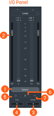
I/O Panel
The I/O (input/output) Panel allows you to monitor levels and adjust gain, stereo width and pan, limiter settings, and channel operations.
| Label | I/O Panel Controls | Description |
|---|---|---|
|
|
Bypass | Toggle to either turn Neutron 3 instance processing on (Bypass disabled) or off (Bypass enabled). When you toggle Bypass ON (processing disabled), you will not be able to modify Neutron 3 module controls. |
|
|
Gain (Input/Output) | Adjusts the input or output gain. Output gain level comes before the Limiter in the signal flow. |
|
|
Width | Adjusts the amount of stereo widening. Decreasing this control results in a narrowing effect (-100% is equivalent to mono), increasing this control widens the apparent stereo field. Only functional in stereo instances of Neutron. |
|
|
Pan | Pans the output signal to the left or right channel. Only functional in stereo instances of Neutron. |
|
|
Sum To Mono | Toggle on to sums the left and right channels from the stereo signal into a mono output signal. Use to help you check your audio’s mono compatibility. |
|
|
Invert Phase | Enable to invert the polarity of the signal. |
|
|
Swap Channels | Enable to route the left channel to the right channel output and the right channel to the left channel output. |

|
Limiter | Enable to apply transparent limiting while preserving transients in the output. See Limiter section below for more information. |
Limiter
Enable to allow the BS.1770-2/3-compliant1 True Peak Limiter to process digital loudness maximization of your output signal while preventing True Peak overflows across all of your mono, stereo, and surround channels.
You can use the following Limiter controls to customize the Limiter’s capabilities:
NOTE: Gain Reduction Imposed By Limiter is Orange
When the Limiter is actively limiting audio, you will see the amount of gain reduction shown in orange from the top of the meter.
NOTE: Output Gain Slider and Limiter
Acts as Limiter input gain when the Limiter is enabled. Slide up or down to increase the loudness of your audio up to 10dB of additional input gain to the Limiter without affecting the True Peak level.
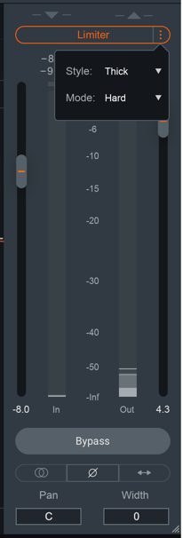
Ceiling
Determines the maximum output level of your audio. All peaks above this point will be limited. You can set the Ceiling of the Limiter via the Ceiling slider overlaid on the output meter, within a range of 0 to -20 dB.
There are two ways you can adjust the Ceiling slider:
- Click and drag the Ceiling slider UP or DOWN to the desired value.
- Hover over the Ceiling readout, and click and drag the mouse UP or DOWN to the desired value.
Limiter Style
You can choose from one of three user-definable character options for more direct control over the adaptive, transparent nature of the limiting algorithm.
| Character | Description |
|---|---|
| Clear | The Limiter will respond more quickly in order to better present fast-moving transient material in the mix. |
| Smooth | Smooth is the most common, best-sounding middle ground between Clear and Thick. It’s the most appropriate algorithm for the majority of program material, including most vocals and dialogue. |
| Thick | The Limiter will respond to audio more slowly, useful for louder, slower-moving sounds like a big explosion sound effect, or a bass/low-frequency swell, where you wouldn’t want an aggressive limiter to break the sound up. |
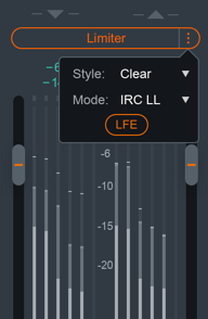
Limiter Mode
You can choose to optimize the Limiter in three different ways using the algorithms described in the table below. Each algorithm has a different sonic quality and latency requirement.
| Limiting Algorithm | Sonic Quality | Latency Requirement |
|---|---|---|
| IRC II | Transparency | Higher latency: 3772 samples at 48 kHz Ensures maximum transparency when hitting the limiter hard, particularly with low frequencies that you’d like to remain loud, without crunch or distortion. |
| IRC LL | Low Latency | Lower Latency: minimum is 120 samples at 48 kHz ensure efficient performance, yet still maintains a high level of sound quality and broadcast-standard True Peak performance. |
| Hard | Brickwall | Zero Latency Most latency-efficient algorithm. Final output level does not exceed the ceiling. Not True Peak compliant due to zero latency. |
NOTE: Low Latency is Important to Consider
Low latency is important to avoid lag or loss of sync when mixing to picture, dealing with limited latency compensation, or a control surface that needs to remain responsive.
Limiter LFE
When in surround-sound configurations, the Limiter is linked across all channels. This means that gain
reduction is applied equally to preserve the positioning of the surround image and avoid steering.
When enabled, the LFE Bypass will ensure that any audio information in the LFE channel is passed through
unprocessed, but with the correct latency compensation. For more information, see the
LFE section below.
Unmask Controls
When Neutron is selected in the Unmask source menu in Nectar and masking is detected by Vocal Assistant, an EQ cut curve will be applied to the output of Neutron to unmask the vocal track. An Unmask control box will appear above the I/O meters in the Neutron interface that is unmasking the vocal track.
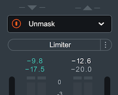
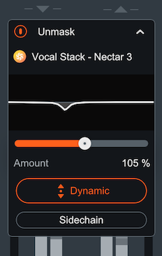
Depending on the edition of Nectar you are using, different Unmask controls will be available in Neutron:
- Using Nectar
Standard edition: An Unmask EQ power button will appear in
the Neutron instance that is unmasking the vocal.

- Using Nectar
Plus edition: The Unmask box in Neutron will include a
power button and an expandable advanced controls panel. The Advanced unmask controls panel includes: the
Nectar
Plus instance name that Neutron is unmasking, an Unmask EQ curve
display, EQ amount control, Dynamic Unmask EQ on/off, and an external sidechain option when Dynamic mode is
enabled.

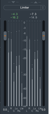
I/O Panel Meters
The Input and Output meters display Peak and RMS metering information.
- The current Peak value is displayed in white.
- The current RMS value is displayed in light grey.
The text readouts directly above the meters display the current Peak and RMS values.
Multiband Crossover Spectrum View
You can use the Multiband Crossover Spectrum View to select, adjust, and audition processing bands in mulitband modules. The following modules include multiband processing: Compressor, Exciter, Gate, and Transient Shaper. Each multiband module supports up to three adjustable processing bands.
| Icons | Control | Description |
|---|---|---|
|
|
ADD | To add Crossover Cutoff nodes, hover over the Crossover Cutoff node bar and click on the + button that appears. You can add up to 3 crossover regions. |
|
|
REMOVE | To remove Crossover Cutoff nodes, hover over the band area and click the x button. |
|
|
POWER BUTTON | Toggle ON/OFF to enable/disable processing for the cutoff section. |

|
SOLO | Enable to hear only the band selected. |
Gain Reduction Trace
Displays the amount of gain reduction being applied to the band.
Adjusting Crossover Cutoffs
You can manually adjust the multiband crossover points in the crossover mini- spectrum view using the following methods:
- CLICK & DRAG CUTOFF HANDLES
- Hovering over the crossover handle.
- Left-click and drag the handle left or right to the desired position.
- Use the frequency readout at the bottom of the handle while dragging as a reference to where the crossover point is in relation to frequency.
- ENTER TEXT INPUT
- Double-click on a crossover handle to open the readout as a text edit field.
- Type the desired frequency value for the crossover cutoff into this field.
- Hit the enter or return key to update the value.
NOTE: Crossover cutoff points are not shared
Crossover cutoff points are not shared across multiband modules. Adjusting a crossover point in one module will not affect the crossover points in other multiband modules.
Detection Filter View
Enable the Detection Filter to adjust the frequency response of the detection circuit. When the Detection Filter is active, you can access the controls outlined in the table and image below. Neutron 3 includes detection filter processing in only the Compressor module and Gate module.
| Icons | Control | Description |
|---|---|---|
|
|
Power Button | Toggle ON to enable the Sidechain Filter. By default the Detection Filter is OFF. |
|
|
Solo | Enable to audition the output of the Detection Filter. This can be useful to enable when adjusting the Detection Filter nodes. |

|
Resonant Filter Nodes | Adjusts gain and center frequency in lowpass bands and highpass bands. |
Resonant Filter Node Adjustments
The Resonant Filter Nodes are displayed within the the Detection Filter view. You can use these to tailor your frequency response:
- Click and drag the resonant filter nodes UP or DOWN to increase or decrease gain.
- Click and drag the resonant filter nodes LEFT or RIGHT to adjust the center frequency.
TIP: Compressor Detection Filter
- Making adjustments in the Detection Filter allows you to tailor the Compressor’s sensitivity to different frequencies. This is useful when using the Compressor in single band mode.
- For example: If you want the Compressor to react more to sibilant or harsh frequencies rather than low-frequency content, you can filter out low frequencies using the high-pass filter and boost sibilant frequencies using the resonant low-pass filter to adjust the signal that the Compressor treats as the input signal.
LFE (Low-frequency effects)
The LFE (Low-Frequency Effects) button only appears when Neutron 3 Advanced is loaded on 5.1 or 7.1 surround
tracks. LFE For more information on surround sound support, see the Surround Sound section
below.
You can find the LFE button for modules in the module header.

- Enable to include LFE in the audio processing. This is the default setting.
- Disable the LFE button to exclude low frequencies when passing audio through the Low Frequency Effects (LFE) channel with the relative latency compensation.
LFE Rolloff Filter
If you happen to be mixing to a surround-sound spec that requires a band-limited LFE signal, the 24 dB/octave LFE roll-off filter helps you achieve this. Access this filter in the Options Menu under the Metering Tab, where you’ll be able to enable the filter and select the cutoff value.
NOTE: LFE Rolloff Filter
This option only appears when Neutron is instantiated on a 5.1 or 7.1 surround track.
Surround Sound
Neutron 3 Advanced supports the following surround sound formats in the following hosts. Neutron processes all channels equally unless LFE processing is bypassed in any particular module.
| DAW | Surround Format | Channel Configurations |
|---|---|---|
| Pro Tools | Film | 1.0, 2.0, 3.0 (LCR), 4.0 (Quad), 5.0, 5.1, 7.0, 7.1 |
| Logic Pro | DTS, ITU/SMPTE, SDDS | 1.0, 2.0, 4.0 (Quad), 4.0 (LCRS), 5.1 (ITU/SMPTE) |
| Cubase | ITU/SMPTE | 1.0, 2.0, 3.0 (LRC), 3.0 (LRS), 4.0 (Quad), 4.0 (LCRS), 5.0, 5.1 |
| Nuendo | DTS, ITU/SMPTE, SDDS | 1.0, 2.0, 4.0 (Quad), 4.0 (LRCS), 5.0, 5.1, 7.0 (cine), 7.0 (music), 7.1 (cine), 7.1 (music) |
Surround Sound configuration in Neutron 3 will include LFE button and surround sound meters in the I/O panel as seen in the image below.
Assistants
Overview
Neutron includes two Assistant features aimed at intelligently and efficiently establishing a starting point for your mix or individual tracks, freeing you up to focus on creative mixing decisions. Choose either Mix Assistant or Track Assistant as starting points for your mixing session. We highly encourage using Track Assistant and Mix Assistant in your workflow to help you setup your mixing session.
Accessing An Assistant
Using the Assistants at the right time in your mix workflow is important so that you can get the most out of each assistant. In the Neutron 3 mothership, you can access either Assistant through the Mix Assistant button.
You will be given two choices:
- Choosing Balance option will bring up Mix Assistant.
- Choosing Track Enhance option will bring up Track Assistant.

TIP: Use Mix Assistant first for the best results
We suggest for you to use Mix Assistant before using Track Assistant since Mix Assistant helps you set up your session levels. Mix Assistant will provide you the most accurate results when you begin with a new, untouched session.
NOTE: Can't use Track Assistant and Mix Assistant at the same time
You cannot use Track Assistant and Mix Assistant simultaneously. However, neither of the Assistants will overwrite the other.
Mix Assistant
Neutron’s Mix Assistant helps you set up your mix, balancing the level of each element around your desired focus of the mix.
- You can access Mix Assistant either from Neutron 3 Advanced mothership plug-in or from Neutron 3 Visual Mixer plug-in.
- Mix Assistant can listen to and adjust the following IPC compatible iZotope plug-ins. See the table below to see which plug-ins are compatible to Mix Assistant.
| Plug-in | Access Mix Assistant | Mix Assistant Compatible |
|---|---|---|
| Neutron 3 Advanced mothership | ✓ | ✓ |
| Neutron 3 Standard mothership | X | ✓ |
| Neutron 3 Visual Mixer | ✓ | X |
| Neutron 3 Equalizer | X | ✓ |
| Neutron 3 Compressor | X | ✓ |
| Neutron 3 Exciter | X | ✓ |
| Neutron 3 Gate | X | ✓ |
| Neutron 3 Transient Shaper | X | ✓ |
| Neutron 3 Sculptor | X | ✓ |
| Relay | X | ✓ |
Recommended Workflow
Automatically set static level in all the tracks with Neutron 3 Advanced mothership, Neutron 3 components, and Relay. For best possible results, use Mix Assistant after you’ve imported raw stems (tracks) into a new session. We have two recommended workflows:
NOTE: Don't Touch Your Faders
Before you run Mix Assistant, check that the DAW faders are set to unity gain, i.e. don’t touch your DAW faders. The less you have set up, the easier it is for Mix Assistant to help you.
Mothership Workflow
In this workflow, the goal is to start your mix.
- Import all tracks needed for your session. The more tracks you include, the more useful Mix Assistant will be for you.
- Insert Relay as the first plugin on each track.
- Insert the Neutron mothership on any track you want.
- Click the Mix Assistant button. Select Balance and begin using Mix Assistant!
Visual Mixer Workflow
In this workflow, if you want Visual Mixer (exclusively) to set all your pans and faders, make sure to put Relay in the last insert on your tracks.
- Import all tracks needed for your session. The more tracks you include, the more time Mix Assistant will save you!
- Add Visual Mixer on your master bus. Know that Visual Mixer does not process audio, it just needs to know at least that there is activity occuring.
- Click on the Mix Assistant button in Visual Mixer and begin using Mix Assistant.
Mix Assistant Stages
Interacting with Mix Assistant involves the following stages:
In each stage, you need to perform an action that will help Mix Assistant provide you the most accurate results.

NOTE: Choose One Plug-in Per Audio Source
Use buses or individual tracks but don’t use both. While Mix Assistant can work on buses and individual tracks, you only need to exclusively use EITHER buses or individual tracks. If you have Neutron 3 Advanced and Relay all on the same track, you should only select ONE of these to represent the track.
TIP: Not Getting The Results You Want?
- Did you make sure you are only using individual tracks or buses? Mix Assistant was NOT designed to use BOTH individual tracks and buses.
- Did you make sure to set your faders and panning to unity gain?
- Did you make sure that you have the appropriate plug-ins set for Focus in the Setup stage?
- If you have more than one iZotope plug-in on any individual track or bus, make sure you selected only one of those plug-ins per track in the Setup stage.
1. SETUP
Select the tracks that are the focus of your mix and those that you want to include. Then, click Begin Listening.

This view lists all of the compatible iZotope plug-ins in your session. Make sure every track you want to include is represented and only included once. Do NOT play music during this stage!
NOTE: Select at Least One Track for Focus
You need to pick at least one focus of your mix. You cannot proceed to the next stage until you have done this. The focus is one instrument that you feel is the most important aspect of your mix. Many tracks can be the focus of your mix, for example, if there are two lead vocal tracks. However, if everything is the focus, then your Mix Assistant will not yield great results.
2. WAITING
Place the playhead at the beginning of your arrangement. Then, start the transport for the Assistant to begin listening.
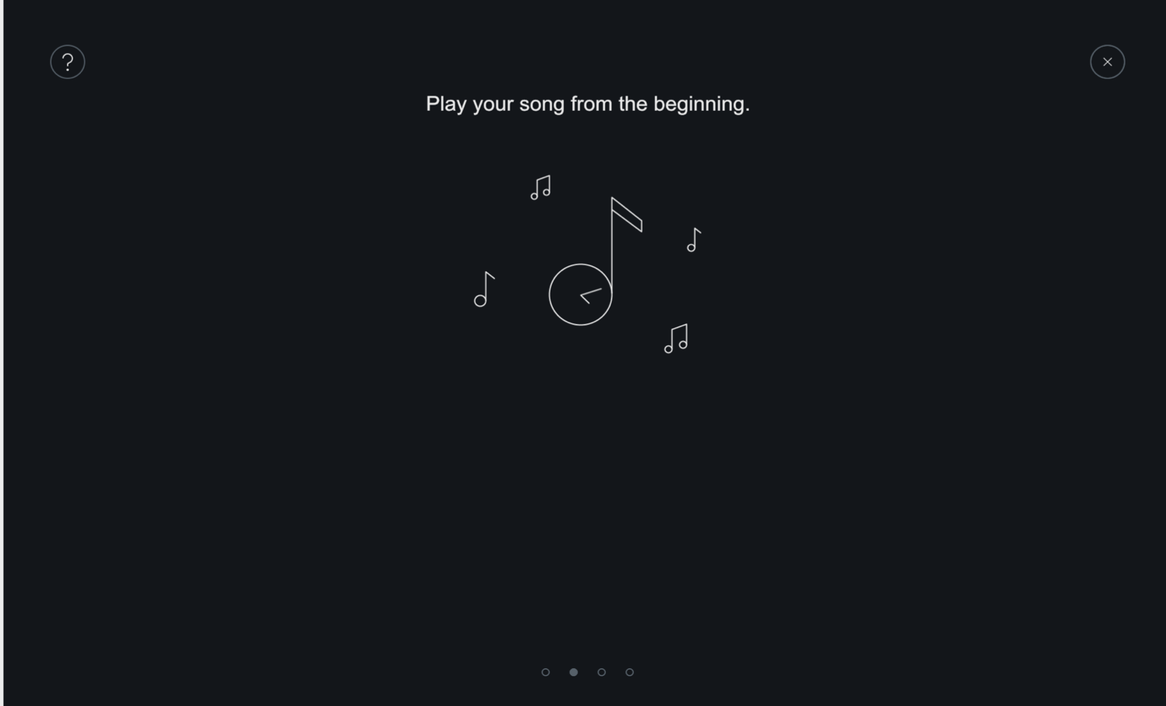
Mix Assistant can’t do anything without listening to your music. So, make sure you play your audio from where your audio starts wherever you want Mix Assistant to begin listening.
NOTE: Mix Assistant Will Not Listen To Already Playing Transport
If your transport is playing when you enter the Listening page, Mix Assistant will not begin listening automatically. You need to stop your audio and start the transport at the beginning of the song for best results. If using a large session, there may be a slight delay, try to start, rewind, and restart again.
3. LISTENING
When you reach the end of your session, click Go To Results to proceed to the results. If you don’t, Mix Assistant will never stop listening.

Mix Assistant listens to the overall level of each audio source and categorizes each instrument into groups.
4. AUDITION AND ADJUST
Now that Mix Assistant has listened and has categorized your audio, you can now:
- Audition the Mix Assistant’s suggestions.
- Adjust the Group Sliders to what sounds best to you.
- Compare Mix Assistant’s Results with your original session by clicking on the Bypass Assistant button.
- Edit the classifications of the Group Sliders and the Focus.
Group Sliders
Adjust the Group Sliders to your preference and audition the differences.
What are the Group Sliders?
The group sliders are created as a result of Mix Assistant listening to your audio. Mix Assistant gathers up all the information it has learned about your music and it sub-mixes these into the groups.
Mix Assistant determines a target level for the following groups:
- Focus: What you choose as the focus of your mix.
- Voice: Tracks selected with vocals.
- Bass: Tracks selected with bass.
- Percussion: Tracks selected with drums/percussion instruments.
- Musical: Other tracks that may not relate to the groups above.
Each group has an associated, adjustable level slider. The slider itself represents the overall gain differences of the groups relative to each other. When you adjust these sliders, you are making gain changes relative to Mix Assistant’s initial target level suggestion.
Mix Assistant will try to apply gain adjustment to each track within that group so that their combined levels achieve the target mix level set by the Group Slider.
The range of adjustment is +/- 12 dB for the Group Sliders.
TIP: Adjust Group Sliders to Taste
If you don’t like the way your mix sounds with the group sliders at their starting positions, they are not final–you can always experiment until you get the right level balance for your song.
Group Slider Behavior
Group Sliders will be disabled if there is no content recognized for that group. If all your audio sources are selected as the Focus, then only one slider (Focus slider) will be available. With that, any audio source that’s NOT used or classified is disabled.
Bypass Assistant
This button will disable the sliders and allow you to listen to your session pre-Mix Assistant suggestions.
Gain matching: when you’re auditioning Mix Assistant’s results, the unprocessed mix will be gain matched to the processed mix. By gain matching, you can better discern the differences in balance.

TIP: The Overall Level May Sound Quieter
To avoid clipping, we try to turn things down when trying to go for an overall mix, so the levels that Mix Assistant suggests may be lower than the original levels.
Edit
Edit which tracks are categorized for each Group by clicking on the “Edit Classifications” button in the lower right-hand corner. You can adjust the tracks in focus or reclassify the tracks. Mix Assistant adjusts the Groups to reflect your categorization decisions.

NOTE: MIX ASSISTANT'S EDIT PLUG-IN LIST
Any plug-ins that you did not select in the Setup stage will not appear in Mix Assistant’s Edit plug-in list. Also, you cannot add any plug-ins to that list. Additionally, if you add another track with one of the associated iZotope IPC plug-ins while Mix Assistant was in the Learning stage, it will not show up in the Edit track list.
5. ACCEPT
When you’re happy with the level balance of your mix, click Accept and your level settings will be applied to each source plugin using iZotope’s Inter-plugin Communication Technology (IPC).
- If you didn’t like anything, close out of the Mix Assistant window to revert the changes.
- If you auditioned the results, you can’t click Accept unless you disable Bypass Assistant.
TIP: View Output Gain Adjustments in Visual Mixer
You can see the adjustments made to the output gain sliders in every affected plug-in as shown in the results list. These changes are easiest to view in Visual Mixer component plug-in.
NOTE: Once You Close Out, You Can't Access Group Sliders
Once you close out of Mix Assistant, you cannot go back to the same screen to make group level changes. To make any Group Level changes, you will have to restart Mix Assistant from the beginning. Mix Assistant will re-learn everything unless you have overwritten a class which we will not alter.
Track Assistant
A handy customizable assistive tool that offers an intelligent starting point for an individual track, not the whole mix. Trained through machine learning, Track Assistant listens carefully to individual tracks and provides unique suggestions by dialing in different parameters within Neutron. You can then adjust Neutron 3 modules to your artistic taste.
Recommended Workflow
Track Assistant works on one track at a time and is not aware of the track’s context to your session. To use Track Assistant in your workflow:
- Insert a Neutron 3 mothership instance on a channel (track) that you want to apply Track Assistant to.
- Open the Neutron 3 mothership instance on one track and click on Track Assistant button.
- Choose the instrument, style and intensity for Track Assistant. You can also allow Neutron to figure out what your instrument is by choosing Auto-detect from the instrument’s dropdown menu.
- After you set Track Assistant, click Next.
- Hit the play button in your DAW, and Track Assistant will begin processing your audio.
- Check out the starting point Track Assistant suggested for you.
- Hit Accept to apply the results to your session!
NOTE: TRACK ASSISTANT PROCESSING TIME
When you use Track Assistant, it requires anywhere between 4 to 10 seconds of audio playback and analysis before it makes a decision on which settings to adjust. Neutron is inaccessible during Track Assistant processing.
Track Assistant Settings
Adjusting the Track Assistant settings gives a baseline for Track Assistant to help you find a starting point relative to your artistic vision. These settings affect parameters such as the amount of processing, the number of bands being processed, compression ratios, etc.
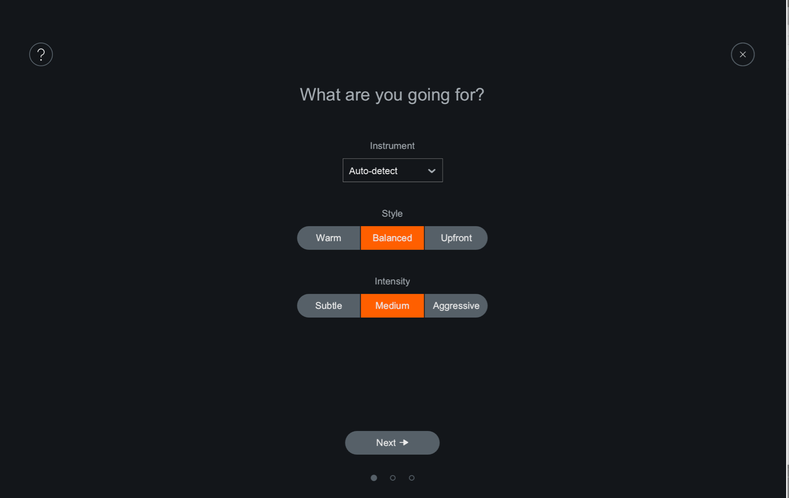
| Setting | Description |
|---|---|
| INSTRUMENT | Identifies the instrument classification which affects Track Assistant’s resulting parameter values and the default Sculptor mode. If you do not see your instrument listed, use either:Other: None of the above (e.g. Synths, Didgeridoo, Vuvuzela).Auto-Detect: let the Track Assistant auto-detect your instrument class. |
| STYLE | Suggests the aesthetic result that you might want to achieve. Balanced: Provides general-purpose processing for a well-rounded sound. Warm (open): Slightly emphasizes the bass in the instrument for a more pleasant sound.Upfront (midrange): Emphasizes the midrange frequencies of the instrument for more presence. |
| INTENSITY | Suggests the amount of processing you’re willing to allow Neutron to perform in order to get to the Style result you want.Low (subtle): Not a lot of processing added. Just a hint of adjustment to meet the Style. Medium: Moderate amount of processing added. Noticable change in bringing out that instrument. High (aggressive): Heavy amount of processing added to bring the instrument into focus. |
TIP: EXPLORE TRACK ASSISTANT SETTINGS
Play around with the different Track Assistant Settings if Track Assistant isn’t quite understanding what you’re looking for. Between Style and Intensity settings, there are 9 different combinations that influence the Track Assistant suggestions. With each combination, there are 6 presets—one per audio ID type. Thus, there’s a total of 54 unique and varied suggestions.
Track Assistant Processing
Track Assistant will process the audio based on the information gained from the settings and the incoming audio. Track Assistant will process this information in the following order:
- Track Assistant identifies your audio based on its instrument category.
- Track Assistant uses the audio identification to determine a signal flow preset (order of modules).
- Sets Target Curve in Sculptor module.
- Track Assistant determines a preset for how many bands each multiband capable module will have (minimum of one, maximum of three).
End Result: A unique preset including adjustments made to the signal flow, EQ curve, Compressor, Sculptor, and Exciter.
Track Assistant Effects on Modules
For each enabled multiband module, Track Assistant will place band crossover points depending on your audio. The most transparent crossover points are determined using a few criteria, including minima in the spectrum.
| Module | Track Assistant Adjustments |
|---|---|
| Equalizer | Determines a basic starting curve by enabling and placing filter nodes at optimal shelf points and at energy peaks throughout the spectrum. The filter node placement results in small boosts, cuts, static or dynamic behavior, or bell or shelving filter choices depending on your audio. Track Assistant places nodes at areas of interest already present in the signal. |
| Exciter | Uses Exciter presets to determine per-band Exciter parameters such as Tube/Tape/ Warm/Retro on the X/Y pad, and Dry/Wet Blend. Sets the Drive amount relative to the intensity of the input signal. |
| Compressor (x2) | For each enabled Compressor band, Track Assistant chooses thresholds dynamically based on an LKFS signal level analysis. This allows you to spend less time finding the sweet spot, and more time to make artistic decisions on the compressor effects. |
| Sculptor | Moved to first position of signal chain and sets a target curve based on your instrument selection in the main Track Assistant options page. |
| Gate | Removed from the signal chain. |
| Transient Shaper | Bypassed. |
INFO: HELP MAKE TRACK ASSISTANT BETTER!
If Track Assistant misidentifies your audio file, please send it to iZotope via Customer Care.
Gate
Overview
Use the Gate module to to eliminate or attenuate unwanted signal content when the input signal falls below a given threshold level.
Module Interface

Neutron 3 Gate module controls and features are outlined in the table below.
| Label | Section | Controls and Features |
|---|---|---|
|
|
Meters and Displays | Waveform Displays, Gain Reduction Trace |
|
|
Module Header | Multiband Crossover Spectrum View, Detection Filter View, Learn, Reset, LFE |
|
|
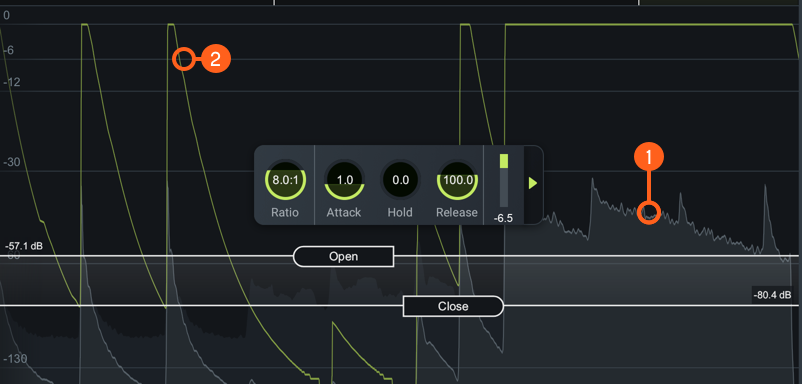
Interactive Controls | Open Threshold, Close Threshold |
|
|
HUD Controls | Ratio, Attack, Hold, Release, Gain Reduction Meter |
|
|
Advanced Panel | Sidechain |
Meters and Displays
The meters illustrate how the Gate is responding to and processing the input signal. The meters included are outlined in the image and table below.
| Label | Section |
|---|---|
|
|
Waveform Displays |
|
|
Gain Reduction Trace |
Waveform Displays
- Scrolling waveform: displays the amplitude of the input and output signals over time. The meter scrolls
from right to left, with the most recent information on the right.
- Input signal waveform: dark grey waveform displayed behind the output signal waveform.
- Output signal waveform: light grey waveform displayed in front of the input signal waveform. When the signal is gated, you can monitor the difference in the gain reduction applied to the output signal versus the input signal.
Gain Reduction Trace
Draws a line that represents the gain reduction applied to the selected band over time. Use the Gain Reduction Trace to monitor and to set the response times (attack and release) and gain reduction envelope applied over time.
Module Header
The controls in the module header affect the entire Gate module.

| Label | Section |
|---|---|
|
|
Multiband Crossover View |
|
|
Detection Filter View |
|
|
Learn |
|
|
Reset |
Multiband Crossover Spectrum View
Access the Multiband Crossover view and controls. See the Multiband Crossover View section in the General Controls chapter.
Detection Filter View
Access the Detection Filter view and controls. For more information, see the Detection Filter View below for information on each view.
Learn
Enable to allow Neutron to search for natural crossover cutoff points for multiband processing using a few criteria, including identifying minima in the frequency spectrum of the incoming audio. When it has determined and set the ideal values for the crossover cutoffs, it will turn itself off automatically. You can also manually disable learning when it is active by clicking the Learn button again.
Reset
Returns all controls in the Gate module to their factory default values. If you wish to return to settings you were using before clicking the Reset button, you can use the Undo History window to revert to the settings before the Reset event.
LFE
Appears when in surround sound configuration in a Neutron 3 Advanced mothership. Enabled by default to include LFE in processing. Disable the LFE button to exclude low frequencies when passing audio through the Low Frequency Effects (LFE) channel with the relative latency compensation. See the LFE section for more information.
Controls
You can control gating by setting the Open Threshold and Close Threshold. Click and drag the Threshold handles and place them where you want to apply gating.
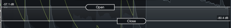
Open Threshold
Sets the level above which the gate will open, allowing the signal to pass through. When the input signal falls ABOVE the Open threshold level, attenuation will stop.
Close Threshold
Set below the Open threshold level at which the gate will close. This is also called hysteresis. When the input signal falls BELOW the Close threshold, it will be attenuated.
Adjusting Close Threshold
Moving the Close threshold either UP or DOWN will affect your gating. By setting Close threshold lower than Open threshold, more of the decay will pass without affecting the trigger threshold.
Tip: Reduce Chatter Effect
In some situations, undesirable signals that are near the level of the open threshold can cause the gate to “chatter” by crossing the threshold level too often. The Close threshold helps to eliminate this chattering effect. When a signal has dropped below the Close threshold, it will not trigger the gate to open again until it exceeds the level of the Open threshold.
HUD Controls
The HUD for the Gate Module includes:
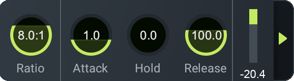
Ratio
Determines the amount of gain reduction applied to signals that fall below the Threshold.
Attack
Determines the amount of time (in milliseconds) it takes for the gate to transition from closed to open when a signal exceeds the Open threshold.
Hold
Sets the amount of time (in seconds) the gate will stay fully open after a signal falls below the threshold. The hold length will vary when the release period begins.
Release
Determines the amount of time (in milliseconds) it takes to transition from open to closed when a signal falls below the Close threshold.
Gain Reduction Meter
Displays the current average amount of gain reduction in decibels (dB) applied to the signal.
Advanced Controls
The Sidechain controls for the currently selected band are located in the Advanced panel of the HUD. To access the Advanced Panel, click the arrow button on the right hand side of the band HUD.
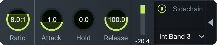
Sidechain
Allows you to trigger the amount of gain reduction in the Gate from a signal other than the input to the Gate. The signal is routed into the detection circuit of the Gate. You can choose either an internal or external input signal to trigger the Gate band’s dynamic behavior. By sidechaining, you can dynamically link elements of a mix to provide an adaptive balance between tracks.
Enabled Sidechain
When you enable Sidechain, you have the option to sidechain with an internal band or an external band. The sidechain dropdown menu will display active internal bands and active external instances categorized under internal or external as described in the list below.
- INTERNAL (INT.):
- Choose from any band currently placed in the Gate module.
- Using an internal sidechain input allows you to trigger gain reduction in the selected band from the amount of energy in a different band. For example, you can accentuate perceived low end energy by reducing high end any time the lowest band exceeds a defined threshold.
- Internal Full allows you to trigger gain reduction taking the sonic information from all active bands.
- EXTERNAL (EXT.):
- Choose from any audio from another track or bus.
- Using an external sidechain input will help balance a signal with other tracks.
- The external audio source can also be filtered through any of the bands in the Gate module by choosing any of the External bands (for example, Ext. Band 1).
Equalizer
Overview
An equalizer can be used to give you control over different parts of the frequency spectrum, independently allowing you to make character or corrective alterations by applying additive EQ or subtractive EQ.
Module Interface
Neutron 3 Equalizer module controls and features are outlined in the table below.

| Label | Section | Controls and Features |
|---|---|---|
|
|
Meters and Displays | Spectrum Analyzers, Composite Curve, Filter Response Curve, Meter Scales |
|
|
Module Header | Scale, Masking Meter, Soft Saturation, Learn, Reset, LFE |
|
|
Controls | Node Interactions, HUD Controls: General Band Controls, Filter Shapes, Readouts |
|
|
Advanced Panel | Dynamic Mode, Threshold, Sidechain |
Meters & Displays
The following meters and displays included in the EQ are outlined in the image and table below.

| Label | Section |
|---|---|
|
|
Spectrum Analyzers |
|
|
Composite Curve |
|
|
Filter Response Curve |
|
|
Meter Scales |
Spectrum Analyzers
Displays the magnitude (amplitude, in decibels) of the input signal across the frequency spectrum in real-time. Two spectrum analyzers are displayed in the EQ module to compare the effect of processing.
- Input signal: The input signal to the EQ module is shown as a dark grey spectrum with no border.
- Output signal: The processed output spectrum is drawn in the foreground with a white border.
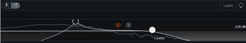
Composite Curve
Displays the combined filter response of all enabled bands. Represented by a thick white line drawn across the display. Adjusting EQ nodes will contribute to the overall shape of the composite curve.
Filter Response Curve
Displays the filter response of the currently selected node. Represented by a highlighted line and filled area under the band which appears when you select a node. If there are no nodes selected, the filter response curve is hidden and you will only see the composite curve.
Meter Scales
The Meter Scales are located on the left, right, and bottom of the spectrum window display. You can use these meter scales as a reference while making adjustments.
- Gain Scale (dB): displayed on the right side of the spectrum window.
- Spectrum Magnitude Scale (dB): displayed on the left side of the spectrum window.
- Spectrum Frequency Scale (Hz): displayed along the top of the spectrum window.
You can change the Frequency Scale measurements through the Scale menu, located in the Module Header or in Options under the EQ tab. Choose one of the Frequency Scale options to help you see different frequency distributions when placing your EQ nodes. The default scale is Extended Log.
| SCALE TYPE | DESCRIPTION |
|---|---|
| LINEAR | Displays an even view across all frequencies. This scale emphasizes the higher frequencies which can be useful for dialing in ‘air’ bands or EQ brightness. |
| MEL | Displays a frequency scale based on human perception of sound that visually corresponds to how we hear differences in pitch. |
| LOGARITHMIC, (FLAT, EXTENDED) LOGARITHMIC | Displays non-linear scales that offer detail on the low end and midrange, useful for the vast majority of EQ tasks. |
| PIANO ROLL | Uses default Extended Logarithmic scale while displaying a Piano Roll at the bottom of the EQ display to show the frequency and musical note relation. |
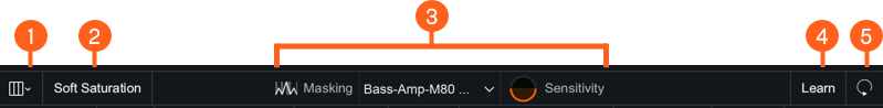
Module Header
The controls in the module header affect the overall resulting EQ module signal processing, but does not affect an individual band. The image and table below outline the controls in the Module Header.
| Label | Section |
|---|---|
|
|
Scale |
|
|
Soft Saturation |
|
|
Masking Meter |
|
|
Learn |
|
|
Reset |
Scale
Select a spectrum frequency scale option from the Scale Menu. See Meter Scales section for more information.
Soft Saturation
Enable Soft Saturation mode to excite the input signal generating subtle harmonics resulting in a fuller sound and subtle coloration by your EQ shaping.
Masking Meter
Enable to enter EQ into Masking Meter mode. Visit the Masking Meter chapter for more detailed information about the Masking Meter.
Learn
Enable Learn to quickly have EQ node placement suggestions based on intelligently identified areas of sonic importance in your audio signal such as sibilance, resonance, and rumble.
TIP: Learn Only Adjusts Enabled Bands
Learn will never remove or create an EQ band. Learn will only suggest adjustments for bands that are already present in the EQ module. Learn suggestions also do not affect Gain or Q. Once nodes are placed, you can hold the Shift key to preserve the frequency placement, and then move the gain up or down to determine if your track sounds better with that specific area of interest boosted or cut.
Reset
Returns all controls in the Equalizer module to their factory default values. If you wish to return to settings you were using before clicking the Reset button, you can use the Undo History window to revert to the settings before the reset event.
LFE
Appears when in surround sound configuration in a Neutron 3 Advanced mothership. Enabled by default to include LFE in processing. Disable the LFE button to exclude low frequencies when passing audio through the Low Frequency Effects (LFE) channel with the relative latency compensation. See the LFE section for more information.
Controls
Node Interactions
You can adjust bands by adding or removing nodes.
Add Bands
You can add bands in three different ways:
- Add on the Composite Curve: Hover over the white composite curve for a + button to appear. Click on the + button to add a node at the specific frequency on the composite curve.
- Add with Keyboard Shortcut: Hit command+ return (Mac) or ctrl+ return (Windows) to add a new node to the center of the EQ spectrum.
- Add anywhere on the Spectrum: Double-click anywhere in the EQ spectrum to add a new node at the location of the mouse.
NOTE: NODES WILL ADD CONTEXTUAL FILTER SHAPE
Depending on where you add a node, the node will appear with a pre-determined filter shape. There are three default contextual filter shapes that will be used when you add a new node:
- To the far left: Flat Highpass or High Shelf
- To the far right: Flat Lowpass or Low Shelf
- In the middle: Proportional Q
The Flat High Pass and the Flat lowpass will only be added once because you will typically only use one of each in either end of the spectrum. Otherwise, the node will default to a Shelf or Proportional Q filter shape.
Remove Bands
You can remove bands in three different ways:
- Remove Single band: Select a node and click the X button in the HUD to remove it.
- Remove Multiple bands: Click and drag to select multiple nodes. Use the delete or backspace key to remove all selected nodes.
- Remove with modifier keys: Shift+click to select multiple nodes. Use the delete or backspace key to remove all selected nodes.
HUD Controls
You can access a band’s HUD by selecting the band’s node. The HUD includes:
General Band Controls
The left side of the HUD includes parameters for enabling/disabling, soloing, and removing the currently selected band.
| Icon | Control | Description |
|---|---|---|

|
Power Button | Enables or disables processing of the currently selected band. |

|
Solo | Enables the selected filter to be listened to in isolation. |

|
Remove | Removes the band. |
NOTE: Bypassed filter response curve display
When a band is disabled, the filter response curve will still be displayed in the EQ module panel. Disabled bands are displayed in grey to clearly differentiate them from enabled bands.
NOTE: Using Alt-Solo and Band Solo
Use the following methods to solo a specific band or area of the frequency spectrum:
- Band Solo: Filters per-band. To access Band Solo, alt ( option) key and click on a node to solo the band. You can also use the Solo button in the HUD display to solo the selected band.
- Alt-Solo: Creates a moveable filter window allowing you to easily focus on the frequencies surrounding the location of the click. To access Alt-Solo hold the alt ( option) key and click anywhere on the frequency spectrum.
Band Filters
Use the table below to refer to the types of filters and associated filter shapes in the Filter Shape menu.
Filter Types
The EQ module features 13 different filter shapes, each one belonging to one of the following filter type categories: Pass Filter, Peak Filter, Shelf Filter.
| Filter Type | Description |
|---|---|
| Pass Filter | Used to attenuate frequency content that is below (for highpass) or above (for lowpass) a specified cutoff frequency. In the Lowpass and Highpass menu: Flat, Resonant. |
| Peak Filter | Used to boost or cut a specific center frequency level. In the Bell menu: Bell, Proportional Q, Band shelf. |
| Shelf Filter | Used to boost or cut the frequency content above or below a specified frequency. In the Low Shelf menu and High Shelf menu: Analog, Vintage, Baxandall. |
NOTE: Filters Dependent on Slope/Q Adjustments
Adjustment to the bandwidth (Q value) will determine the amount of boost/cut applied to frequencies around the center frequency. The slope of the filter defines the degree of applied attenuation.
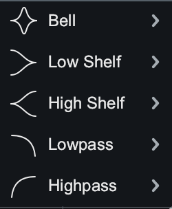
Filter Shapes
Choose from the Filter Shape menu to assign the filter shape of the selected band. The filter shape dropdown menu organizes the filter shapes into the following sub-menus: Bell, Low Shelf & High Shelf, and Lowpass & Highpass.
Bell
The Bell sub-menu includes the following Peak type filters:
| Shape | Description | When to Use |
|---|---|---|
Proportional Q
|
Unique filter that varies shape in proportion to the amount of boost or cut applied. As you increase or decrease the gain, the change is proportional to bandwidth where you will see the shape of the curve tightens with more extreme values of gain. | Tight, precise corrective cuts-the bigger gain adjustment, the tighter the cut will become. |
Bell
|
Smoothly boosts or cuts an adjustable region around a specific frequency. Looks like a bell, come on what do you want from me. | At larger gain adjustments (boost or cut), will change the overall color or texture of the sound. This will be a more noticeable change than Proportional Q. |
Band shelf
|
Bell filter with wide, flat top. | To change the relation between the harmonics in your audio. Useful for boosting or attenuating a block of frequencies. |
Low Shelf and High Shelf
The Low Shelf sub-menu and High Shelf sub-menu includes the following Shelf type filters:
| Shape | Description | When to Use |
|---|---|---|
Analog
|
Efficient shelf filter for simple boosts and cuts. Similar to standard shelf in an analog EQ. | To make noticeable boosts for making large changes in how bright or how bassy the content is. |
Baxandall
|
Inspired by the Baxandall EQ, with the addition of freely adjustable frequency.Low shelf: Gentle low frequency shelf.High Shelf: Gentle high frequency shelf. | Transparent way of addressing extreme lows and extreme highs for a more natural, gentle sounding effect. |
Vintage
|
Inspired by the renowned Pultec analog equalizer. Exhibits a complementary frequency dip, creating a complex slope with one node. | To fatten up low end without introducing muddiness. |
Lowpass and Highpass
The Lowpass sub-menu and Highpass sub-menu includes the following Pass type filters:
| Shape | Description | When to Use |
|---|---|---|
Flat 
|
Butterworth filter; optimized for maximum flatness without ripple or resonance in the passband or stopband (stability). | To transparently remove low end or high end frequency information without disturbing the character of the signal. Provides a clean, even, and natural sound. |
Resonant 
|
Filter equipped with a resonance control to emphasize the cutoff frequency with positive gain. | Boosting content at the cutoff frequency to add character and emphasize the lowest or highest part of the signal. |
NOTE: Gain and Q Adjustments
- Baxandall filter shape does not allow for Q adjustment.
- Lowpass and Highpass filter shapes do not allow for Gain adjustments.
Readouts
Use the HUD Readouts to see and adjust where the node is located within the EQ. The table below describes the readouts available with each readout’s respective units.
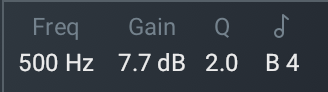
| Readout | Units | Description |
|---|---|---|
| Frequency | Hz | Shows the center frequency (or cutoff frequency) of the currently selected node. The EQ supports frequency values ranging from 20 Hz to 20 kHz. |
| Gain | dB | Shows the amount of gain applied by the selected filter. The EQ supports gain adjustments ranging from -30 dB to +15 dB. |
| Q | (cF/Bandwidth) | (Parametric/Bell Filters) Shows the width or slope of the selected filter. |
| Slope | (dB/octave) | (Highpass/Lowpass Filters) Shows the cutoff slope of the filter. |
| Musical Note | Note | Shows where the node is on the frequency spectrum in relation to the musical note. |
Adjust Frequency, Gain, and Q
There are 3 ways to adjust the Frequency, Gain, and Q:
- Click and drag EQ node or handles (for Q only).
- Manually enter the value.
- Use arrow keys.
Below outlines the three types of adjustments you can apply for altering the Frequency, Gain, and Q values.
| Value | Types of Adjustments |
|---|---|
| Frequency | Click and drag EQ node left to decrease the frequency or right to increase the frequency. Manually enter the value as described below. Use LEFT and RIGHT arrow keys. |
| Gain | Click and drag EQ node down to decrease the gain or up to increase the gain. Manually enter the value as described below. Use UP and DOWN arrow keys. |
| Q | Click and drag EQ node handles toward node to narrow the bandwidth or away from the node to widen the bandwidth.Manually enter the value as described below. Use alt/ option + arrow keys. |
To manually enter the value for Frequency, Gain, or Q:
- Double click on the value readout of the metric you wish to change.
- Type in the value desired in the text edit field.
- Hit enter or return to save the value adjustment.
TIP: Keyboard Modifiers For Value Adjustments
- Hold Shift key while clicking and dragging the node to lock the movement to the horizontal axis (for frequency) and vertical axis (for gain).
- Hold Shift while using the arrow keys to make coarse value adjustments.
- Hold the command key (Mac) or ctrl key (Windows) while using the arrow keys to make fine value adjustments.
NOTE: Reset All Band Parameters
You can reset all parameters for a particular band to their default values by double clicking on the node.
NOTE: EQ Gain Scale
Use the EQ Gain scale, located on the right edge of the EQ module display to reference dB magnitude while adjusting nodes.
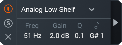
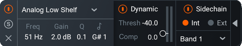
Advanced Panel
To access the Advanced Panel, select a node and click the Advanced Panel arrow on the right hand side of the band HUD. The Advanced Panel includes the following Advanced controls for the EQ module:
NOTE: Advanced Controls ON
If no Advanced Controls are active, the Advanced Panel arrow displays white. If you actively engage the Advanced Controls (Sidechain or Dynamic Mode), you can click the white arrow to close or minimize the Advanced Controls Panel. In this case, the the Advanced Panel arrow displays orange.
Dynamic Mode
Enable to apply dynamic variable gain to the selected node in relation to the threshold setting. Enables you to either to boost or to attenuate the signal once the signal crosses the threshold. The threshold defines the point at which attenuation or boosting can occur.
NOTE: Highpass and Lowpass Don't Support Dynamic mode
All filter types except for Highpass and Lowpass filter types support dynamic mode. When using either Highpass or Lowpass filter shapes, the Dynamics menu in the HUD will be greyed-out and not accessible.
Threshold
Sets the signal level at which dynamic gain adjustments will be triggered for the selected EQ node. You can set the Dynamic threshold in three ways:
- Click and drag the slider to the desired value.
- Click on the slider and use the UP or Down arrow keys to increase or decrease the value.
- Double-click on the Threshold readout and type the value into the inline edit field.
Threshold Meters
There are two meters associated with the Threshold control:
- Input Level Meter: Displays the input signal of the selected node.
- Band Reduction/Band Addition Meter: Displays the amount of dynamic level adjustment applied by the selected band.
Dynamic Mode Direction
When you enable Dynamic mode, you can control the Dynamic Mode Direction which determines the direction of gain change (UP or DOWN) using the Up/Down controls. The Up/Down controls will appear directly above and below the associated EQ node.
UP
Select the Up arrow to increase the gain of the filter when signals exceed the Threshold level.
- When the EQ node is placed above the zero line, the filter will be set to 0 dB of gain until it is triggered. When it is triggered by incoming signals exceeding the threshold, the gain of the filter will be increased in the direction of the node
- When the EQ node is placed below the zero line, the gain of the filter will be increased toward the zero line when it is triggered by incoming signals exceeding the threshold.
DOWN
Select the Down arrow to decrease the gain of the filter when signals exceed the Threshold level.
- When the EQ node is placed above the zero line, the gain of the filter will be reduced toward the zero line when triggered.
- When the EQ node is placed below the zero line, the filter will be set to 0 dB of gain until it is triggered. When it is triggered by incoming signals exceeding the threshold, the gain of the filter will be reduced in the direction of the node.
Sidechain
Controls the amount of compression or expansion by choosing either an internal or external input signal to trigger the EQ node’s dynamic behavior. By sidechaining, you can alter or improve the relationships between the elements of the mix so that they work together.
NOTE: Default Sidechain Routing
The default Sidechain input, when you first enable the sidechain, is the band you have currently selected. For example, node 5 would default to a sidechain of Internal Band 5. This processing is equivalent to Dynamic mode with Sidechain disabled.
Enabled Sidechain
When you enable Sidechain, you have the option to sidechain with an internal band or an external band.
- INTERNAL (INT.): Choose from any band currently placed in the EQ module.
- Using internal sidechain will help balance a signal within itself.
- Internal Full will take the full bandwidth of the audio signal.
- EXTERNAL (EXT.): Choose from any audio from another track or bus.
- Using external sidechain will help balance a signal with other tracks.
- The external audio source can also be filtered through any of the bands in the EQ module by choosing any of the External bands (for example Ext. Band 1).
SIDECHAIN WITH BYPASSED NODES
Even if a node is bypassed, it can be used as a sidechain to any other node—set its frequency and Q as you would for any enabled band.
Masking Meter
Overview
Neutron’s Masking Meter can be used to quickly and easily see where there are tracks competing for space in your mix, potentially contributing to a lack of clarity, a muddy sound, or masking.
What is Masking?
By definition, masking is a psychoacoustic phenomenon that occurs when two sounds occupy the same (or similar) frequency ranges and become indistinguishable. When masking appears in a mix, masking can cause your tracks to lose definition and clarity due to multiple sounds fighting for attention in a similar frequency range.
PROBLEM WITH MASKING
Masking can make it difficult to discern audio that needs sonic separation or space. In general, masking can be either encouraged or problematic (but not bad) depending on its context:
- Encouraged masking: when two sources blend there is likely some overlap in a frequency range, and therefore some amount of masking happens. This is similar to the use of distortion in mixing.
- Problematic masking: when two sources blend, but their frequencies tend to obscure rather than compliment each other. This can be frustrating because it is difficult to listen, analyze, and understand where tracks compete across an entire mix.
USING THE MASKING METER
Dedicated iZotopians took the time to establish a proprietary psychoacoustic masking hypothesis of what problematic masking might be, and subsequently how to visualize potential problem areas for you to consider when equalizing (Please see (AES 141, Paper 53)1 for more details.).
Neutron 3 includes our Masking Meter technology which shows you in real time:
- Areas of the frequency spectrum where masking is occurring (Masking Meter).
- Frequency regions in which there are multiple instances of masking over time and that are worthy of attention (Masking Histogram).
These tools simply show where masking is occurring. It is up to you to determine when this masking is problematic and requires further action.
MEASURING PROBLEMATIC MASKING
In simple terms, Neutron’s Masking Meter takes two audio inputs:
- A source (the active plug-in instance)
- An external input “masker” (the plug-in selected in the Masking Meter drop-down menu)
The Masking Meter uses a model of the outer/middle ear to calculate perceptual loudness of each signal, as well as their loudness relative to one another. The source’s loudness loss due to the masker is then calculated as:
Loudness Loss = Perceived loudness [phons] - Perceived partial loudness [phons]
This calculation is strictly based on the intricacies of human hearing and perception. For more information on this calculation, please see AES 141, Paper 531
Masking Meter Interface
Neutron 3 Masking Meter controls and features are outlined in the table below.
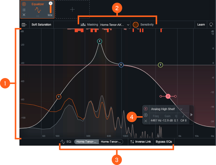
| Label | Section | Controls and Features |
|---|---|---|
|
|
Meters and Displays | Spectrum Displays, IPC Spectrum Displays, Masking Meter, Masking Histogram |
|
|
Masking Meter Controls | Masking Meter Dropdown Menu, Masking Sensitivity |
|
|
EQ Masking Controls | EQ Toggle, Bypass EQs, Inverse Link |
|
|
HUD Controls | General Band Controls, Filter Shapes, Readouts, Advanced Panel |
Meters and Displays
The meters and displays show how Masking Meter is responding to and processing the input signal:
Spectrum Displays
The spectrum displays of the Masking Meter are the same as those in the Equalizer module. See the Meters & Displays section in the Equalizer chapter for more information.
IPC Spectrum Displays
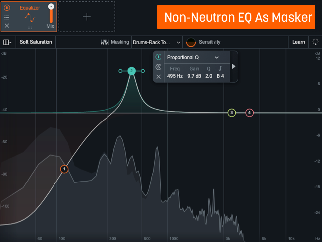
This display only appears when connected to a Neutron 3 mothership or EQ component plug-in instance. Depending on the IPC instance you choose to compare with your current Neutron instance, you will see two different displays:
- NEUTRON EQ AS A MASKER:
- Any Neutron 3 instance or component plug-in that has an EQ.
- Displays Masking Meter, Masking Histogram, EQ Masking Controls, and EQ Composite Curve.
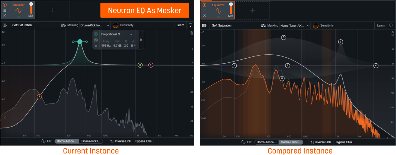
- NON-NEUTRON AS A MASKER:
- Any compatible iZotope IPC plug-in.
- Displays Masking Meter and Masking Histogram with no EQ controls.
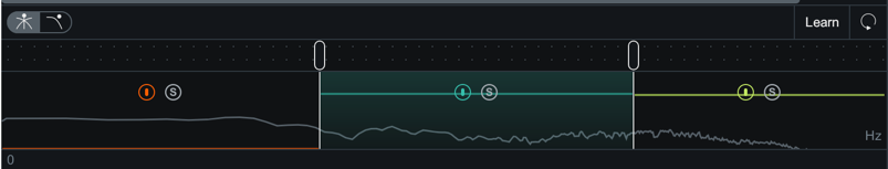
Masking Meter

Displays the highlighted areas of the spectrum to indicate where there is momentary masking (loudness loss) in the frequency domain. The brighter the highlights, the more masking is occurring in that area.
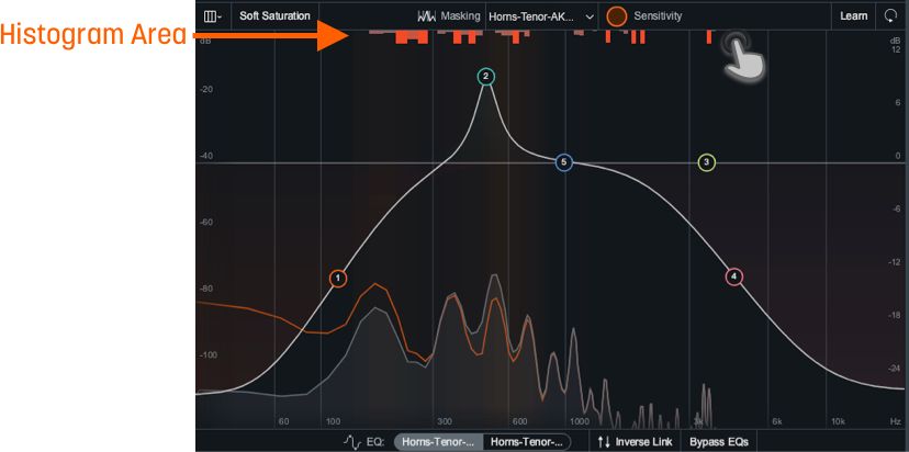
Masking Histogram

Displays a cumulative representation of frequency collisions—points of extreme masking—occurring in each critical band over time by filling in the histogram meter with a red color. The more collisions, the more the histogram meter is filled. This provides a zoomed out view of where masking occurs most over a longer period of time.
How the Masking Histogram Works
Masking Histogram counts the number of frequency collisions in each critical band. When the loudness loss in a particular frequency band is over a pre-determined threshold, we consider it extreme masking and tag it as a “collision.” These collisions are represented as a bar extending from the top of the module view. The further they extend down, the more collisions are occurring in those bands.
NOTE: MASKING HISTOGRAM IS A SUGGESTION
Use the results of the Masking Histogram as a suggestion of where there is masking occurring rather than a prescriptive message that you need to fix that area. Masking does not always need to be eliminated, but it is helpful to know where it is when making EQ decisions.
NOTE: Collision Histogram Peak Hold Time
The Masking Histogram is a real-time meter. The peak hold times (found in the Options window) adjust the calculation window between three values of 400 ms, 3,000 ms (default), and Infinite.
Clearing collisions and events
Click once anywhere in the Histogram Area to clear all events in the Masking Histogram.
TIP: MASKING HISTOGRAM AS CLIP INDICATOR
The Masking Histogram can act like a clip indicator—for each frequency band, it shows whether or not extreme masking has occurred. However, unlike a clip indicator, the Masking Histogram counts the number of collisions rather than just showing that at least one instance of clipping has occurred. The more collisions that have occurred in a band, the more its bar grows to bring your attention to problem areas.
Masking Meter Controls
The main masking meter controls in both non-Neutron EQ as a Masker and Neutron EQ as a Masker are outlined in the image and table below.

| Label | Section |
|---|---|
|
|
Masking Meter Dropdown Menu |
|
|
Masking Sensitivity |
Masking Meter Dropdown Menu
Displays all compatible iZotope plug-ins in your session. When you select one of these instances, the Masking Meter and Masking Histogram will compare the amount of masking (loudness loss) between the selected instance and your current track.
NOTE: Disable automation in remote instances
When making changes to the target EQ, it’s actually sending those changes to the other plug-in. For this reason, adjustments to this second EQ may behave unpredictably with automation. That’s why we recommend not applying automation on a remote EQ instance.
Masking Sensitivity
Scales the threshold used to determine whether loudness loss is extreme enough to count as a collision (and therefore show up in the Masking Histogram).
- At high sensitivity, smaller amounts of loudness loss count as collisions and it will appear that more masking is occurring since the Masking Histogram will fill up more quickly. If you’re seeing no masking but hearing muddiness, it could help to turn the sensitivity up until you see some activity in these meters.
- At low sensitivity, fewer collisions will appear on the Masking Histogram since the loudness loss thresholds will be much higher. Turning down the sensitivity will help show you the most extreme amounts of masking between your tracks.
The range of loudness loss displayed in the Masking Meter is similarly affected by the Masking Sensitivity control.
- At higher sensitivity, a lower amount of loudness loss appears on the meter
- At lower sensitivity, a larger loudness loss is required to show high amounts of masking (brighter colored lines).
NOTE: MASKING SENSITIVITY FOR METER ONLY
Any adjustments to Masking Sensitivity will not make any adjustments to audio processing. Even though it may seem that masking has decreased when the masking sensitivity is turned down, it is merely that the sensitivity of the meter has been adjusted.
TIP: USE GAIN OFFSET FOR ACCURATE MASKING CALCULATIONS
Masking calculations are sensitive to the levels of each track. If you apply a DAW’s track pre-fader, a Neutron instance will not know about this gain change. This directly affects Neutron’s masking calculations. To get the most accurate masking calculations, we recommend setting each Neutron instance’s Gain Offset amount to the same value as the DAW’s track pre-fader. It will not in any way affect the audible gain of Neutron, simply the levels at which masking is calculated.
LFE
Appears when in surround sound configuration in a Neutron 3 Advanced mothership. Enabled by default to include LFE in processing. Disable the LFE button to exclude low frequencies when passing audio through the Low Frequency Effects (LFE) channel with the relative latency compensation. See the LFE section for more information.
EQ Masking Controls
The EQ masking mode controls are outlined in the image and table below.

| Label | Section |
|---|---|
|
|
EQ Toggle |
|
|
Inverse Link |
|
|
Bypass EQs |
EQ Toggle
Switch between your active Neutron instance and the other IPC EQ instance to view and alter the EQ settings in the selected view.
Bypass EQs
Enable to bypass both the source and the target EQ modules.
TIP: USE BYPASS TO COMPARE ACROSS TRACKS
When doing any equalization, particularly across multiple tracks, it’s especially important to always check the Before/After to ensure that the changes you’re making are helping, not hurting, your mix. Use Bypass to help you determine these changes between tracks.
Inverse Link
Links a node’s Gain and Frequency to another node that is relatively close in frequency from the comparing EQ instance. If Inverse Link chooses a node with a different filter shape, Inverse Link will set the shape of that node to match.
TIP: Use Inverse Link for Subtle Changes
Rather than making big, sweeping changes to one track, the goal is to achieve optimal separation with subtle changes to each individual track, such as boosting and cutting each by 1.5 dB rather than boosting or cutting just one by 3 dB. Inverse Link can be toggled ON and OFF to suit any workflow.
NOTE: Inverse Link Controls Gain and Frequency Only
Inverse Link does not control any other aspect of that particular node (e.g. Q, Filter type, Dynamic/Static). Although you may wish to share cuts, boosts and frequency positions, it’s rare that you’d also want to use identical Q in both tracks. It’s best practice to cut with narrower Qs and boost with broader, more gentle shapers, to avoid resonance.
Compressor
Overview
A compressor can be used to reduce dynamic range, maintain consistent levels, and shape the tone and character of your audio.
Module Interface
The Neutron Compressor module includes the following sections:

Module Header
The controls in the module header affect all enabled bands in the Compressor module.

- Vintage Mode
- Views
- LFE: Surround instances only.
- Level Detection mode
- Auto Gain & Auto Release
- Output Gain
- Learn
- Reset
Vintage Mode
Enable to switch from the default digital mode to vintage signal processing which offers less transparent, more lively and colorful sound.
TIP: VINTAGE MODE AND HIGH RATIOS
By applying high ratios, you can achieve a pumping effect. Although not always desired, this can be used to add character to your audio. This effect is particularly useful on room mics.
Views
You can switch between the following views in the Compressor:
Multiband Crossover Spectrum
Access the Multiband Crossover Spectrum View and controls. For more information, see the Multiband Crossover Spectrum View.
Detection Filter
Access the Detection Filter view and controls. For more information, see the Detection Filter View section.
LFE
This option appears when Neutron is inserted on a 5.1 or 7.1 surround track. When enabled, the LFE channel will be processed along with all other channels. When disabled, the LFE channel will not be processed by the associated module. If necessary, latency compensation is applied to the LFE channel when it is disabled, to ensure timing is maintained between all channels.
Level Detection Mode
Determines how input levels are calculated by the compressor. Adjusting the level detection mode will alter the level that is considered by the threshold, which will affect when or how often the input level will trigger compression. The Compressor includes three level detection modes:
- RMS (Root Mean Square): Determines input level to the compressor by averaging levels of the incoming signal. RMS detection is useful when you are trying to increase the overall volume level without changing the character of the sound.
- PEAK Determines the input level to the compressor using instantaneous peak levels of the incoming signal. In general, this setting is useful when you are trying to even out sudden transients in your music.
- TRUE Similar to RMS mode, True peak mode determines input level to the compressor by averaging levels of the incoming signal, but produces even levels across all frequencies. True mode will not produce aliasing or artifacts- a common side-effect of RMS detection.
Auto Gain
Enables the Compressor to calculate the level difference between the input (uncompressed signal) and output (compressed signal) and automatically apply the calculated gain adjustment.
Auto Release
Enables the Compressor to analyze the input signal in order to automatically scale the Release time to values that will help to avoid pumping and maintain desired loudness in the processed signal.
NOTE: Auto Release Enabled with Vintage Mode
Auto Release is always enabled when Vintage Mode is selected.
Output Gain
Allows you to adjust the amount of gain applied to the signal after compression, to make up for any loss or increase in level caused by dynamics processing.
- This is also useful for managing the signal level as it passes to the input of the next module in the signal chain.
- When using Compressor 1 and Compressor 2 in series, adjusting the output gain of Compressor 1 allows you to manage the signal level going into Compressor 2, allowing for greater control over how Compressor 2 affects your sound.
Learn
Enables the Compressor to search for natural crossover cutoff points for multiband processing. The Learn button will be disabled if only one band exists in a multi-band capable module.
NOTE: LEARN WILL DISABLE WHEN DONE
After Learn determines and sets the ideal values for the crossover cutoffs, it will turn itself off automatically. When Learn button is toggled OFF the button is grey instead of orange. You can also manually disable Learn when it is active by clicking the Learn button again.
Reset
Returns all controls in the Compressor module to their factory default values. If you wish to return to settings you were using before clicking the Reset button, you can use the Undo History window to revert to the settings before the reset event.
Meters and Displays
The main visualizations in the Compressor module include the following:
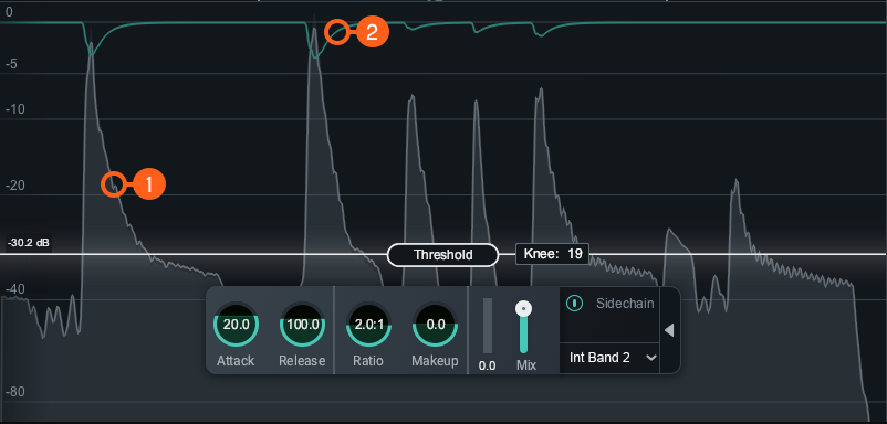
- Waveform Displays:
- Scrolling waveform: displays the amplitude of the input (uncompressed) and output (compressed) signals over time. The meter scrolls from right to left, with the most recent information on the right.
- Input waveform: the dark grey waveform displayed behind the output (wet) signal waveform.
- Output waveform: the light grey waveform displayed in front of the input (dry) signal waveform. When the signal is compressed, you can monitor the applied gain reduction compared to the input.
- Gain Reduction Trace: Draws a line that represents the gain reduction applied to the selected band over time. Use the Gain Reduction Trace to monitor and to set the response times (attack and release) and gain reduction envelope applied over time.
NOTE: AUTO GAIN ON THE OUTPUT WAVEFORM
Auto Gain adjusts the level of the compressed signal to compensate for any level difference between the uncompressed and compressed signals. The gain change introduced by auto gain is reflected in the output waveform, which may make it more difficult to differentiate between the input and output waveforms. The gain reduction trace meter can be useful for monitoring gain reduction over time when Auto Gain is enabled.
Controls
You can control compression by setting the Threshold and Knee.

Threshold
Determines the signal level at which the compressor begins processing.
- ADJUSTING THRESHOLD:
- Click and drag the Threshold slider handle up to increase the Threshold or down to decrease the Threshold.
- Click on the Threshold value readout text and manually enter a value in the inline edit field.
TIP: USE WAVEFORM DISPLAYS TO SET THRESHOLD
You can use the Waveform Displays as a visual guide when setting the threshold level for the compressor.
Knee
Adjust the knee value to set the desired character of the compression. The range of knee values provide different results:
- Higher knee values result in a “soft knee” setting with a subtle, natural sounding compression.
- Lower knee values result in a “hard knee” setting with an aggressive compression.
NOTE: Knee disabled in Vintage Mode
The Knee control is not adjustable when Vintage Mode is enabled.
HUD controls
The Compressor HUD controls work together to influence the character, amount, and speed of the compression applied to the input signal. The HUD controls available are:

Attack
Determines the amount of time it takes (in milliseconds) for the signal to become fully compressed after exceeding the threshold level.
Release
Adjust the amount of time (milliseconds) it takes for the Compressor to return to unity gain (recovers gain) when the input signal falls below the threshold, according to the rules set by the Level Detection Mode.
Ratio
Determines how much gain reduction will be applied to the entire signal or entire band when the threshold is crossed, according to the rules set by the Level Detection Mode.
NOTE: RATIO SETTINGS AFFECT COMPRESSION
Certain ratio settings and threshold setting will affect compression:
- A ratio setting of 1:1 will cause no attenuation upon signals that exceed the threshold.
- Ratio settings of 10:1 or greater will cause the compressor to function as a limiter.
- A ratio above 1.0 will cause compression. But, if you have a ratio below 1.0, it will cause the module to function as an Expander. When performing expansion in this way, the Gain Reduction Meter will show an inverted meter display.
Gain Reduction Meter
Displays the current instantaneous amount of gain reduction in decibels (dB) applied to the signal.
Makeup Gain
Determines the amount of static gain applied to the output signal after compression.
Mix
Adjust this slider to control the dry/wet mix of the direct, unprocessed signal with the processed signal for the associated band.
Advanced Controls
The Sidechain controls for the currently selected band are located in the Advanced panel of the HUD. To access the Advanced Panel, click the arrow button on the right hand side of the band HUD.
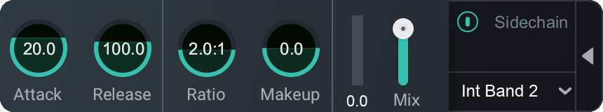
Sidechain
Allows you to trigger the amount of gain reduction in the compressor from a signal other than the input to the compressor. The signal is routed into the detection circuit of the compressor. Sidechained signal levels will control the amount of compression as defined by the threshold level. You can choose either an internal or external input signal to trigger the Compressor band’s dynamic behavior. By sidechaining, you can alter or improve the relationships between the elements of the mix so that they work together.
Enabled Sidechain
When you enable Sidechain, you have the option to sidechain with an internal band or an external band. The sidechain dropdown menu will display active internal bands and active external instances categorized under internal or external as described in the table below.
- INTERNAL (INT.): Choose from any band currently placed in the Compressor module.
- Using an internal sidechain input allows you to trigger gain reduction in the selected band from the amount of energy in a different band. For example, you can accentuate perceived low end energy by reducing high end any time the lowest band exceeds a defined threshold.
- Internal Full allows you to trigger gain reduction using the sonic information from all active bands.
- EXTERNAL (EXT.): Choose from any audio from another track or bus.
- Using an external sidechain input will help balance a signal with other tracks.
- The external audio source can also be filtered through any of the bands in the Compressor module by choosing any of the External bands (for example, Ext. Band 1).
Transient Shaper
Overview
Transient Shaper can be used to transparently alter and shape your sound’s attack and sustain characteristics while enhancing the sound’s presence without affecting the overall level.
Module Interface
The Transient Shaper module includes the following sections:

Meters and Displays
Meters and diplays illustrate how the Transient Shaper is responding to and processing the input signal.

Waveform Displays
- Input signal waveform is displayed in dark grey, behind the output signal waveform.
- Output signal waveform is displayed in light grey, in front of the input signal waveform.
Gain Envelope Trace
Displays the incoming signal with a superimposed colored curve that indicates the amount of gain adjustment applied in real time when you’re shaping an envelope.
TIP: Monitor With Gain Envelope Trace
Use the Gain Envelope Trace to monitor and to set the response times (attack and release) and gain reduction envelope applied over time. It can show the effect of changing envelope modes can have on allowing audio to return to 0 dB of gain before the next transient, is an important tool when seeking to achieve maximum transparency.
Module Header

- Multiband Crossover Spectrum View: Access the Multiband Crossover Spectrum View and controls. For more information, see the Multiband Crossover Spectrum View chapter.
- Envelope Modes
- Learn
- Reset
- LFE (not pictured, surround instances only.)
Envelope Modes
Determines the type of ADSR envelope settings to apply. Choose from three different Envelope modes:
- PRECISE: Fastest recovery time to next transient. Most accurate and responsive when adding or removing attack to a signal.
- BALANCED: Middle of all three modes. Quick attack and a medium release time when recovering from one transient to the next.
- LOOSE: Slowest transient recovery time and adds large amounts of sustain.
Learn
Enable Learn in the multiband mode to quickly have natural crossover cutoff points using a few criteria and minima in the spectrum. Placement suggestions are based on intelligently identified areas of sonic importance in your audio signal such as sibilance, resonance, and rumble.
NOTE: LEARN WILL DISABLE WHEN DONE
After Learn determines and sets the ideal values for the crossover cutoffs, it will turn itself off automatically. When Learn button is toggled OFF the button is grey instead of orange. You can also manually disable Learn when it is active by clicking the Learn button again.
NOTE: LEARN REQUIRES ACTIVE INPUT AUDIO
For learning to behave as expected, the module must be receiving audio input while Learn is engaged. The Learn button will be disabled if only one band exists in a multi-band capable module.
Reset
Enable Reset to revert the entire Transient Shaper module back to factory default. If you wish to return to settings you were using before clicking the Reset button, you can use the Undo History window to revert to the settings before the Reset event.
LFE
This option appears when Neutron is inserted on a 5.1 or 7.1 surround track. When enabled, the LFE channel will be processed along with all other channels. When disabled, the LFE channel will not be processed by the associated module. If necessary, latency compensation is applied to the LFE channel when it is disabled, to ensure timing is maintained between all channels.
HUD Controls
The controls in the Transient Shaper module work together to customize your sound’s shape. The following controls are available in the Transient Shaper HUD:

Attack
Adjusts the amount of level (decibels) applied to the initial transient.
- Increasing Attack results in an exaggerated and punchy sound.
- Decreasing Attack results in a softer, warmer sound.
Contour
Control the per-band response across a multiband spectrum of Transient Shaper:
| Shape | Description | |
|---|---|---|

|
SHARP | Fast and tight release time. Useful for short and staccato audio. |

|
MEDIUM | Transparent and linear release envelope. Useful on most audio. |

|
SMOOTH | The slowest envelope of all modes and allows more of the initial transient through to affect Sustain in a gentle way. Useful for sustained audio. |
Sustain
Adjusts the amount of level (decibels) applied to the sustain of the transient.
- Increasing Sustain results in a dense, airy sound.
- Decreasing Sustain results in tighter, more aggressive sound.
Gain Difference Meter
Displays the current average amount of gain in decibels (dB) applied to the signal.
Exciter
Overview
The Exciter can be used to add harmonic distortion to enhance and accentuate elements in your audio.
Module Interface

Neutron 3 Exciter module controls and features are outlined in the table below.
| Label | Section | Controls and Features |
|---|---|---|
|
|
Meters and Displays | Spectrum Displays |
|
|
Module Header | Multiband Crossover Spectrum View. Pre-Emphasis Modes, Learn, Reset, LFE |
|
|
Controls | Post Filter, HUD Controls, Drive, X/Y Pad, Mix |
Meters & Displays
Meters and displays illustrate how the Exciter is responding to and processing the input signal. The image below shows the Spectrum Displays.
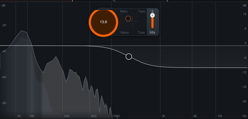
Spectrum Displays
- Spectrum Analyzer: displays the magnitude (amplitude vs db) of the input and output signals across the
frequency spectrum in real-time.
- Input signal spectrum displays a dark grey spectrum behind the output.
- Output signal spectrum: displays a light grey spectrum, in front of the input signal.
- Northern Lights: Displays highlighted areas of the spectrum to indicate where saturation is applied.
Module Header
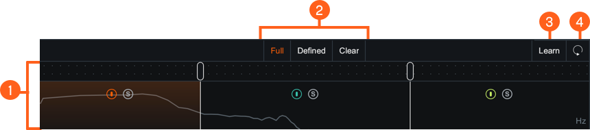
| Label | Section |
|---|---|
|
|
Multiband Crossover Spectrum View |
|
|
Pre-Emphasis Modes |
|
|
Learn |
|
|
Reset |
Multiband Crossover Spectrum View
Access the Multiband Crossover Spectrum View and controls. For more information, see the Multiband Crossover Spectrum View section.
Pre-Emphasis Modes
Use to apply apply subtle harmonic emphasis to saturation in different areas of the frequency spectrum. These differences allow mild changes to the low-mids (vocal thickness or body) or high-mids (vocal presence). The types of Pre-Emphasis Modes available to you are:
- FULL: low-mid frequency bump
- DEFINED: high-mid frequency bump
- CLEAR: gentle, low-mid frequency attenuation
Learn
Enable Learn to allow the Exciter to quickly identify natural crossover cutoff points and provide cutoff placement suggestions based on intelligently identified minima in the spectrum.
Reset
Enable Reset to revert the entire Exciter module back to factory default. If you wish to return to settings you were using before clicking the Reset button, you can use the Undo History window to revert to the settings before the Reset event.
LFE
Appears when in surround sound configuration in a Neutron 3 Advanced mothership. Enabled by default to include LFE in processing. Disable the LFE button to exclude low frequencies when passing audio through the Low Frequency Effects (LFE) channel with the relative latency compensation. See the LFE section for more information.
Controls
Post Filter
Applies gentle shelving for attenuation. Displayed as a high shelf icon as high shelf icon overlaid on the multiband spectrum view.
| Post Filter Adjustments | Ranges |
|---|---|
| Maximum Attenuation | -12dB |
| Frequency Range | 1kHz to 20kHz |
Drag the Post Filter node to adjust the frequency and the gain of the filter.

NOTE: Post Filter Applied to Wet Signal
The Post Filter will affect the entire wet signal which can help adjust/attenuate/tame the Exciter Module’s high end frequency response.
HUD Controls
The following controls are available in the Exciter module HUD:
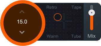
Drive
Adjust to control the amount of excitation applied to the signal.
X/Y Pad
Blends different harmonic profiles to achieve the sound you want to hear. By moving the node on the pad, you can get a mix of the four profiles as described in the table below.
| Profiles | Description |
|---|---|
| RETRO | Edgy, biting, transistor-based fuzz with a slow decay of odd harmonics. |
| TAPE | Bright, emphasis on odd harmonics without adding damaging artifacts. |
| TUBE | Clear tonal excitation with emphasis on dynamics and transient attacks with a less harsh result than Tape or Retro. |
| WARM | Similar to Tube, but with quickly decaying even harmonics that add color and character. |
Mix
Adjusts how much of the wet (processed) signal is applied to the dry (unprocessed) signal. The processing on the signal is dictated by the X/Y pad settings. Using the mix slider for a different blend of signals can have varying results:
- For a more extreme effect: set the blend to the maximum amount.
- For less distinct and more integrated effect: set the blend to the middle of the slider or lower.
Sculptor
Overview
Sculptor is a spectral shaping tool that brings clarity and polish to your audio tracks. This means removing muddiness, reducing harshness, and helping shape your tracks into better versions of themselves. Spectral shaping is multiband compression taken to the extreme. Instead of compressing 4 frequency bands, spectral shaping compresses the signal in up to 32 frequency bands, allowing for a control that is more tailored for the signal. Compression thresholds can be set toward a desired spectral shape or remain adaptively adjustable to compress the signal “toward itself”, i.e. its own time-averaged spectral shape.
Sculptor will apply dynamics processing to areas within the frequency spectrum based on a threshold aimed at hitting the selected Target Curve. The target curves are the idealized spectral version of the selected instrument. When using this with multiple instrument tracks, this results in greater instrumental separation.
NOTE: Sculptor is Not Meant To Introduce Distortion
Sculptor is designed specifically to not add any distortion, preserving the integrity of the original signal as transparently as possible.
Upon opening Sculptor, or after pressing the Reset button, you will be prompted to select a target curve. Choose a target curve that best reflects the instrument you are working on to load it.
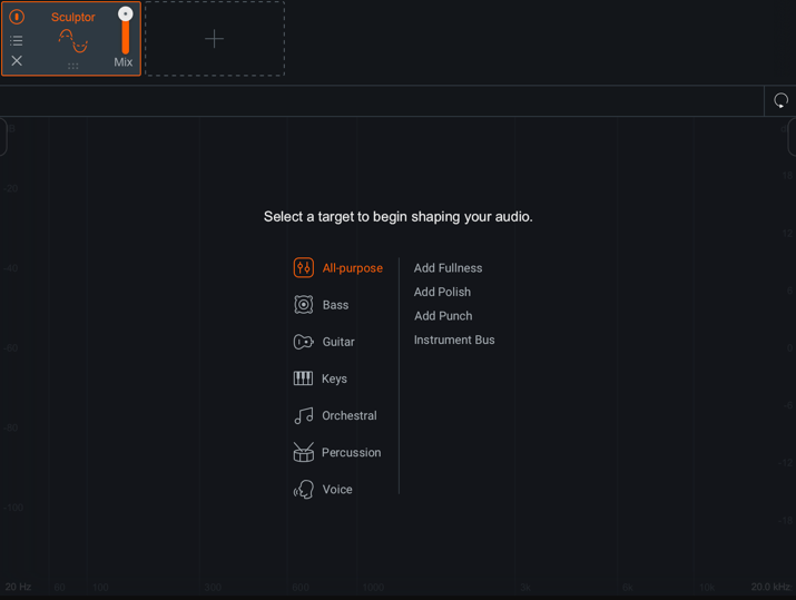
After selecting a target curve, you will be able to interact with the Sculptor module controls.
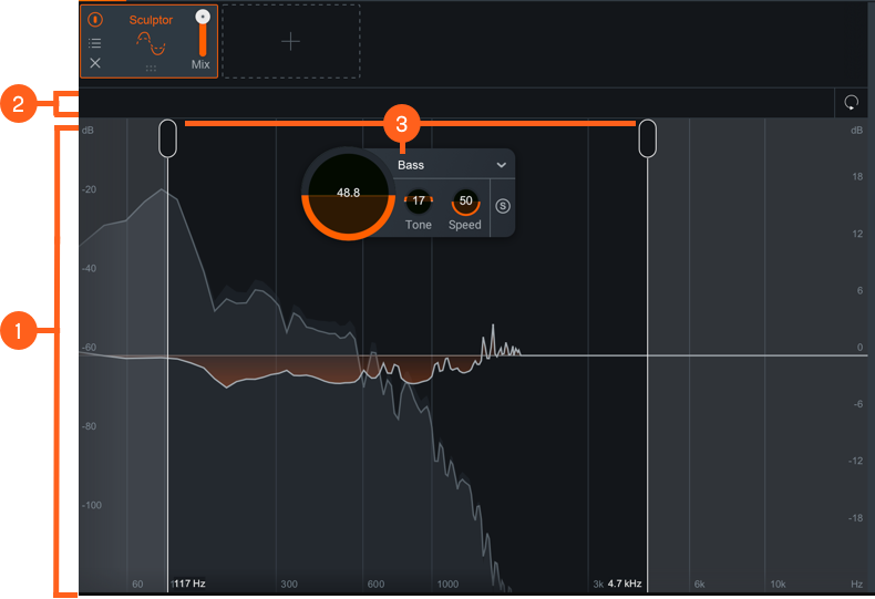
The Sculptor module includes the following sections:
Meters and Displays
The following meters and displays are included in the Sculptor module:
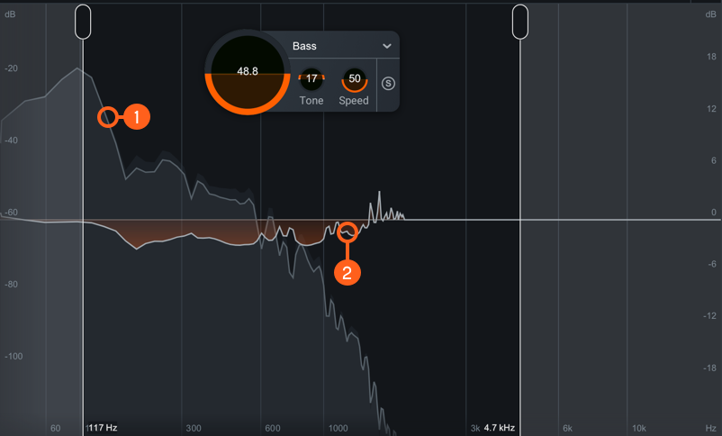
- Spectrum Displays
- Spectrum Analyzer: displays the magnitude (amplitude vs dB) of the input and output signals across the frequency spectrum in real-time
- Input signal spectrum: displays the dry (unprocessed) signal as a dark grey spectrum behind the output signal.
- Output signal spectrum: displays the wet (processed) signal as a light grey spectrum, in front of the input signal.
- Difference Meter: Displays the amount of gain that is being added or removed by dynamics processing in order to match the selected frequency range to the target curve.
Module Header
The following controls are included in the module header area of the Sculptor module:

- LFE: This option appears when Neutron is inserted on a 5.1 or 7.1 surround track. When enabled, the LFE channel will be processed along with all other channels. When disabled, the LFE channel will not be processed by the associated module. If necessary, latency compensation is applied to the LFE channel when it is disabled, to ensure timing is maintained between all channels.
- Reset: Returns all controls in the Sculptor module to their factory default values. If you wish to return to settings you were using before clicking the Reset button, you can use the Undo History window to revert to the settings before the Reset event.
Controls
The Sculptor module includes the following controls:
Range Selectors
You can adjust the area of applied processing by moving the Range Selector handles.
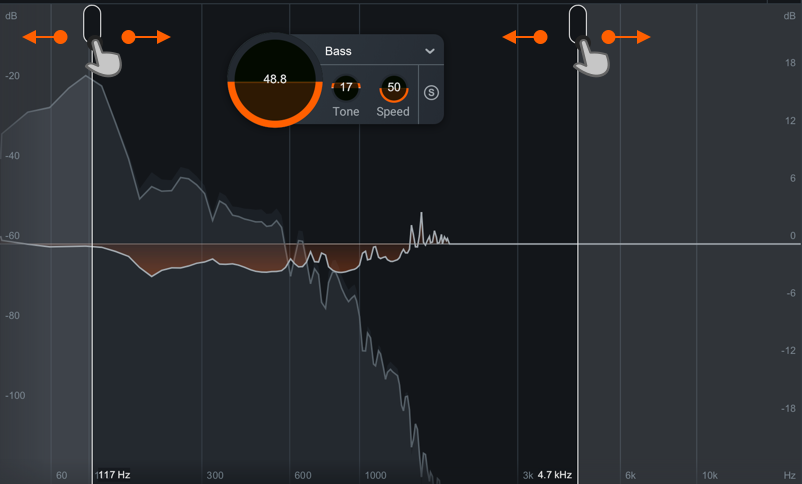
Move the Range Selectors left or right across the display.
- With a narrow range, you can surgically apply spectral shaping to areas with too much or too little energy by limiting processing to meet target curve on a specific range.
- With a wide range, you can address coloration similar to an EQ by applying processing on the whole spectrum to adjust overall balance.
HUD Controls
The controls in the Sculptor module work together to influence the shape, speed, and target of the spectral shaping applied to the input signal. The following controls are available in the Sculptor HUD:

- Amount: Adjusts the amount of processing applied to meet your selected target.
- Target Curve Menu: Determines the baseline target curve for Sculptor to apply to your track. We designed a variety of targets curves to specifically address different instrument types. Each target curve represents an idealized version of that instrument’s spectral characteristics.
- Tone: Adjusts the timbral characteristics of the signal.
- Speed: Adjusts the ballistics of the applied compression.
- Solo: Enable to hear processing on only the range selected.
Visual Mixer
Overview
The Visual Mixer is a controller that uses node-based mixing that connects you to compatible iZotope plug-ins in your session. In Visual Mixer, you can visually place your music in a virtual space. Using iZotope’s IPC technology, you can adjust the pan, volume, and stereo width of any Neutron 3 instance in your session. You can also access Mix Assistant from Visual Mixer.
NOTE: See Assistant Chapter for More Information
For more information on how to use Mix Assistant with Visual Mixer, please visit the Assistants chapter.
Plug-in Interface
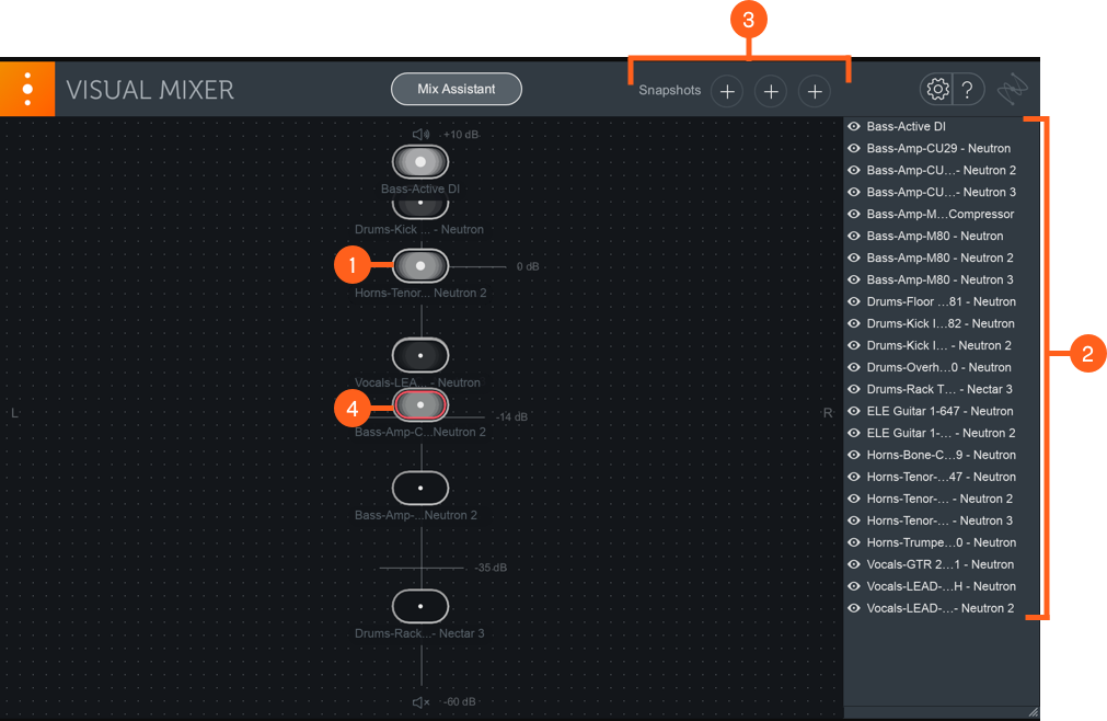
| Label | Section |
|---|---|
|
|
Plug-in Controls |
|
|
Plug-in List |
|
|
Mix Snapshots |
|
|
Activity Metering |
Plug-in Controls
X/Y Pad
Move nodes within the X/Y pad interface to control different elements of your mix remotely.
Panning
Adjust the stereo pan control of any Neutron 3 plug-in by dragging nodes left or right in the X/Y pad.
Volume
Adjust the output gain of any Neutron 3 plug-in in your session by dragging nodes up and down in the X/Y pad.
Width
Adjust the Width amount of any stereo Neutron 3 plug-in in your session by clicking on a node and adjusting the handles that appear on the left and right edges of the node.
NOTE: About Mono instances
Panning and Width can’t be adjusted from the Visual Mixer for mono instances of Neutron 3 plug-ins.
Plug-in List
The list on the right side of the Visual Mixer interface displays the names of all Neutron 3 plug-ins in your session.
Clicking on the eye button to the left of the instance name will hide or show that instance in the X/Y pad.

You can double-click on an instance name to rename it from the Visual Mixer.
Mix Snapshots
Save Mix Snapshots to compare different configurations or hide/show states for the nodes in the Visual Mixer.

Set
Save a snapshot by clicking on the “Set” button above the A/B/C buttons.
A/B/C
Toggles the view to display the Mix Snapshot you set for a given button. These are greyed out until a snapshot is set.
Activity Metering
Nodes display activity metering to indicate if audio is passing through the associated plug-in.
When red is displayed in the activity meter for a given node, it is indicating the associated Neutron 3 plug-in output is clipping.

Relay
Overview
Relay can send metering data to and receive information from select Inter Plug-in Communication (IPC) compatible iZotope plug-ins.
Want to Know More About Relay?
For more information about Relay, click on the “?” (Help) button in the Relay plug-in to access Relay’s Help Documentation.
Relay and Neutron Masking Meter
Relay can be selected as a source in the Masking Meter included in Neutron 3 (EQ module) and the Neutron 3 EQ component plug-in.
Relay and Visual Mixer
Relay controls can be remotely modified in the Neutron 3 Visual Mixer. Moving a Relay node up or down in the Visual Mixer will adjust the gain slider in the remote instance. Moving a Relay node left or right in the Visual Mixer will adjust the pan control in the remote instance (stereo Relay instances only). Dragging Relay node handles in the Visual mixer will adjust the width parameter in the remote instance (stereo Relay instances only).
Relay and Mix Assistant
With the new Mix Assistant feature, we recommend a workflow using Relay in your session. For more information on this workflow, see the Assistants chapter.
Relay and Tonal Balance Control
Relay can be selected as a source in the Tonal Balance Control plug-in.
Presets
Overview
You can choose from a wide variety of factory presets or save your own custom settings in the Neutron preset manager.
Global Presets
You can open the global preset manager by clicking the preset bar in the header area of any Neutron 3 plug-in.
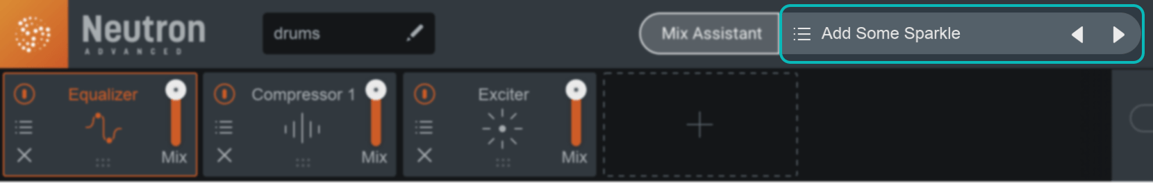
Tip
You can quickly cycle through presets in the list by clicking the left arrow (previous preset) or right arrow (next preset) buttons to the right of the preset button.
Module Presets
You can save and load settings in an individual Neutron 3 module using the module preset manager. You can click on the presets button in each module tile to open the corresponding module preset manager window.
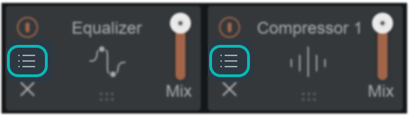
Factory and Custom Presets
The preset manager windows are divided into two tabs:
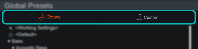
- iZotope: lists all factory presets installed with Neutron 3.
- Custom: lists all custom presets you have saved or modified in Neutron 3.
Default and Working Settings
There are two common options that are always available at the top of the preset list in the iZotope and Custom tabs:
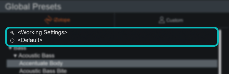
- Working Settings: Loads your most recent changes that are not otherwise associated with a preset.
- Default: Loads the factory default settings.
Dirty state indicator
When you make changes to a preset an asterisk (*) will be shown at the beginning of the preset name to indicate that it has been modified. You can add a new preset to save your settings or update the preset to dismiss the dirty state indicator.
Custom Preset Names and Comments
You can modify preset file/folder names and preset comments when the Custom tab is selected.
- Edit custom preset name: Double-click on a preset name to open an inline edit field. Press return to dismiss the inline edit field and save your changes.
- Edit custom preset comment: The area below the preset list displays descriptive text about the currently selected preset. Single-click the comment text box to open an inline edit field, press return to save changes to the comment.
Presets Window Footer
The following buttons are located in the footer of the Presets window:

- Deletes the currently selected custom preset or preset folder.
- Update: Saves changes to a modified custom preset. Note: Update is only available in the global preset manager, you cannot update module presets.
- Folder: Adds a new custom preset folder.
- New: Creates a new preset based on the current settings.
- Close: Dismiss the Presets window.
Organize Custom Presets
In the Custom tab, you can click and drag presets or folders over other folders in the list to move them into that folder.
Preset Locations
Factory presets are installed to the following locations:
- Windows:
C:\Program Files\iZotope\Neutron 3\Presets\ - Mac:
/Library/Application Support/iZotope/Neutron 3/Presets/
Custom presets are saved to the following default locations:
- Windows:
C:\Users\Username\Documents\iZotope\Neutron 3\Presets\ - Mac:
/Users/Username/Documents/iZotope/Neutron 3/Presets/
Override custom preset save locations
A ... button will appear in the upper left hand corner of the preset window when the Custom tab is
selected.
Click the button to open a system dialog and select a new directory to save your custom presets to.
The custom paths for global and per module presets are set individually in their respective preset windows.
Options
Overview
The Options window allows you to manage your authorization, check for updates, and adjust global and module processing controls. Click on the gear button in the upper right corner of the Neutron 3 interface to open the Options window.

There are three sections to the Options window.

| Label | Section | Controls and Features |
|---|---|---|
|
|
Options Tabs | Click on the tabs in the header of the options window to view access the different settings. |
|
|
Per-Tab Options | Displays the options available for each Options tab. |
|
|
Options Window Controls | You can save, cancel or reset all options to factory default states using the buttons in the footer area of the Options window.Question Mark: Access Help Documentation for Options.Ok: Saves any changes you have made to the options and closes the window.Cancel: Reverts changes to options and closes the window.Reset: Resets all Options to their factory default settings. |
General Options
The general options tab allows you to manage global processing modes, tooltips, authorization, and check for available updates to Neutron 3.
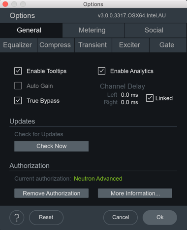
- Enable Tooltips: Select to enable tooltip displays when hovering your cursor over controls in Neutron 3.
- Auto Gain: Select to apply gain to the bypassed output signal in order to match the level of the processed output signal.
- True Bypass: Allows Neutron to disengage a module’s latency when that module is bypassed. This will
result in a click when enabling or disabling module bypass but avoids unnecessary latency compensation and
CPU usage.
True Bypass & Auto Gain
Auto Gain and True Bypass cannot be enabled at the same time. Enabling True Bypass will deselect and disable the Auto Gain option.
- Enable Analytics: Enables anonymous usage data to be sent to iZotope to help us improve our products.
- Channel Delay:
- Left & Right: Adjusts the left or right channel delay amount (in milliseconds).
- Link: Links left and right channel delay amount adjustments.
Updates
- Download Product Portal: To stay up to date with new versions, download the iZotope Product Portal application.
- Check for Updates: Manually check for available updates. Clicking this button will open the Product Portal application and check for updates.
- Download Update: If an update is available, a small yellow dot will appear. Clicking the Download Update button in the options window will launch the Product Portal application and display the Updates page.
Authorization
Displays your current authorization status.
- Authorize Neutron 3 by clicking on Authorize to open the authorization window.
- Deauthorize Neutron 3 by clicking on Remove Authorization to remove the authorization from your machine.
- Click More information to take you to the authorization help section of iZotope’s website.
Visit the Authorization section for more information.
Metering Options
You can alter the following options in the Metering Tab.
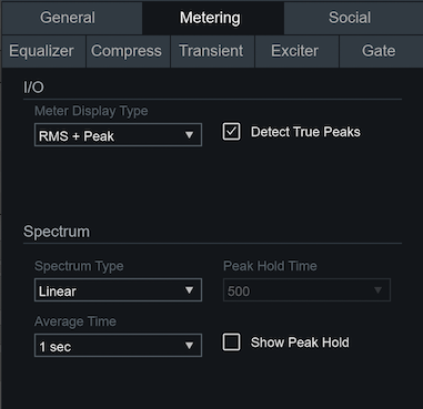
I/O
- METER DISPLAY TYPE: Determines the meter type displayed in the I/O meters.
- RMS + Peak: displays a lower bright bar representing the average level (RMS) and a higher dimmer bar representing peak level. There is also a moving line above the bar representing the most recent peak level or peak hold.
- Short Term + Peak: uses short-term loudness calculation to display a more perceptually accurate measurement than RMS. This measurement is useful in monitoring immediate trends of loudness in your audio.
- DETECT TRUE PEAKS: Select to accurately measure the signal that will result from digital to analog conversion. By default, the Input/Output meters will only indicate clipping which occurs within the digital domain.
Spectrum
- Spectrum Type: Determines the display type used by the spectrum analyzer meters. Options include:
- Linear: A continuous line connecting the calculated points of the spectrum.
- 1/3 Octave: Splits the spectrum into bars with a width of 1⁄3 of an octave. Although the spectrum is split into discrete bands, this option can provide excellent resolution at lower frequencies.
- Critical: Splits the spectrum into bands that correspond to how we hear, or more specifically how we differentiate between sounds of different frequencies. Each band represents sounds that are considered “similar” in frequency.
- Full Octave: Splits the spectrum into bars with a width of one full octave.
- Peak Hold Time: Determines how long spectrum peaks are displayed after they occur. Options include: 5 ms, 250 ms, 500 ms, 1,000 ms, 5,000 ms, and Infinite.
- Average Time: Adjusts the averaging time of the spectrum calculation. Higher average times can be useful for viewing the overall tonal balance of a mix, while shorter average times provide a more real-time display. Options include: Real Time, 1 sec, 3 sec, 5 sec, 10 sec, and Infinite.
- Show Peak Hold: Select to show the peak hold display in the spectrum meters.
Social Options
The Social tab contains links for you to explore iZotope’s social media platforms, such as Facebook, Twitter, and Instagram, and educational content platforms, such as our Youtube channel and our Tips & Tutorials for Neutron 3.
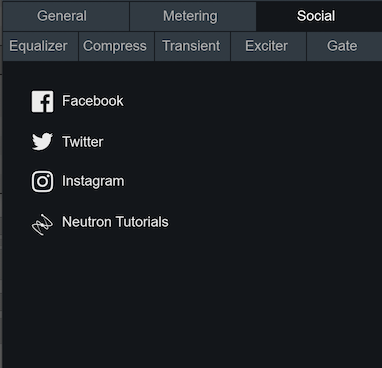
EQ Options
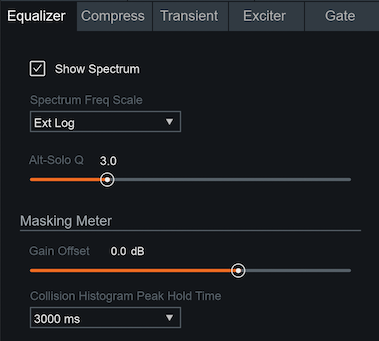
- SHOW SPECTRUM: Select to display a real-time spectrum analyzer signal underneath the Equalizer curve. This can be useful in showing the frequency balance of your mix and the changes occurring as you apply equalization.
- SPECTRUM FREQUENCY SCALE: Allows you to adjust the scale of the EQ frequency spectrum.
- ALT-SOLO Q: Determines the bandwidth (Q) of the Alt-Solo feature in the Equalizer module.
Masking Meter
- GAIN OFFSET: Adjusts the offset of the input level for the Masking Meter to match the fader level of your current track.
- COLLISION HISTOGRAM PEAK HOLD TIME: Choose the calculation window of peaks displayed in the
Masking Meter Histogram from the dropdown menu. The following options
are available:
- 400 ms: Calculates events across a very quickly moving window of 400 milliseconds.
- 3,000 ms: Most useful setting. Calculates events across a moving window of three seconds.
- Infinite: Useful if you want to see all masking that occurs over the entire duration of an audio segment from start to end.
Module Options
The Module Options refer to the Option tabs for the Compressor, Transient Shaper, Exciter, and Gate. The options for each of these modules are the same, but affect the individual module of that Options tab.
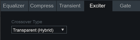
Crossovers
The Compress, Transient, Exciter and Gate tabs contain crossover options for multiband processing. The crossover options include:
- ZERO LATENCY (ANALOG): provides a natural analog character at the expense of some phase distortion.
- TRANSPARENT (HYBRID): provides an IIR (Infinite Impulse Response) analog crossover designed to reduce the phase and frequency distortion commonly found in other analog crossovers without sacrificing efficiency and warmth.
Glossary
Band
Short for “frequency band” which is a range or interval in the frequency spectrum often divided into low, mid or high-frequency bands.
Band shelf
Hybrid filter shape combining attributes of a shelving filter and a peaking filter.
Bandpass
A type of filter that passes frequencies between two cutoff frequencies and attenuates frequencies outside of the pass range. A band-reject filter operates inversely, attenuating frequencies within the cutoff range and passing frequencies outside of the range.
Bandwidth
Describes the range of frequencies being affected by a signal processor. Inversely proportional to Q.
Baxandall
A type of first order shelving equalizer typically found in the tone control of high fidelity home audio components.
Butterworth filter
A filter shape designed to have a flat frequency response in the passband.
Component Plug-in
The plug-in equivalent of a processing module included in the Neutron 3 mothership plug-in.
Crossover
A series of filters that separate the frequency spectrum into ranges.
Detection circuit
The component that evaluates signal amplitude to trigger a processor.
Envelope
The varying amplitude of sound over time. This can be broken into four stages: attack, decay, sustain, and release.
FFT (Fast Fourier Transform)
A procedure for the calculation of a signal frequency spectrum. The greater the FFT size, the greater the frequency resolution, i.e., notes and tonal events will be clearer at larger sizes.
Filter
Audio filters are frequency dependent amplifier circuits that boost (amplify), cut (attenuate), or pass ranges of the audible frequency spectrum.
Inter Plug-in Communication (IPC)
Inter Plug-in Communication is a feature which enables compatible iZotope plug-ins to send and receive metering data or control adjustments from other compatible iZotope plug-in within a session.
HUD (Heads-Up Display)
A panel through which you can access module controls.
Hysteresis
Describes a system or process whose response depends on its current state as well as its history.
LFE (Low-Frequency Effects)
A band-limited audio channel dedicated to low frequency content (< 120Hz). The LFE channel is sent to a speaker called a subwoofer that is designed to reproduce low frequency content.
Limiter
A high ratio dynamic range controller used to prevent overmodulation.
Masking
In the case of two or more signals that share overlapping frequency content, the higher amplitude signal causes the lower amplitude signal to appear quieter.
Mothership
A term used to describe the main Neutron plug-in. The mothership includes all of the Neutron processing modules in a single plug-in.
Multiband
More than one band across a spectrum.
Pre-Emphasis
An emphasis in a frequency band before the saturation is applied to emphasize the effect in that band.
Q
In an equalizer, it is the center frequency divided by bandwidth.
Resonant Filter
Has a complex nature of adjustment such that at the cut off point you can increase or attenuate the resonance. Typically is accompanied by significant phase shift or ringing.
Saturation
A harmonic type of non-linear distortion.
Sidechain
The signal that feeds the detection circuit in a processor.
Short Term Loudness
Loudness measurement calculated over the course of 3 seconds. Short-term measurements are useful for monitoring immediate trends in loudness.
Spectral Shaping
Spectral Shaping can be described as real-time, dynamic adjustment of the frequency spectrum, falling somewhere between dynamic equalization and multiband compression.
Spectrum Analyzer
A Spectrum Analyzer is a meter that measures amplitude across the frequencies which encompass the spectrum of human hearing. The vertical axis represents amplitude while the horizontal axis represents frequency.
Waveform
A visual representation of the envelope of the soundwave. (amplitude representation).
Customer Care
Purchasing Neutron 3
If you are using the demo version of Neutron 3 and would like the full version, you can purchase Neutron 3 direct from the iZotope online store: izotope.com/store
Once your purchase is complete, you will be sent an email confirmation and a full version serial number that can be used to fully authorize your current installation of Neutron 3.
iZotope Customer Care policy
iZotope is happy to provide professional technical Customer Care to all registered users absolutely free of charge. support.izotope.com
We also offer valuable pre-sales technical Customer Care to customers who may be interested in purchasing an iZotope product. Before contacting iZotope, you can search our Product Knowledgebase to see if the solution to your problem has already been published.
How long does iZotope provide customer support for purchased products?
You can email us with any question for 12 months after you buy any iZotope product. Past 12 months, we’ll still help you with your account and authorization but will not provide technical support for in-depth product questions. If you need more detailed help on how to use the product, please check out our FAQs and Tutorials.
How long does iZotope support its products?
Although we can’t guarantee it, we do our best to keep our products up to date with the operating systems and plug-in hosts that we support. Sometimes, other companies make changes that we’re not able to support, but we actively work with other companies to avoid these sorts of compatibility problems. We also do our best to address bug fixes within the product itself to ensure our products operate in accordance with our specifications.
We will provide software updates for 12 months from product release. After 12 months, no software updates will be provided.
For details on what operating systems and plug-in host software are officially supported for a product, please check that product’s Specs page.
Contacting iZotope Customer Care
For additional help with Neutron 3:
- Check out the Customer Care pages on our website at support.izotope.com
- Contact our Customer Care department at support@izotope.com
iZotope’s highly trained Customer Care team is committed to responding to all requests within one (1) business day and frequently respond faster. Please try to explain your problem with as much detail and clarity as possible. This will ensure our ability to solve your problem accurately, the first time around. Please include all system specs and the build/version of Neutron 3 that you are using.
Once your Customer Care request is submitted, you will receive a confirmation email from iZotope Customer Care. If you do not receive this email within a few minutes, please check your spam folder and make sure our responses are not getting blocked. To prevent this from happening please add support@izotope.com to your list of allowed email addresses.
International Distribution
Customer Care is also available from our international distributors worldwide for any customers who purchased their iZotope products through a certified iZotope distributor.
Check with your local distributor for availability. If you would like help locating your local distributor please contact iZotope Customer Care.
Thanks for using Neutron 3!
-The iZotope Team
License Information
Table of Contents
- Anti-Grain Geometry
- Better Enums
- Box2D
- Bravura
- C++ Rest SDK
- Eigen
- FreeType
- GLEW
- gsl
- IcoMoon
- Intel® Integrated Performance Primitives (Intel® IPP)
- JsonCpp
- LibXML2
- Material Docs Theme
- nanomsg
- Netlib numeralgo na10 Aberth’s method
- readerwriterqueue
- Roboto font family
- Skia
- TinyXML
- Tipue Search
- vectorize
- xsimd
- Yoga
- zlib
Anti-Grain Geometry
Version 2.4
Copyright (c) 2002-2005 Maxim Shemanarev (McSeem).
Redistribution and use in source and binary forms, with or without modification, are permitted provided that the following conditions are met:
-
Redistributions of source code must retain the above copyright notice, this list of conditions and the following disclaimer.
-
Redistributions in binary form must reproduce the above copyright notice, this list of conditions and the following disclaimer in the documentation and/or other materials provided with the distribution.
-
The name of the author may not be used to endorse or promote products derived from this software without specific prior written permission.
THIS SOFTWARE IS PROVIDED BY THE AUTHOR ‘‘AS IS’’ AND ANY EXPRESS OR IMPLIED WARRANTIES, INCLUDING, BUT NOT LIMITED TO, THE IMPLIED WARRANTIES OF MERCHANTABILITY AND FITNESS FOR A PARTICULAR PURPOSE ARE DISCLAIMED. IN NO EVENT SHALL THE AUTHOR BE LIABLE FOR ANY DIRECT, INDIRECT, INCIDENTAL, SPECIAL, EXEMPLARY, OR CONSEQUENTIAL DAMAGES (INCLUDING, BUT NOT LIMITED TO, PROCUREMENT OF SUBSTITUTE GOODS OR SERVICES; LOSS OF USE, DATA, OR PROFITS; OR BUSINESS INTERRUPTION) HOWEVER CAUSED AND ON ANY THEORY OF LIABILITY, WHETHER IN CONTRACT, STRICT LIABILITY, OR TORT (INCLUDING NEGLIGENCE OR OTHERWISE) ARISING IN ANY WAY OUT OF THE USE OF THIS SOFTWARE, EVEN IF ADVISED OF THE POSSIBILITY OF SUCH DAMAGE.
Better Enums
Version 0.11.1
Copyright (c) 2012-2016, Anton Bachin. All rights reserved.
Redistribution and use in source and binary forms, with or without modification, are permitted provided that the following conditions are met:
-
Redistributions of source code must retain the above copyright notice, this list of conditions and the following disclaimer.
-
Redistributions in binary form must reproduce the above copyright notice, this list of conditions and the following disclaimer in the documentation and/or other materials provided with the distribution.
THIS SOFTWARE IS PROVIDED BY THE COPYRIGHT HOLDERS AND CONTRIBUTORS “AS IS” AND ANY EXPRESS OR IMPLIED WARRANTIES, INCLUDING, BUT NOT LIMITED TO, THE IMPLIED WARRANTIES OF MERCHANTABILITY AND FITNESS FOR A PARTICULAR PURPOSE ARE DISCLAIMED. IN NO EVENT SHALL THE COPYRIGHT HOLDER OR CONTRIBUTORS BE LIABLE FOR ANY DIRECT, INDIRECT, INCIDENTAL, SPECIAL, EXEMPLARY, OR CONSEQUENTIAL DAMAGES (INCLUDING, BUT NOT LIMITED TO, PROCUREMENT OF SUBSTITUTE GOODS OR SERVICES; LOSS OF USE, DATA, OR PROFITS; OR BUSINESS INTERRUPTION) HOWEVER CAUSED AND ON ANY THEORY OF LIABILITY, WHETHER IN CONTRACT, STRICT LIABILITY, OR TORT (INCLUDING NEGLIGENCE OR OTHERWISE) ARISING IN ANY WAY OUT OF THE USE OF THIS SOFTWARE, EVEN IF ADVISED OF THE POSSIBILITY OF SUCH DAMAGE.
Box2D
Copyright (c) 2006-2017 Erin Catto.
This software is provided ‘as-is’, without any express or implied warranty. In no event will the authors be held liable for any damages arising from the use of this software.
Permission is granted to anyone to use this software for any purpose, including commercial applications, and to alter it and redistribute it freely, subject to the following restrictions:
-
The origin of this software must not be misrepresented; you must not claim that you wrote the original software. If you use this software in a product, an acknowledgment in the product documentation would be appreciated but is not required.
-
Altered source versions must be plainly marked as such, and must not be misrepresented as being the original software.
-
This notice may not be removed or altered from any source distribution.
Bravura
Copyright © 2015, Steinberg Media Technologies GmbH http://www.steinberg.net/, with Reserved Font Name “Bravura”.
This Font Software is licensed under the SIL Open Font License, Version 1.1. This license is copied below, and is also available with a FAQ at: http://scripts.sil.org/OFL
SIL OPEN FONT LICENSE Version 1.1 - 26 February 2007
PREAMBLE
The goals of the Open Font License (OFL) are to stimulate worldwide development of collaborative font
projects, to support the font creation efforts of academic and linguistic communities, and to provide a free
and open framework in which fonts may be shared and improved in partnership with others.
The OFL allows the licensed fonts to be used, studied, modified and redistributed freely as long as they are not sold by themselves. The fonts, including any derivative works, can be bundled, embedded, redistributed and/or sold with any software provided that any reserved names are not used by derivative works. The fonts and derivatives, however, cannot be released under any other type of license. The requirement for fonts to remain under this license does not apply to any document created using the fonts or their derivatives.
DEFINITIONS
“Font Software” refers to the set of files released by the Copyright Holder(s) under this license and clearly
marked as such. This may include source files, build scripts and documentation.
“Reserved Font Name” refers to any names specified as such after the copyright statement(s).
“Original Version” refers to the collection of Font Software components as distributed by the Copyright Holder(s).
“Modified Version” refers to any derivative made by adding to, deleting, or substituting – in part or in whole – any of the components of the Original Version, by changing formats or by porting the Font Software to a new environment.
“Author” refers to any designer, engineer, programmer, technical writer or other person who contributed to the Font Software.
PERMISSION & CONDITIONS
Permission is hereby granted, free of charge, to any person obtaining a copy of the Font Software, to use,
study, copy, merge, embed, modify, redistribute, and sell modified and unmodified copies of the Font Software,
subject to the following conditions:
-
Neither the Font Software nor any of its individual components, in Original or Modified Versions, may be sold by itself.
-
Original or Modified Versions of the Font Software may be bundled, redistributed and/or sold with any software, provided that each copy contains the above copyright notice and this license. These can be included either as stand-alone text files, human-readable headers or in the appropriate machine-readable metadata fields within text or binary files as long as those fields can be easily viewed by the user.
-
No Modified Version of the Font Software may use the Reserved Font Name(s) unless explicit written permission is granted by the corresponding Copyright Holder. This restriction only applies to the primary font name as presented to the users.
-
The name(s) of the Copyright Holder(s) or the Author(s) of the Font Software shall not be used to promote, endorse or advertise any Modified Version, except to acknowledge the contribution(s) of the Copyright Holder(s) and the Author(s) or with their explicit written permission.
-
The Font Software, modified or unmodified, in part or in whole, must be distributed entirely under this license, and must not be distributed under any other license. The requirement for fonts to remain under this license does not apply to any document created using the Font Software.
TERMINATION
This license becomes null and void if any of the above conditions are not met.
DISCLAIMER
THE FONT SOFTWARE IS PROVIDED “AS IS”, WITHOUT WARRANTY OF ANY KIND, EXPRESS OR IMPLIED, INCLUDING BUT NOT
LIMITED TO ANY WARRANTIES OF MERCHANTABILITY, FITNESS FOR A PARTICULAR PURPOSE AND NONINFRINGEMENT OF
COPYRIGHT, PATENT, TRADEMARK, OR OTHER RIGHT. IN NO EVENT SHALL THE COPYRIGHT HOLDER BE LIABLE FOR ANY CLAIM,
DAMAGES OR OTHER LIABILITY, INCLUDING ANY GENERAL, SPECIAL, INDIRECT, INCIDENTAL, OR CONSEQUENTIAL DAMAGES,
WHETHER IN AN ACTION OF CONTRACT, TORT OR OTHERWISE, ARISING FROM, OUT OF THE USE OR INABILITY TO USE THE FONT
SOFTWARE OR FROM OTHER DEALINGS IN THE FONT SOFTWARE.
C++ Rest SDK
Version 2.10.15
Main Library:
Copyright (c) 2014, Peter Thorson. All rights reserved.
Redistribution and use in source and binary forms, with or without modification, are permitted provided that the following conditions are met:
-
Redistributions of source code must retain the above copyright notice, this list of conditions and the following disclaimer.
-
Redistributions in binary form must reproduce the above copyright notice, this list of conditions and the following disclaimer in the documentation and/or other materials provided with the distribution.
-
Neither the name of the WebSocket++ Project nor the names of its contributors may be used to endorse or promote products derived from this software without specific prior written permission.
THIS SOFTWARE IS PROVIDED BY THE COPYRIGHT HOLDERS AND CONTRIBUTORS “AS IS” AND ANY EXPRESS OR IMPLIED WARRANTIES, INCLUDING, BUT NOT LIMITED TO, THE IMPLIED WARRANTIES OF MERCHANTABILITY AND FITNESS FOR A PARTICULAR PURPOSE ARE DISCLAIMED. IN NO EVENT SHALL PETER THORSON BE LIABLE FOR ANY DIRECT, INDIRECT, INCIDENTAL, SPECIAL, EXEMPLARY, OR CONSEQUENTIAL DAMAGES (INCLUDING, BUT NOT LIMITED TO, PROCUREMENT OF SUBSTITUTE GOODS OR SERVICES; LOSS OF USE, DATA, OR PROFITS; OR BUSINESS INTERRUPTION) HOWEVER CAUSED AND ON ANY THEORY OF LIABILITY, WHETHER IN CONTRACT, STRICT LIABILITY, OR TORT (INCLUDING NEGLIGENCE OR OTHERWISE) ARISING IN ANY WAY OUT OF THE USE OF THIS SOFTWARE, EVEN IF ADVISED OF THE POSSIBILITY OF SUCH DAMAGE.
Bundled Libraries:
****** Base 64 Library (base64/base64.hpp) ******
base64.hpp is a repackaging of the base64.cpp and base64.h files into a single header suitable for use as a
header only library. This conversion was done by Peter Thorson (webmaster@zaphoyd.com) in 2012. All
modifications to the code are redistributed under the same license as the original, which is listed below.
base64.cpp and base64.h
Copyright (C) 2004-2008 René Nyffenegger
This source code is provided ‘as-is’, without any express or implied warranty. In no event will the author be held liable for any damages arising from the use of this software.
Permission is granted to anyone to use this software for any purpose, including commercial applications, and to alter it and redistribute it freely, subject to the following restrictions:
-
The origin of this source code must not be misrepresented; you must not claim that you wrote the original source code. If you use this source code in a product, an acknowledgment in the product documentation would be appreciated but is not required.
-
Altered source versions must be plainly marked as such, and must not be misrepresented as being the original source code.
-
This notice may not be removed or altered from any source distribution.
René Nyffenegger rene.nyffenegger@adp-gmbh.ch
****** SHA1 Library (sha1/sha1.hpp) ******
sha1.hpp is a repackaging of the sha1.cpp and sha1.h files from the shallsha1 library (http://code.google.com/p/smallsha1/) into a single header suitable for use as a header only library. This conversion was done by Peter Thorson (webmaster@zaphoyd.com) in 2013. All modifications to the code are redistributed under the same license as the original, which is listed below.
Copyright (c) 2011, Micael Hildenborg
All rights reserved.
Redistribution and use in source and binary forms, with or without modification, are permitted provided that the following conditions are met:
- Redistributions of source code must retain the above copyright notice, this list of conditions and the following disclaimer.
- Redistributions in binary form must reproduce the above copyright notice, this list of conditions and the following disclaimer in the documentation and/or other materials provided with the distribution.
- Neither the name of Micael Hildenborg nor the names of its contributors may be used to endorse or promote products derived from this software without specific prior written permission.
THIS SOFTWARE IS PROVIDED BY Micael Hildenborg ‘‘AS IS’’ AND ANY EXPRESS OR IMPLIED WARRANTIES, INCLUDING, BUT NOT LIMITED TO, THE IMPLIED WARRANTIES OF MERCHANTABILITY AND FITNESS FOR A PARTICULAR PURPOSE ARE DISCLAIMED. IN NO EVENT SHALL Micael Hildenborg BE LIABLE FOR ANY DIRECT, INDIRECT, INCIDENTAL, SPECIAL, EXEMPLARY, OR CONSEQUENTIAL DAMAGES (INCLUDING, BUT NOT LIMITED TO, PROCUREMENT OF SUBSTITUTE GOODS OR SERVICES; LOSS OF USE, DATA, OR PROFITS; OR BUSINESS INTERRUPTION) HOWEVER CAUSED AND ON ANY THEORY OF LIABILITY, WHETHER IN CONTRACT, STRICT LIABILITY, OR TORT (INCLUDING NEGLIGENCE OR OTHERWISE) ARISING IN ANY WAY OUT OF THE USE OF THIS SOFTWARE, EVEN IF ADVISED OF THE POSSIBILITY OF SUCH DAMAGE.
****** MD5 Library (common/md5.hpp) ******
md5.hpp is a reformulation of the md5.h and md5.c code from
http://www.opensource.apple.com/source/cups/cups-59/cups/md5.c to allow it to function as a component of a
header only library. This conversion was done by Peter Thorson (webmaster@zaphoyd.com) in 2012 for the
WebSocket++ project. The changes are released under the same license as the original (listed below)
Copyright (C) 1999, 2002 Aladdin Enterprises. All rights reserved.
This software is provided ‘as-is’, without any express or implied warranty. In no event will the authors be held liable for any damages arising from the use of this software.
Permission is granted to anyone to use this software for any purpose, including commercial applications, and to alter it and redistribute it freely, subject to the following restrictions:
- The origin of this software must not be misrepresented; you must not claim that you wrote the original software. If you use this software in a product, an acknowledgment in the product documentation would be appreciated but is not required.
- Altered source versions must be plainly marked as such, and must not be misrepresented as being the original software.
- This notice may not be removed or altered from any source distribution.
L. Peter Deutsch
ghost@aladdin.com
****** UTF8 Validation logic (utf8_validation.hpp) ******
utf8_validation.hpp is adapted from code originally written by Bjoern Hoehrmann bjoern@hoehrmann.de. See
http://bjoern.hoehrmann.de/utf-8/decoder/dfa/ for details.
The original license:
Copyright (c) 2008-2009 Bjoern Hoehrmann bjoern@hoehrmann.de
Permission is hereby granted, free of charge, to any person obtaining a copy of this software and associated documentation files (the “Software”), to deal in the Software without restriction, including without limitation the rights to use, copy, modify, merge, publish, distribute, sublicense, and/or sell copies of the Software, and to permit persons to whom the Software is furnished to do so, subject to the following conditions:
The above copyright notice and this permission notice shall be included in all copies or substantial portions of the Software.
THE SOFTWARE IS PROVIDED “AS IS”, WITHOUT WARRANTY OF ANY KIND, EXPRESS OR IMPLIED, INCLUDING BUT NOT LIMITED TO THE WARRANTIES OF MERCHANTABILITY, FITNESS FOR A PARTICULAR PURPOSE AND NONINFRINGEMENT. IN NO EVENT SHALL THE AUTHORS OR COPYRIGHT HOLDERS BE LIABLE FOR ANY CLAIM, DAMAGES OR OTHER LIABILITY, WHETHER IN AN ACTION OF CONTRACT, TORT OR OTHERWISE, ARISING FROM, OUT OF OR IN CONNECTION WITH THE SOFTWARE OR THE USE OR OTHER DEALINGS IN THE SOFTWARE.
Eigen
Version 3.4.99
Distributed under the Mozilla Public License v2.0 (MPLv2.0).
Full text of the license is available here: https://www.mozilla.org/en-US/MPL/2.0/
To receive a copy of the source code for the Eigen library distributed with this product under the under the terms of the MPLv2.0 please contact dev-support@izotope.com.
FreeType
Version 2.4.6
Portions of this software are copyright © 2011 The FreeType Project (www.freetype.org). All rights reserved.
GLEW
The OpenGL Extension Wrangler Library
Copyright (C) 2002-2008, Milan Ikits <milan ikits[]ieee org>
Copyright (C) 2002-2008, Marcelo E. Magallon <mmagallo[]debian org>
Copyright (C) 2002, Lev Povalahev
All rights reserved.
Redistribution and use in source and binary forms, with or without modification, are permitted provided that the following conditions are met:
-
Redistributions of source code must retain the above copyright notice, this list of conditions and the following disclaimer.
-
Redistributions in binary form must reproduce the above copyright notice, this list of conditions and the following disclaimer in the documentation and/or other materials provided with the distribution.
-
The name of the author may be used to endorse or promote products derived from this software without specific prior written permission.
THIS SOFTWARE IS PROVIDED BY THE COPYRIGHT HOLDERS AND CONTRIBUTORS “AS IS” AND ANY EXPRESS OR IMPLIED WARRANTIES, INCLUDING, BUT NOT LIMITED TO, THE IMPLIED WARRANTIES OF MERCHANTABILITY AND FITNESS FOR A PARTICULAR PURPOSE ARE DISCLAIMED. IN NO EVENT SHALL THE COPYRIGHT OWNER OR CONTRIBUTORS BE LIABLE FOR ANY DIRECT, INDIRECT, INCIDENTAL, SPECIAL, EXEMPLARY, OR CONSEQUENTIAL DAMAGES (INCLUDING, BUT NOT LIMITED TO, PROCUREMENT OF SUBSTITUTE GOODS OR SERVICES; LOSS OF USE, DATA, OR PROFITS; OR BUSINESS INTERRUPTION) HOWEVER CAUSED AND ON ANY THEORY OF LIABILITY, WHETHER IN CONTRACT, STRICT LIABILITY, OR TORT (INCLUDING NEGLIGENCE OR OTHERWISE) ARISING IN ANY WAY OUT OF THE USE OF THIS SOFTWARE, EVEN IF ADVISED OF THE POSSIBILITY OF SUCH DAMAGE.
Mesa 3-D graphics library Version: 7.0
Copyright (C) 1999-2007 Brian Paul All Rights Reserved.
Permission is hereby granted, free of charge, to any person obtaining a copy of this software and associated documentation files (the “Software”), to deal in the Software without restriction, including without limitation the rights to use, copy, modify, merge, publish, distribute, sublicense, and/or sell copies of the Software, and to permit persons to whom the Software is furnished to do so, subject to the following conditions:
The above copyright notice and this permission notice shall be included in all copies or substantial portions of the Software.
THE SOFTWARE IS PROVIDED “AS IS”, WITHOUT WARRANTY OF ANY KIND, EXPRESS OR IMPLIED, INCLUDING BUT NOT LIMITED TO THE WARRANTIES OF MERCHANTABILITY, FITNESS FOR A PARTICULAR PURPOSE AND NONINFRINGEMENT. IN NO EVENT SHALL BRIAN PAUL BE LIABLE FOR ANY CLAIM, DAMAGES OR OTHER LIABILITY, WHETHER IN AN ACTION OF CONTRACT, TORT OR OTHERWISE, ARISING FROM, OUT OF OR IN CONNECTION WITH THE SOFTWARE OR THE USE OR OTHER DEALINGS IN THE SOFTWARE.
Copyright (c) 2007 The Khronos Group Inc.
Permission is hereby granted, free of charge, to any person obtaining a copy of this software and/or associated documentation files (the “Materials”), to deal in the Materials without restriction, including without limitation the rights to use, copy, modify, merge, publish, distribute, sublicense, and/or sell copies of the Materials, and to permit persons to whom the Materials are furnished to do so, subject to the following conditions:
The above copyright notice and this permission notice shall be included in all copies or substantial portions of the Materials.
THE MATERIALS ARE PROVIDED “AS IS”, WITHOUT WARRANTY OF ANY KIND, EXPRESS OR IMPLIED, INCLUDING BUT NOT LIMITED TO THE WARRANTIES OF MERCHANTABILITY, FITNESS FOR A PARTICULAR PURPOSE AND NONINFRINGEMENT. IN NO EVENT SHALL THE AUTHORS OR COPYRIGHT HOLDERS BE LIABLE FOR ANY CLAIM, DAMAGES OR OTHER LIABILITY, WHETHER IN AN ACTION OF CONTRACT, TORT OR OTHERWISE, ARISING FROM, OUT OF OR IN CONNECTION WITH THE MATERIALS OR THE USE OR OTHER DEALINGS IN THE MATERIALS.
gsl
Copyright (c) 2015 Microsoft Corporation. All rights reserved.
This code is licensed under the MIT License (MIT).
Permission is hereby granted, free of charge, to any person obtaining a copy of this software and associated documentation files (the “Software”), to deal in the Software without restriction, including without limitation the rights to use, copy, modify, merge, publish, distribute, sublicense, and/or sell copies of the Software, and to permit persons to whom the Software is furnished to do so, subject to the following conditions:
The above copyright notice and this permission notice shall be included in all copies or substantial portions of the Software.
THE SOFTWARE IS PROVIDED “AS IS”, WITHOUT WARRANTY OF ANY KIND, EXPRESS OR IMPLIED, INCLUDING BUT NOT LIMITED TO THE WARRANTIES OF MERCHANTABILITY, FITNESS FOR A PARTICULAR PURPOSE AND NONINFRINGEMENT. IN NO EVENT SHALL THE AUTHORS OR COPYRIGHT HOLDERS BE LIABLE FOR ANY CLAIM, DAMAGES OR OTHER LIABILITY, WHETHER IN AN ACTION OF CONTRACT, TORT OR OTHERWISE, ARISING FROM, OUT OF OR IN CONNECTION WITH THE SOFTWARE OR THE USE OR OTHER DEALINGS IN THE SOFTWARE.
IcoMoon
IcoMoon-Free licensed under: CC BY 4.0
Intel® Integrated Performance Primitives (Intel® IPP)
Version 2019.0.5
LIMITATION OF LIABILITY. IN NO EVENT WILL INTEL BE LIABLE FOR ANY DIRECT, INDIRECT, INCIDENTAL, SPECIAL, EXEMPLARY, OR CONSEQUENTIAL DAMAGES (INCLUDING, BUT NOT LIMITED TO, PROCUREMENT OF SUBSTITUTE GOODS OR SERVICES; LOSS OF USE, DATA, OR PROFITS; OR BUSINESS INTERRUPTION) HOWEVER CAUSED AND ON ANY THEORY OF LIABILITY, WHETHER IN CONTRACT, STRICT LIABILITY, OR TORT (INCLUDING NEGLIGENCE OR OTHERWISE) ARISING IN ANY WAY OUT OF THE USE OF THIS SOFTWARE, EVEN IF ADVISED OF THE POSSIBILITY OF SUCH DAMAGE. YOU AGREE TO INDEMNIFY AND HOLD INTEL HARMLESS AGAINST ANY CLAIMS AND EXPENSES RESULTING FROM YOUR USE OR UNAUTHORIZED USE OF THE SOFTWARE.
No support. Intel may make changes to the Software, at any time without notice, and is not obligated to support, update or provide training for the Software.
Termination. Intel may terminate your right to use the Software in the event of your breach of this Agreement and you fail to cure the breach within a reasonable period of time.
Feedback. Should you provide Intel with comments, modifications, corrections, enhancements or other input (“Feedback”) related to the Software Intel will be free to use, disclose, reproduce, license or otherwise distribute or exploit the Feedback in its sole discretion without any obligations or restrictions of any kind, including without limitation, intellectual property rights or licensing obligations.
Compliance with laws. You agree to comply with all relevant laws and regulations governing your use, transfer, import or export (or prohibition thereof) of the Software.
Governing law. All disputes will be governed by the laws of the United States of America and the State of Delaware without reference to conflict of law principles and subject to the exclusive jurisdiction of the state or federal courts sitting in the State of Delaware, and each party agrees that it submits to the personal jurisdiction and venue of those courts and waives any objections. The United Nations Convention on Contracts for the International Sale of Goods (1980) is specifically excluded and will not apply to the Software.
Other names and brands may be claimed as the property of others.
JsonCpp
Version 1.2.1
Copyright (c) 2007-2010 Baptiste Lepilleur and The JsonCpp Authors
Permission is hereby granted, free of charge, to any person obtaining a copy of this software and associated documentation files (the “Software”), to deal in the Software without restriction, including without limitation the rights to use, copy, modify, merge, publish, distribute, sublicense, and/or sell copies of the Software, and to permit persons to whom the Software is furnished to do so, subject to the following conditions:
The above copyright notice and this permission notice shall be included in all copies or substantial portions of the Software.
THE SOFTWARE IS PROVIDED “AS IS”, WITHOUT WARRANTY OF ANY KIND, EXPRESS OR IMPLIED, INCLUDING BUT NOT LIMITED TO THE WARRANTIES OF MERCHANTABILITY, FITNESS FOR A PARTICULAR PURPOSE AND NONINFRINGEMENT. IN NO EVENT SHALL THE AUTHORS OR COPYRIGHT HOLDERS BE LIABLE FOR ANY CLAIM, DAMAGES OR OTHER LIABILITY, WHETHER IN AN ACTION OF CONTRACT, TORT OR OTHERWISE, ARISING FROM, OUT OF OR IN CONNECTION WITH THE SOFTWARE OR THE USE OR OTHER DEALINGS IN THE SOFTWARE.
LibXML2
Version 2.7.8
Except where otherwise noted in the source code (e.g. the files hash.c, list.c and the trio files, which are covered by a similar licence but with different Copyright notices) all the files are:
Copyright (C) 1998-2003 Daniel Veillard. All Rights Reserved.
Permission is hereby granted, free of charge, to any person obtaining a copy of this software and associated documentation files (the “Software”), to deal in the Software without restriction, including without limitation the rights to use, copy, modify, merge, publish, distribute, sublicense, and/or sell copies of the Software, and to permit persons to whom the Software is fur- nished to do so, subject to the following conditions:
The above copyright notice and this permission notice shall be included in all copies or substantial portions of the Software.
THE SOFTWARE IS PROVIDED “AS IS”, WITHOUT WARRANTY OF ANY KIND, EXPRESS OR IMPLIED, INCLUDING BUT NOT LIMITED TO THE WARRANTIES OF MERCHANTABILITY, FIT- NESS FOR A PARTICULAR PURPOSE AND NONINFRINGEMENT. IN NO EVENT SHALL THE DANIEL VEILLARD BE LIABLE FOR ANY CLAIM, DAMAGES OR OTHER LIABILITY, WHETHER IN AN ACTION OF CONTRACT, TORT OR OTHERWISE, ARISING FROM, OUT OF OR IN CON- NECTION WITH THE SOFTWARE OR THE USE OR OTHER DEALINGS IN THE SOFTWARE.
Except as contained in this notice, the name of Daniel Veillard shall not be used in advertising or otherwise to promote the sale, use or other deal- ings in this Software without prior written authorization from him.
Material Docs Theme
Copyright (c) 2016 Digitalcraftsman digitalcraftsman@protonmail.com
Copyright (c) 2016 Martin Donath martin.donath@squidfunk.com
Permission is hereby granted, free of charge, to any person obtaining a copy of this software and associated documentation files (the “Software”), to deal in the Software without restriction, including without limitation the rights to use, copy, modify, merge, publish, distribute, sublicense, and/or sell copies of the Software, and to permit persons to whom the Software is furnished to do so, subject to the following conditions:
The above copyright notice and this permission notice shall be included in all copies or substantial portions of the Software.
THE SOFTWARE IS PROVIDED “AS IS”, WITHOUT WARRANTY OF ANY KIND, EXPRESS OR IMPLIED, INCLUDING BUT NOT LIMITED TO THE WARRANTIES OF MERCHANTABILITY, FITNESS FOR A PARTICULAR PURPOSE AND NON-INFRINGEMENT. IN NO EVENT SHALL THE AUTHORS OR COPYRIGHT HOLDERS BE LIABLE FOR ANY CLAIM, DAMAGES OR OTHER LIABILITY, WHETHER IN AN ACTION OF CONTRACT, TORT OR OTHERWISE, ARISING FROM, OUT OF OR IN CONNECTION WITH THE SOFTWARE OR THE USE OR OTHER DEALINGS IN THE SOFTWARE.
nanomsg
Version 0.5-beta
Copyright (c) 2012-2013 Martin Sustrik All rights reserved.
Copyright (c) 2013 GoPivotal, Inc. All rights reserved.
Permission is hereby granted, free of charge, to any person obtaining a copy of this software and associated documentation files (the “Software”), to deal in the Software without restriction, including without limitation the rights to use, copy, modify, merge, publish, distribute, sublicense, and/or sell copies of the Software, and to permit persons to whom the Software is furnished to do so, subject to the following conditions:
The above copyright notice and this permission notice shall be included in all copies or substantial portions of the Software.
THE SOFTWARE IS PROVIDED “AS IS”, WITHOUT WARRANTY OF ANY KIND, EXPRESS OR IMPLIED, INCLUDING BUT NOT LIMITED TO THE WARRANTIES OF MERCHANTABILITY, FITNESS FOR A PARTICULAR PURPOSE AND NONINFRINGEMENT. IN NO EVENT SHALL THE AUTHORS OR COPYRIGHT HOLDERS BE LIABLE FOR ANY CLAIM, DAMAGES OR OTHER LIABILITY, WHETHER IN AN ACTION OF CONTRACT, TORT OR OTHERWISE, ARISING FROM, OUT OF OR IN CONNECTION WITH THE SOFTWARE OR THE USE OR OTHER DEALINGS IN THE SOFTWARE.
“nanomsg” is a trademark of Martin Sustrik.
Netlib numeralgo na10 Aberth’s method
All the software contained in this library is protected by copyright. Permission to use, copy, modify, and distribute this software for any purpose without fee is hereby granted, provided that this entire notice is included in all copies of any software which is or includes a copy or modification of this software and in all copies of the supporting documentation for such software.
THIS SOFTWARE IS BEING PROVIDED “AS IS”, WITHOUT ANY EXPRESS OR IMPLIED WARRANTY. IN NO EVENT, NEITHER THE AUTHORS, NOR THE PUBLISHER, NOR ANY MEMBER OF THE EDITORIAL BOARD OF THE JOURNAL “NUMERICAL ALGORITHMS”, NOR ITS EDITOR-IN-CHIEF, BE LIABLE FOR ANY ERROR IN THE SOFTWARE, ANY MISUSE OF IT OR ANY DAMAGE ARISING OUT OF ITS USE. THE ENTIRE RISK OF USING THE SOFTWARE LIES WITH THE PARTY DOING SO.
ANY USE OF THE SOFTWARE CONSTITUTES ACCEPTANCE OF THE TERMS OF THE ABOVE STATEMENT.
AUTHOR:
- DARIO ANDREA
UNIVERSITY OF PISA, ITALY
E-MAIL: bini@dm.unipi.it
REFERENCE:
- NUMERICAL COMPUTATION OF POLYNOMIAL ZEROS BY MEANS OF ABERTH’S METHOD NUMERICAL ALGORITHMS, 13 (1996), PP. 179-200
SOFTWARE REVISION DATE:
- JUNE, 1996
SOFTWARE LANGUAGE:
- FORTRAN
readerwriterqueue
Copyright (c) 2013-2015, Cameron Desrochers All rights reserved.
Redistribution and use in source and binary forms, with or without modification, are permitted provided that the following conditions are met:
- Redistributions of source code must retain the above copyright notice, this list of conditions and the following disclaimer.
- Redistributions in binary form must reproduce the above copyright notice, this list of conditions and the following disclaimer in the documentation and/or other materials provided with the distribution.
THIS SOFTWARE IS PROVIDED BY THE COPYRIGHT HOLDERS AND CONTRIBUTORS “AS IS” AND ANY EXPRESS OR IMPLIED WARRANTIES, INCLUDING, BUT NOT LIMITED TO, THE IMPLIED WARRANTIES OF MERCHANTABILITY AND FITNESS FOR A PARTICULAR PURPOSE ARE DISCLAIMED. IN NO EVENT SHALL THE COPYRIGHT HOLDER OR CONTRIBUTORS BE LIABLE FOR ANY DIRECT, INDIRECT, INCIDENTAL, SPECIAL, EXEMPLARY, OR CONSEQUENTIAL DAMAGES (INCLUDING, BUT NOT LIMITED TO, PROCUREMENT OF SUBSTITUTE GOODS OR SERVICES; LOSS OF USE, DATA, OR PROFITS; OR BUSINESS INTERRUPTION) HOWEVER CAUSED AND ON ANY THEORY OF LIABILITY, WHETHER IN CONTRACT, STRICT LIABILITY, OR TORT (INCLUDING NEGLIGENCE OR OTHERWISE) ARISING IN ANY WAY OUT OF THE USE OF THIS SOFTWARE, EVEN IF ADVISED OF THE POSSIBILITY OF SUCH DAMAGE.
Roboto font family
Font data Copyright Google 2012
Licensed under the Apache License, Version 2.0 (the “License”); you may not use this file except in compliance with the License. You may obtain a copy of the License at:
http://www.apache.org/licenses/LICENSE-2.0
Unless required by applicable law or agreed to in writing, software distributed under the License is distributed on an “AS IS” BASIS, WITHOUT WARRANTIES OR CONDITIONS OF ANY KIND, either express or implied. See the License for the specific language governing permissions and limitations under the License.
Skia
Copyright (c) 2011 Google Inc. All rights reserved.
Redistribution and use in source and binary forms, with or without modification, are permitted provided that the following conditions are met:
-
Redistributions of source code must retain the above copyright notice, this list of conditions and the following disclaimer.
-
Redistributions in binary form must reproduce the above copyright notice, this list of conditions and the following disclaimer in the documentation and/or other materials provided with the distribution. Neither the name of Google Inc. nor the names of its contributors may be used to endorse or promote products derived from this software without specific prior written permission.
THIS SOFTWARE IS PROVIDED BY THE COPYRIGHT HOLDERS AND CONTRIBUTORS “AS IS” AND ANY EXPRESS OR IMPLIED WARRANTIES, INCLUDING, BUT NOT LIMITED TO, THE IMPLIED WARRANTIES OF MERCHANTABILITY AND FITNESS FOR A PARTICULAR PURPOSE ARE DISCLAIMED. IN NO EVENT SHALL THE COPYRIGHT OWNER OR CONTRIBUTORS BE LIABLE FOR ANY DIRECT, INDIRECT, INCIDENTAL, SPECIAL, EXEMPLARY, OR CONSEQUENTIAL DAMAGES (INCLUDING, BUT NOT LIMITED TO, PROCUREMENT OF SUBSTITUTE GOODS OR SERVICES; LOSS OF USE, DATA, OR PROFITS; OR BUSINESS INTERRUPTION) HOWEVER CAUSED AND ON ANY THEORY OF LIABILITY, WHETHER IN CONTRACT, STRICT LIABILITY, OR TORT (INCLUDING NEGLIGENCE OR OTHERWISE) ARISING IN ANY WAY OUT OF THE USE OF THIS SOFTWARE, EVEN IF ADVISED OF THE POSSIBILITY OF SUCH DAMAGE.
TinyXML
Copyright (c) 2000-2002 Lee Thomason (www.grinninglizard.com)
This software is provided ‘as-is’, without any express or implied warranty. In no event will the authors be held liable for any damages arising from the use of this software.
Permission is granted to anyone to use this software for any purpose, including commercial applications, and to alter it and redistribute it freely, subject to the following restrictions:
-
The origin of this software must not be misrepresented; you must not claim that you wrote the original software. If you use this software in a product, an acknowledgment in the product documentation would be appreciated but is not required.
-
Altered source versions must be plainly marked as such, and must not be misrepresented as being the original software.
-
This notice may not be removed or altered from any source distribution.
Tipue Search
Copyright (c) 2017 Tipue
Permission is hereby granted, free of charge, to any person obtaining a copy of this software and associated documentation files (the “Software”), to deal in the Software without restriction, including without limitation the rights to use, copy, modify, merge, publish, distribute, sublicense, and/or sell copies of the Software, and to permit persons to whom the Software is furnished to do so, subject to the following conditions:
The above copyright notice and this permission notice shall be included in all copies or substantial portions of the Software.
THE SOFTWARE IS PROVIDED “AS IS”, WITHOUT WARRANTY OF ANY KIND, EXPRESS OR IMPLIED, INCLUDING BUT NOT LIMITED TO THE WARRANTIES OF MERCHANTABILITY, FITNESS FOR A PARTICULAR PURPOSE AND NONINFRINGEMENT. IN NO EVENT SHALL THE AUTHORS OR COPYRIGHT HOLDERS BE LIABLE FOR ANY CLAIM, DAMAGES OR OTHER LIABILITY, WHETHER IN AN ACTION OF CONTRACT, TORT OR OTHERWISE, ARISING FROM, OUT OF OR IN CONNECTION WITH THE SOFTWARE OR THE USE OR OTHER DEALINGS IN THE SOFTWARE.
vectorize
Copyright (c) 2012 Aaron Wishnick. All rights reserved.
Redistribution and use in source and binary forms, with or without modification, are permitted provided that the following conditions are met:
-
Redistributions of source code must retain the above copyright notice, this list of conditions and the following disclaimer.
-
Redistributions in binary form must reproduce the above copyright notice, this list of conditions and the following disclaimer in the documentation and/or other materials provided with the distribution.
-
Neither the name of the <organization> nor the names of its contributors may be used to endorse or promote products derived from this software without specific prior written permission.
THIS SOFTWARE IS PROVIDED BY THE COPYRIGHT HOLDERS AND CONTRIBUTORS “AS IS” AND ANY EXPRESS OR IMPLIED WARRANTIES, INCLUDING, BUT NOT LIMITED TO, THE IMPLIED WARRANTIES OF MERCHANTABILITY AND FITNESS FOR A PARTICULAR PURPOSE ARE DISCLAIMED. IN NO EVENT SHALL <COPYRIGHT HOLDER> BE LIABLE FOR ANY DIRECT, INDIRECT, INCIDENTAL, SPECIAL, EXEMPLARY, OR CONSEQUENTIAL DAMAGES (INCLUDING, BUT NOT LIMITED TO, PROCUREMENT OF SUBSTITUTE GOODS OR SERVICES; LOSS OF USE, DATA, OR PROFITS; OR BUSINESS INTERRUPTION) HOWEVER CAUSED AND ON ANY THEORY OF LIABILITY, WHETHER IN CONTRACT, STRICT LIABILITY, OR TORT (INCLUDING NEGLIGENCE OR OTHERWISE) ARISING IN ANY WAY OUT OF THE USE OF THIS SOFTWARE, EVEN IF ADVISED OF THE POSSIBILITY OF SUCH DAMAGE.
xsimd
Copyright (c) 2016, Johan Mabille, Sylvain Corlay, Wolf Vollprecht and Martin Renou Copyright (c) 2016, QuantStack All rights reserved.
Redistribution and use in source and binary forms, with or without modification, are permitted provided that the following conditions are met:
-
Redistributions of source code must retain the above copyright notice, this list of conditions and the following disclaimer.
-
Redistributions in binary form must reproduce the above copyright notice, this list of conditions and the following disclaimer in the documentation and/or other materials provided with the distribution.
-
Neither the name of the copyright holder nor the names of its contributors may be used to endorse or promote products derived from this software without specific prior written permission.
THIS SOFTWARE IS PROVIDED BY THE COPYRIGHT HOLDERS AND CONTRIBUTORS “AS IS” AND ANY EXPRESS OR IMPLIED WARRANTIES, INCLUDING, BUT NOT LIMITED TO, THE IMPLIED WARRANTIES OF MERCHANTABILITY AND FITNESS FOR A PARTICULAR PURPOSE ARE DISCLAIMED. IN NO EVENT SHALL THE COPYRIGHT HOLDER OR CONTRIBUTORS BE LIABLE FOR ANY DIRECT, INDIRECT, INCIDENTAL, SPECIAL, EXEMPLARY, OR CONSEQUENTIAL DAMAGES (INCLUDING, BUT NOT LIMITED TO, PROCUREMENT OF SUBSTITUTE GOODS OR SERVICES; LOSS OF USE, DATA, OR PROFITS; OR BUSINESS INTERRUPTION) HOWEVER CAUSED AND ON ANY THEORY OF LIABILITY, WHETHER IN CONTRACT, STRICT LIABILITY, OR TORT (INCLUDING NEGLIGENCE OR OTHERWISE) ARISING IN ANY WAY OUT OF THE USE OF THIS SOFTWARE, EVEN IF ADVISED OF THE POSSIBILITY OF SUCH DAMAGE.
Yoga
Version 1.9.0
MIT License
Copyright (c) 2014-present, Facebook, Inc.
Permission is hereby granted, free of charge, to any person obtaining a copy of this software and associated documentation files (the “Software”), to deal in the Software without restriction, including without limitation the rights to use, copy, modify, merge, publish, distribute, sublicense, and/or sell copies of the Software, and to permit persons to whom the Software is furnished to do so, subject to the following conditions:
The above copyright notice and this permission notice shall be included in all copies or substantial portions of the Software.
THE SOFTWARE IS PROVIDED “AS IS”, WITHOUT WARRANTY OF ANY KIND, EXPRESS OR IMPLIED, INCLUDING BUT NOT LIMITED TO THE WARRANTIES OF MERCHANTABILITY, FITNESS FOR A PARTICULAR PURPOSE AND NONINFRINGEMENT. IN NO EVENT SHALL THE AUTHORS OR COPYRIGHT HOLDERS BE LIABLE FOR ANY CLAIM, DAMAGES OR OTHER LIABILITY, WHETHER IN AN ACTION OF CONTRACT, TORT OR OTHERWISE, ARISING FROM, OUT OF OR IN CONNECTION WITH THE SOFTWARE OR THE USE OR OTHER DEALINGS IN THE SOFTWARE.
zlib
Copyright (c) 1995-2004 Jean-loup Gailly and Mark Adler.
This software is provided ‘as-is’, without any express or implied warranty. In no event will the authors be held liable for any damages arising from the use of this software.
Permission is granted to anyone to use this software for any purpose, including commercial applications, and to alter it and redistribute it freely, subject to the following restrictions:
-
The origin of this software must not be misrepresented; you must not claim that you wrote the original software. If you use this software in a product, an acknowledgment in the product documentation would be appreciated but is not required.
-
Altered source versions must be plainly marked as such, and must not be misrepresented as being the original software.
-
This notice may not be removed or altered from any source distribution.
Jean-loup Gailly jloup@gzip.org
Mark Adler madler@alumni.caltech.edu
EULA
End User License Agreement
READ CAREFULLY THE TERMS AND CONDITIONS OF THIS END USER LICENSE AGREEMENT (“AGREEMENT”) BEFORE YOU CLICK ON THE “ACCEPT” BUTTON OR OTHERWISE DOWNLOAD, INSTALL OR USE THE PRODUCT. DOING SO AND/OR USING THE LICENSED SOFTWARE OR ANY TECHNOLOGY, IDEA, DATA AND DATABASES, ALGORITHMS, PRESETS, INFORMATION OR DOCUMENTATION CONTAINED THEREIN OR PROVIDED THEREWITH (COLLECTIVELY, THE “SOFTWARE”) ESTABLISHES A BINDING AGREEMENT BETWEEN YOU AS THE PERSON LICENSING THE SOFTWARE, EITHER ON BEHALF OF YOURSELF AS AN INDIVIDUAL OR OF ANY THIRD-PARTY ENTITY (“YOU” OR “LICENSEE”) AND IZOTOPE, INC. (“IZOTOPE”). YOU (WHETHER AN INDIVIDUAL OR DULY AUTHORIZED REPRESENTATIVE OF A LEGAL ENTITY) WARRANT AND AGREE THAT YOU HAVE THE LEGAL CAPACITY AND AUTHORITY TO ENTER INTO A BINDING AGREEMENT, THAT YOU SHALL ADHERE TO THE TERMS AND CONDITIONS SET FORTH IN THIS AGREEMENT, AND THAT YOU SHALL USE THE SOFTWARE ONLY IN ACCORDANCE WITH THIS AGREEMENT AND WITH ALL APPLICABLE LAWS.
-
General Terms. If You purchase the Software on a subscription basis, either monthly or annual, your use of the Software is further governed by iZotope’s Subscription Terms and Conditions (“Subscription Terms” https://www.izotope.com/subscription-terms), which terms are incorporated herein by this reference. In the event of any conflict between this Agreement and the Subscription Terms, the Subscription Terms shall take precedence for subscribers; provided, however, that, with respect to the download, installation and use of the Software by any user, this Agreement, and the Subscription Terms as applicable, shall take precedence over any other agreement between You and iZotope, including but not limited to purchase order or procurement terms and conditions.
-
License Grant. Subject to the terms and conditions of this Agreement, iZotope hereby grants to You, the Licensee, a non-exclusive license to use the Software accompanying this Agreement whether in printed, “online” or electronic form, either on a stand-alone computer or on a network, on any one computer at any one time. If more than one user will be using the Software at any one time, You must obtain from iZotope an additional license (or licenses, as applicable) for each additional concurrent user of the Software. The Software is “in use” on a computer when loaded into memory (RAM). You may make one copy of the Software solely for backup or archival purposes if all copyright and other notices are reproduced on that copy, or You may copy the Software to a single hard disk provided that You keep the original solely for backup or archival purposes. If the Software is an upgrade, You must have a license for the Software from which it is upgraded. If You receive the Software in more than one media, that does not affect the number of licenses You are receiving or any other term of this Agreement.
-
Restrictions on Use. You may not modify, adapt, decompile, disassemble or otherwise reverse engineer the Software, except to the extent this restriction is expressly prohibited by applicable law, nor may You create derivative works based upon the Software, or permit third parties to do so. You may not loan, rent, lease or license the Software, or use the Software as a service bureau, as an application service provider, to perform consulting or training services for a third party or in any commercial time share arrangement, but You may permanently transfer your rights under this Agreement provided that You transfer this Agreement, the Software, and all accompanying printed materials and retain no copies, and the recipient agrees to the terms of this Agreement. Any such transfer must include the most recent update and all prior versions.
-
Intellectual Property Ownership. The copyrights, patents, trade secrets, trademarks, and all other intellectual property rights in the Software (including any images, photographs, animations, video, audio, music and text incorporated therein or provided therewith) are owned by iZotope or its licensors and are protected by the copyright, trademark, patent and other intellectual property laws of the United States and other countries, as well as by international treaty provisions. iZotope retains all rights not expressly granted in this Agreement. You shall not remove any product identification, trademark, copyright or other notices contained in or provided with the Software.
-
Feedback. iZotope shall have a royalty-free, worldwide, transferable, sublicenseable, irrevocable, perpetual license to use or incorporate into the Software any suggestions, ideas, enhancement requests, feedback, recommendations or other information provided by You relating to the features, functionality or operation of the Software (“Feedback”); provided, however, that iZotope shall have no obligation to use or incorporate into the Software any Feedback, and You shall have no obligation to provide Feedback.
-
Registration Information. When You activate the Software, iZotope may collect your name and email address and other contact information that You choose to provide (“Registration Information”). You agree that iZotope may use this Registration Information to contact You regarding your purchase and to deliver notifications relative to your use of the Software. iZotope does not collect or retain any financial information from or about You (such as payment card information).
-
Usage Information. When You activate and/or use the Software, iZotope may collect certain information about your computer or mobile device and your interaction with the Software via the internet (“Usage Information”). iZotope analyzes this Usage Information for purposes of improving the Software, as well as to provide You with a more relevant user experience. Usage Information is generally collected in the aggregate form, without identifying any user individually, although IP addresses, computer and session ids in relation to purchases and downloads/installations of the Software may be tracked as part of iZotope’s customer order review, statistical analysis, and fraud and piracy prevention efforts. iZotope may send this Usage Information to a web or third-party cloud server for storage or further processing by iZotope and/or its partners, subsidiaries or affiliates, including, but not limited to, Google Analytics https://marketingplatform.google.com/about/analytics/terms/us/ and Mixpanel https://mixpanel.com/legal/terms-of-use/, in accordance with such third party’s terms of service. The Software allows You the choice to opt in and share your Usage Information or to opt out, if You do not wish to provide iZotope with such Usage Information. For instructions on how to change your selection relative to the sharing of Usage Information, which You may do at any time, please visit: https://www.izotope.com/en/analytics-opt-in.html.
-
Privacy. iZotope’s collection and use of Registration and Usage Information is as provided in iZotope’s Privacy Policy, located at https://www.izotope.com/en/privacy-policy.html, which forms a part of this Agreement and to which you agree by means of your download, installation and use of the Software.
-
Support. Subject to the limited warranty stated herein, and further subject to your not being in violation of any term or condition of this Agreement, iZotope shall provide technical support and bug fixes, exclusive of any upgrades or new features, for the Software to the original purchaser for a period of twelve (12) months from the original purchase date and from the release date, respectively. Where your use of the Software is on a subscription basis, support shall be as provided for in the Subscription Terms. For support resources and assistance, please visit: https://www.support.izotope.com/hc/en-us.
-
Limited Warranty. iZotope warrants that, for a period of thirty (30) days from the date the Software is made available to You for download, the Software shall substantially conform to the applicable user documentation provided with the Software. Any implied warranties that may exist despite the disclaimer herein shall be limited to thirty (30) days (“Warranty Period”). This limited warranty is void if You buy from an unauthorized reseller, You violate any term or condition of this Agreement, or if the failure of the Software is due to accident, abuse or misapplication.
-
Your Remedies. iZotope’s sole obligation and your exclusive remedy for any breach of warranty shall be, at iZotope’s sole option, either the return of the purchase price that You paid for the Software or the repair or replacement of the Software, media and documentation; provided, however, that, in all instances, You return the Software, together with all media and documentation and a copy of your receipt, to the location where You obtained it during the Warranty Period. Outside the United States, neither these remedies nor any support services are available without proof of purchase from an authorized non-US source.
-
Disclaimer. THE SOFTWARE IS PROVIDED “AS IS.” TO THE MAXIMUM EXTENT PERMITTED BY APPLICABLE LAW, EXCEPT FOR THE EXPRESS WARRANTY SET FORTH HEREIN, IZOTOPE DISCLAIMS ALL OTHER WARRANTIES, EXPRESS OR IMPLIED, INCLUDING BUT NOT LIMITED TO THE IMPLIED WARRANTIES OF NON-INFRINGEMENT, MERCHANTABILITY AND FITNESS FOR A PARTICULAR PURPOSE. IZOTOPE DOES NOT WARRANT THAT THE SOFTWARE WILL MEET YOUR REQUIREMENTS OR THAT THE SOFTWARE WILL OPERATE UNINTERRUPTED OR ERROR FREE. THE WARRANTY AND REMEDIES SET FORTH HEREIN ARE EXCLUSIVE AND IN LIEU OF ALL OTHERS, ORAL OR WRITTEN, EXPRESS OR IMPLIED. No dealer, distributor, agent or employee of iZotope is authorized to change or add to the warranty and/or remedies set forth herein. Any third-party software furnished with or accompanying the Software is not warranted by iZotope.
-
Limitation Of Liability. TO THE MAXIMUM EXTENT PERMITTED BY APPLICABLE LAW, IN NO EVENT SHALL IZOTOPE BE LIABLE FOR ANY AMOUNTS EXCEEDING THE AMOUNTS RECEIVED FROM YOU FOR YOUR LICENSE OF THE SOFTWARE, REGARDLESS OF THE FORM OF ACTION, AND WHETHER ARISING OUT OF THE USE OF OR INABILITY TO USE THE SOFTWARE (INCLUDING, WITHOUT LIMITATION, DAMAGES OR COSTS FOR LOSS OF PROFITS, BUSINESS, GOODWILL, DATA OR OTHER ASSETS, OR COMPUTER PROGRAMS), EVEN IF IZOTOPE HAS BEEN ADVISED OF THE POSSIBILITY OF SUCH DAMAGES. Some jurisdictions do not allow exclusion or limitation of liability for consequential or incidental damages, so this limitation may not apply to You.
-
License Termination. This Agreement, together with the license rights granted to You herein, shall terminate automatically if You fail to comply with any of its terms. Upon termination, You must immediately cease using and destroy all copies of the Software.
-
Licenses to U.S. Government. This paragraph applies to all acquisitions of the Software by or for the federal government, or by any prime contractor or subcontractor (at any tier) under any contract, grant, cooperative agreement or other activity with the United States Government (collectively, the “U.S. Government”). By clicking “I ACCEPT”, You are agreeing on behalf of the U.S. Government that the Software and any documentation related thereto are respectively “commercial computer software” and “commercial computer software documentation” within the meaning of the acquisition regulation(s) applicable to this procurement. This Agreement alone shall govern the U.S. Government’s use of the Software and shall supersede any conflicting contractual terms or conditions, except as may be set forth in the Subscription Terms, where the U.S. Government’s use of the Software is on a subscription basis. If the license granted by this Agreement fails to meet the U.S. Government’s needs or is inconsistent in any respect with federal law, the U.S. Government shall return the Software unused to iZotope. Contractor/Manufacturer is iZotope, Inc., 7 Avenue de Lafayette, P.O. Box 121232, Boston, MA 02112-0232.
-
General. The export of the Software from the United States and re-export from any other country is governed by the US Department of Commerce under the export control laws and regulations of the United States and by any applicable law of such other country, and the Software may not be exported or re-exported in violation of any such laws or regulations. This Agreement is the complete and exclusive statement of the agreement between You and iZotope and supersedes any proposal or prior agreement, oral or written, and any other communications relating to the subject matter of this Agreement. This Agreement shall be governed by and interpreted in accordance with the laws of the Commonwealth of Massachusetts, United States of America, without regard to its conflict of laws provisions, and any claim arising out of this Agreement shall be brought in state or federal court therein. ANY SUCH LEGAL PROCEEDING SHALL NOT BE HEARD BEFORE A JURY. EACH PARTY HEREBY WAIVES ANY RIGHT TO A JURY TRIAL. To the extent permitted by applicable law, You agree that You will not bring any class action lawsuit against iZotope or be a representative plaintiff or plaintiff class member in any such lawsuit. The application of the United Nations Convention of Contracts for the International Sale of Goods is expressly excluded. This Agreement is in the English language only, which language shall be controlling in all respects, and all versions of this Agreement in any other language shall be for accommodation purposes only. Should You have any questions about this Agreement or iZotope’s software use policies, please contact legal@izotope.com. If You desire to contact iZotope for any other reason, in the US, please email sales@izotope.com; outside the U.S., please contact the iZotope representative or affiliate serving your country or, if You are unsure whom to contact, iZotope at the above location.
1.4.0