Compressor
Overview
A compressor can be used to reduce dynamic range, maintain consistent levels, and shape the tone and character of your audio.
Module Interface
The Neutron Compressor module includes the following sections:

Module Header
The controls in the module header affect all enabled bands in the Compressor module.

- Vintage Mode
- Views
- LFE: Surround instances only.
- Level Detection mode
- Auto Gain & Auto Release
- Output Gain
- Learn
- Reset
Vintage Mode
Enable to switch from the default digital mode to vintage signal processing which offers less transparent, more lively and colorful sound.
TIP: VINTAGE MODE AND HIGH RATIOS
By applying high ratios, you can achieve a pumping effect. Although not always desired, this can be used to add character to your audio. This effect is particularly useful on room mics.
Views
You can switch between the following views in the Compressor:
Multiband Crossover Spectrum
Access the Multiband Crossover Spectrum View and controls. For more information, see the Multiband Crossover Spectrum View.
Detection Filter
Access the Detection Filter view and controls. For more information, see the Detection Filter View section.
LFE
This option appears when Neutron is inserted on a 5.1 or 7.1 surround track. When enabled, the LFE channel will be processed along with all other channels. When disabled, the LFE channel will not be processed by the associated module. If necessary, latency compensation is applied to the LFE channel when it is disabled, to ensure timing is maintained between all channels.
Level Detection Mode
Determines how input levels are calculated by the compressor. Adjusting the level detection mode will alter the level that is considered by the threshold, which will affect when or how often the input level will trigger compression. The Compressor includes three level detection modes:
- RMS (Root Mean Square): Determines input level to the compressor by averaging levels of the incoming signal. RMS detection is useful when you are trying to increase the overall volume level without changing the character of the sound.
- PEAK Determines the input level to the compressor using instantaneous peak levels of the incoming signal. In general, this setting is useful when you are trying to even out sudden transients in your music.
- TRUE Similar to RMS mode, True peak mode determines input level to the compressor by averaging levels of the incoming signal, but produces even levels across all frequencies. True mode will not produce aliasing or artifacts- a common side-effect of RMS detection.
Auto Gain
Enables the Compressor to calculate the level difference between the input (uncompressed signal) and output (compressed signal) and automatically apply the calculated gain adjustment.
Auto Release
Enables the Compressor to analyze the input signal in order to automatically scale the Release time to values that will help to avoid pumping and maintain desired loudness in the processed signal.
NOTE: Auto Release Enabled with Vintage Mode
Auto Release is always enabled when Vintage Mode is selected.
Output Gain
Allows you to adjust the amount of gain applied to the signal after compression, to make up for any loss or increase in level caused by dynamics processing.
- This is also useful for managing the signal level as it passes to the input of the next module in the signal chain.
- When using Compressor 1 and Compressor 2 in series, adjusting the output gain of Compressor 1 allows you to manage the signal level going into Compressor 2, allowing for greater control over how Compressor 2 affects your sound.
Learn
Enables the Compressor to search for natural crossover cutoff points for multiband processing. The Learn button will be disabled if only one band exists in a multi-band capable module.
NOTE: LEARN WILL DISABLE WHEN DONE
After Learn determines and sets the ideal values for the crossover cutoffs, it will turn itself off automatically. When Learn button is toggled OFF the button is grey instead of orange. You can also manually disable Learn when it is active by clicking the Learn button again.
Reset
Returns all controls in the Compressor module to their factory default values. If you wish to return to settings you were using before clicking the Reset button, you can use the Undo History window to revert to the settings before the reset event.
Meters and Displays
The main visualizations in the Compressor module include the following:
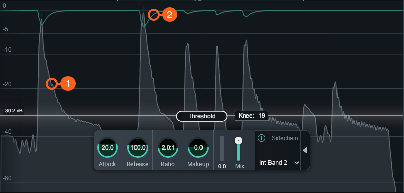
- Waveform Displays:
- Scrolling waveform: displays the amplitude of the input (uncompressed) and output (compressed) signals over time. The meter scrolls from right to left, with the most recent information on the right.
- Input waveform: the dark grey waveform displayed behind the output (wet) signal waveform.
- Output waveform: the light grey waveform displayed in front of the input (dry) signal waveform. When the signal is compressed, you can monitor the applied gain reduction compared to the input.
- Gain Reduction Trace: Draws a line that represents the gain reduction applied to the selected band over time. Use the Gain Reduction Trace to monitor and to set the response times (attack and release) and gain reduction envelope applied over time.
NOTE: AUTO GAIN ON THE OUTPUT WAVEFORM
Auto Gain adjusts the level of the compressed signal to compensate for any level difference between the uncompressed and compressed signals. The gain change introduced by auto gain is reflected in the output waveform, which may make it more difficult to differentiate between the input and output waveforms. The gain reduction trace meter can be useful for monitoring gain reduction over time when Auto Gain is enabled.
Controls
You can control compression by setting the Threshold and Knee.

Threshold
Determines the signal level at which the compressor begins processing.
- ADJUSTING THRESHOLD:
- Click and drag the Threshold slider handle up to increase the Threshold or down to decrease the Threshold.
- Click on the Threshold value readout text and manually enter a value in the inline edit field.
TIP: USE WAVEFORM DISPLAYS TO SET THRESHOLD
You can use the Waveform Displays as a visual guide when setting the threshold level for the compressor.
Knee
Adjust the knee value to set the desired character of the compression. The range of knee values provide different results:
- Higher knee values result in a “soft knee” setting with a subtle, natural sounding compression.
- Lower knee values result in a “hard knee” setting with an aggressive compression.
NOTE: Knee disabled in Vintage Mode
The Knee control is not adjustable when Vintage Mode is enabled.
HUD controls
The Compressor HUD controls work together to influence the character, amount, and speed of the compression applied to the input signal. The HUD controls available are:

Attack
Determines the amount of time it takes (in milliseconds) for the signal to become fully compressed after exceeding the threshold level.
Release
Adjust the amount of time (milliseconds) it takes for the Compressor to return to unity gain (recovers gain) when the input signal falls below the threshold, according to the rules set by the Level Detection Mode.
Ratio
Determines how much gain reduction will be applied to the entire signal or entire band when the threshold is crossed, according to the rules set by the Level Detection Mode.
NOTE: RATIO SETTINGS AFFECT COMPRESSION
Certain ratio settings and threshold setting will affect compression:
- A ratio setting of 1:1 will cause no attenuation upon signals that exceed the threshold.
- Ratio settings of 10:1 or greater will cause the compressor to function as a limiter.
- A ratio above 1.0 will cause compression. But, if you have a ratio below 1.0, it will cause the module to function as an Expander. When performing expansion in this way, the Gain Reduction Meter will show an inverted meter display.
Gain Reduction Meter
Displays the current instantaneous amount of gain reduction in decibels (dB) applied to the signal.
Makeup Gain
Determines the amount of static gain applied to the output signal after compression.
Mix
Adjust this slider to control the dry/wet mix of the direct, unprocessed signal with the processed signal for the associated band.
Advanced Controls
The Sidechain controls for the currently selected band are located in the Advanced panel of the HUD. To access the Advanced Panel, click the arrow button on the right hand side of the band HUD.
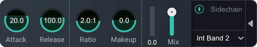
Sidechain
Allows you to trigger the amount of gain reduction in the compressor from a signal other than the input to the compressor. The signal is routed into the detection circuit of the compressor. Sidechained signal levels will control the amount of compression as defined by the threshold level. You can choose either an internal or external input signal to trigger the Compressor band’s dynamic behavior. By sidechaining, you can alter or improve the relationships between the elements of the mix so that they work together.
Enabled Sidechain
When you enable Sidechain, you have the option to sidechain with an internal band or an external band. The sidechain dropdown menu will display active internal bands and active external instances categorized under internal or external as described in the table below.
- INTERNAL (INT.): Choose from any band currently placed in the Compressor module.
- Using an internal sidechain input allows you to trigger gain reduction in the selected band from the amount of energy in a different band. For example, you can accentuate perceived low end energy by reducing high end any time the lowest band exceeds a defined threshold.
- Internal Full allows you to trigger gain reduction using the sonic information from all active bands.
- EXTERNAL (EXT.): Choose from any audio from another track or bus.
- Using an external sidechain input will help balance a signal with other tracks.
- The external audio source can also be filtered through any of the bands in the Compressor module by choosing any of the External bands (for example, Ext. Band 1).