
Ozone 8 Documentation
Ozone 8 Overview
What is Ozone 8?
Welcome to Ozone 8, the next installment of iZotope’s award-winning mastering software. Ozone 8 adopts unprecedented digital signal processing, machine learning, and assistive technology to bring you a robust set of mastering tools for starting, finishing, and delivering your music with superior quality.

The Design of Ozone 8
Ozone started by demystifying the “dark art” of mastering audio. More than fifteen years later, we are still pushing the boundaries of mastering and audio software to bring you the latest innovations.
In this version we’ve included new features that aim to enable your mastering by improving your workflow, suggesting custom settings, dealing with tonal balance and harshness, and communicating with other iZotope software. The technology in Ozone 8 shatters industry norms with the ambition of connecting you to your music in ways you’ve never experienced before.
Ozone 8 is the next generation of this acclaimed mastering suite. Our aim is that it will instill confidence in your audio production and inspire your creative endeavors.
Inter-plugin Communication with Neutron 2
With Ozone 8 we give you the ability to connect to Neutron 2 through the Tonal Balance Control plug-in because iZotope recognizes that the landscape of mixing and mastering in-the-box is starting to change. While concepting Ozone 8 and Neutron 2 we noticed that the entire process for most creatives takes place in a single workflow. Mixing, mastering, and most audio production all occur at the same time with the same hands. It begs the question, “Do these two worlds collide?” Our answer is yes, most definitely.
Ozone Application
Overview
Ozone 8’s standalone application allows you to use its mastering tools outside of your digital audio workstation.

Ozone App Interface
- Transport Bar: Includes playback controls and transport counter information.
- Track Tabs: Each tab represents an audio file and its associated settings within the current Ozone project.
- Waveform Display: A graphical representation of the currently selected track.
- Module Chain: A fully customizable signal chain for Ozone modules.
- Module Control Panel: Contains the controls and metering for the selected module.
- Presets: Opens the Preset Manager.
- Master Assistant: Opens the Master Assistant panel.
- Input/Output Section: Contains Input/Output Gain controls & metering.
- Audition Section: Contains Global Bypass, Gain Match, Sum to Mono, Swap Channels, Reference, Codec Preview [ADV], and Dither.
File Menu
Ozone’s file menu contains the different commands you use to perform functions such as:
- Importing audio files into an Ozone project for processing.
- Saving the project.
- Exporting the processed audio files.
Importing Audio
You can import up to 16 audio files into an Ozone project using the following methods:
- Click on the File menu at the top of the screen, then “Import Audio Files.”
- Click on the “plus” icon at the top-left area of the interface.
- Use keyboard shortcut Cmd+I or Ctrl+I; A standard dialog box will appear where you can navigate to the desired file, then click “Open” to import it into the project.
- Drag and drop audio files into the Ozone interface.
Supported Import File Types
| FILE FORMATS | BIT DEPTH(S) | SAMPLE RATE(S) |
|---|---|---|
| .wav | 16-bit | 11,250 Hz |
| .aiff | 20-bit | 22,050 Hz |
| .mp3 | 24-bit | 44,100 Hz |
| .aac | 48,000 Hz | |
| 88,200 Hz | ||
| 96,000 Hz | ||
| 176,400 Hz | ||
| 192,000 Hz |
Sample Rates
- The project sample rate defaults to the sample rate of the first file that is loaded.
- If a file is loaded after with a different or higher sample rate, it is converted to the original sampling rate set for the project by the first file, or manually set before the second file is loaded.
- The conversion process will not convert previously converted/processed files (which are copied as working files upon load); Ozone will simply go back to the original files, create new copies, and then convert all files to the new sample rate for their new working copies.
Exporting Audio
You can export processed audio files from the Ozone application using the following methods:
- Click on the File menu, and then select “Export Audio Files.”
- Use the keyboard shortcut Command+E (Mac) or Ctrl+E (Windows).
A dialog box will appear, offering various options for the files you are about to export.
Current Track vs. All Tracks
- Click on “Current Track” to only export the audio file in the currently highlighted tab.
- Click on “All Tracks” to export separate audio files for each audio file loaded into the current project.
Current Track

Filename (Available on Current Track Only)
Type the desired name into this field; the exported file will be labeled with the name you have typed.
All Tracks
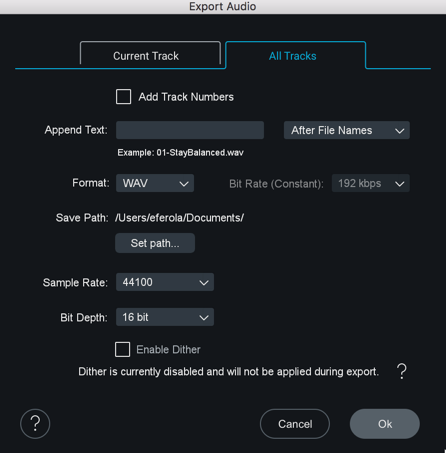
Append Text (Available on All Tracks Only)
Type in the desired text into the field; it will be automatically added to each of the exported tracks. You can also select whether to add the text before or after the file name. This function is useful for “tagging” the titles of a group of audio files with a common label; for example, you could append a group of files with a label such as “January 18th 2014 session.”
Add Track Numbers (Available on All Tracks Only)
You can add track numbers to your exports in the “All Tracks” section of the Export dialog. Select the “Add Track Numbers” checkbox and your exported files will be numbered in the order they appear in your Ozone project.
Format
Select the format of the exported file(s): WAV, AIFF, MP3, or AAC.
AAC & MP3 Codecs used by Ozone
For AAC Ozone uses Fraunhofer’s codec. For MP3 the LAME codec is used (www.mp3dev.org).
Bit Rate (Available on MP3 and AAC Only)
Set the bit rate for compressed file formats. Audio quality improves with increasing bit rate.
Save Path
Click on the Set Path button to select, through the resulting dialog box, where your exported audio file(s) will be saved.
- If the project is unsaved, the default save path is your Documents folder.
- If the project has already been saved, the default save path is an Exported Audio Files folder in the same location as the project.
Sample Rate
Select a sample rate to export your audio file. If you select a sample rate that differs from the original sample rate of the imported file, Ozone will apply high-quality sample rate conversion to the file.
Sample Rate when exporting to AAC or MP3 formats
Please note, if MP3 or AAC format is selected, files will be exported with a 44.1kHz sampling rate.
Bit Depth
Select a Bit Depth value for your audio file.
Enable Dither
Ozone processes files at 32-bit so dither is desirable for files being exported to values lower than 32-bit. When exporting to a bit depth lower than 32-bit, checking this box will apply high-quality dithering to the exported file.
This allows you to preserve the sound quality and dynamic range of a higher bit depth, when exporting the audio file to a lower bit depth.
For example, a common workflow is to record audio at 24-bit resolution, then import and process the audio in an application such as Ozone, which will process at a higher resolution of 32-bits.
However, if you are releasing the audio material on a commercial CD, it must be converted to 16-bit audio, the required bit depth of the “Red Book” CD audio format.
Help
Click this button to launch the help documentation for Ozone 8.
Cancel
Click this button to cancel the export process and return to the main interface.
Export
Click this button to begin the export process (or launch the Track Info screen for MP3 and AAC). A dialog box will appear that shows the progress of the export operation, which occurs faster than real time.
Track Info (Available for MP3 and AAC Only)
When MP3 or AAC is selected, the Track Info screen will appear after clicking Export. Here you can enter metadata for the encoded audio file that will used by MP3 & AAC players to display information about the file. MP3 will be tagged using ID3v2.3. AAC uses iTunes style tags.
Transport
Ozone provides Transport controls at the top of the interface, which allow you to easily navigate the playback functions of an imported audio file.
The transport bar includes the following functions:
Play
Start playback by clicking the Play button or pressing spacebar.
Stop
Click the Stop button to stop playback.
Return to Zero/Skip Back
The behavior of this button depends on the current position of the playhead:
- If the playhead is located more than two seconds into the audio file, clicking the button invokes a “return to Zero” function, moving the playhead back to the beginning of the current file.
- If the playhead is near the very beginning of the file, clicking the button acts as a “skip back” button, skipping back to the previous audio file.
Skip Forward
Click this button to skip to the next track tab in the project.
Playhead Follows Playback
Click this button to change the playhead behavior when playback is stopped.
When enabled, the playhead will stop at its current location on the timeline.
Loop
To loop playback of a specific section of audio, click and drag on the mouse and highlight a portion of the audio file; the section will highlight in blue and the “loop” icon in the transport bar will also highlight.
When you next press Play, the transport will loop playback repeatedly for the highlighted section only.
To stop looping audio, click on the Loop button again. The button will de-illuminate and looping will no longer be active, even though the area of the waveform will remain highlighted. The Loop button can be manually clicked again if you wish to again loop the audio.
Transport Readouts
Track Number
This number displays the track number of the currently selected track.
Time Counter
Displays the current time position within the audio file, displaying in minutes/seconds/milliseconds.
Total Time
This smaller display shows you the total length of all tracks in the project.
Multiple File Workflow
You can load up to 16 files into the same project and navigate to each file by clicking on the corresponding track tab.
Note
- Ozone only allows you to import a file once per project.
Re-ordering Tracks
Click and drag track tabs to change the order of tracks in the project.
Removing Tracks
You can remove tracks from a project using the following methods:
- Right-click on a track tab and select “Remove Track.”
- Click on a tab to highlight it, then click on the “X” button.
When removing a file, a dialog box will appear offering you three different options:
- Delete Removes the original file from the Imported Audio Files folder of the Ozone project directory.
- Keep Removes the track from the session, but retains the file in the Imported Audio Files folder of the Ozone project directory.
Saving Ozone Projects
An Ozone project contains the following components:
- An Ozone session file (.OZN).
- An Imported Audio Files folder.
- An Exported Audio Files folder.
Save Project As…
Creates a copy of the current project directory with a new name.
Ozone Session Files (.OZN)
An Ozone session file contains all of the session data including:
- Imported audio tracks
- Ozone module settings
- Track Trim & Fade settings
- Global I/O settings
Save (.OZN) As…
Saves a new copy of the session file within the current Ozone project directory. Useful for versioning your Ozone projects over time. Using this method will not create copies of the imported audio files, but instead will reference the files included in the Imported Audio Files folder of the current project directory.
Close Project
When closing a project, a dialog will appear with the following options:
- Cancel: Cancels out of the close operation; the current project will stay loaded.
- Don’t Save: All changes made since last save will be discarded.
- Save: All changes will be saved.
Create New Project
Creates a new Ozone project directory.
Open Project
Opens a previously saved Ozone project.
Edit Menu
Allows you to adjust Audio Device settings or open the Ozone Options window.
Audio Devices
Buffer Size
Adjusts the Buffer Size of the current Ozone session.
Output Devices
Selects the hardware device used by the Ozone session to play back audio.
Preset System
Overview
Ozone features a preset manager that allows you to quickly and easily work with presets.
Factory Content
Ozone 8 Global Factory presets are organized into the following folders:
- ALL PURPOSE MASTERING
- GENRE-SPECIFIC MASTERING
- INSTRUMENTS AND BUSSES
- SIGNATURE PRESETS
General Functions
Loading Presets
You can select and audition any preset by clicking on the name in the list. This will activate the relevant selected Ozone modules, and you will hear the effect of the preset when you play back your audio. You can easily compare several different presets just by picking a different name on the list.
Renaming Presets
In the Preset Manager you can double click on a preset to edit its name.
Show at Startup
By default the preset manager will open automatically at startup. If you do not wish for this to occur, uncheck the “show at startup” box at the bottom of the presets window.
Working Settings
Working Settings allow you to recall a preset that hss been modified but not saved.
Default
Loads the Factory default state or your custom default preset.
Controls
Add
Click the Add button to create a new preset. The Preset Manager has a comments section for additional detail.
Special characters in Preset Names
- Some characters such as * or / cannot be used as preset names. If you try to type these characters in the name they will be ignored.
Delete
To permanently delete a preset, select the preset from the list and click the Delete button.
New
Click the folder button to create a new preset folder.
Change Folder
Click the Change button to select the preset folder path.
Ozone Factory Preset Paths
By default, Ozone preset files are stored in:
- Windows: C:\Users\userName\Documents\iZotope\Ozone 8\Presets
- Mac: Users/userName/Documents/iZotope/Ozone 8/Presets/
Save
Click Save to store changes made to the current preset.
Dirty state flag ( * )
- An asterisk ( * ) will appear next to a preset that has been modified but not saved.
Close
Click the Close button to hide the Preset Manager window.
Custom Default
Right-click on any preset in the Preset Manager and select “Set [Preset Name] As
To undo this action, you can right-click on any preset and select “Reset
Right-click on the
Module Preset System
Module presets allow you to easily save and load settings in individual modules without affecting other modules in the signal chain. Ozone 8 module and component plug-in presets are interchangeable, so Ozone 8 Advanced users can make use of their module presets within the component plug-ins and vice versa.
Opening the Module Preset System
The Module Preset system is accessible from the Ozone signal chain. Clicking on the button directly above a module’s Solo button will open the Module Preset window.
Loading Module Presets
Selecting a preset in the Module Preset window will load the settings and related comments.
Saving Module Presets
Click the Add button in the Module Preset window to a new module preset.
Updating Module Presets
The Module Preset window does not include a Save button. Click the Add button to create a new preset from the module’s current settings.
Deleting Module Presets
Select a module preset and click the Delete button to remove the preset file from the preset folder on your computer. This will move the module preset file to the Trash/Recycle Bin.
Changing the Module Presets Folder
Click the Change button to change the module preset folder path.
The default file paths for the module presets are in the following locations:
Windows Module Preset file paths:
- C:\Users\userName\Documents\iZotope\Ozone 8\Presets\Dynamic EQ Presets
- C:\Users\userName\Documents\iZotope\Ozone 8\Presets\Dynamics Presets
- C:\Users\userName\Documents\iZotope\Ozone 8\Presets\EQ Presets
- C:\Users\userName\Documents\iZotope\Ozone 8\Presets\Exciter Presets
- C:\Users\userName\Documents\iZotope\Ozone 8\Presets\Imager Presets
- C:\Users\userName\Documents\iZotope\Ozone 8\Presets\Maximizer Presets
- C:\Users\userName\Documents\iZotope\Ozone 8\Presets\Spectral Shaper Presets
- C:\Users\userName\Documents\iZotope\Ozone 8\Presets\Vintage Compressor Presets
- C:\Users\userName\Documents\iZotope\Ozone 8\Presets\Vintage Limiter Presets
- C:\Users\userName\Documents\iZotope\Ozone 8\Presets\Vintage EQ Presets
- C:\Users\userName\Documents\iZotope\Ozone 8\Presets\Vintage Tape Presets
Mac Module Preset file paths:
- Users/userName/Documents/iZotope/Ozone 8/Presets/Dynamic EQ Presets
- Users/userName/Documents/iZotope/Ozone 8/Presets/Dynamics Presets
- Users/userName/Documents/iZotope/Ozone 8/Presets/EQ Presets
- Users/userName/Documents/iZotope/Ozone 8/Presets/Exciter Presets
- Users/userName/Documents/iZotope/Ozone 8/Presets/Imager Presets
- Users/userName/Documents/iZotope/Ozone 8/Presets/Maximizer Presets
- Users/userName/Documents/iZotope/Ozone 8/Presets/Spectral Shaper Presets
- Users/userName/Documents/iZotope/Ozone 8/Presets/Vintage Compressor Presets
- Users/userName/Documents/iZotope/Ozone 8/Presets/Vintage Limiter Presets
- Users/userName/Documents/iZotope/Ozone 8/Presets/Vintage EQ Presets
- Users/userName/Documents/iZotope/Ozone 8/Presets/Vintage Tape Presets
General Functions
Undo History

All modifications to parameters in Ozone are captured in this list. Click any entry in this list to revert to a previous state of Ozone.
| Control | Description |
|---|---|
| CLEAR | Removes all actions from the history list. Clearing the history list does not affect parameters, it simply removes existing entries from the list. |
| CLOSE | Hides the Undo History window. |
| A/B/C/D | Allows you to set four history snapshot states. Snapshots allow you to quickly toggle between different processing states to compare changes. Assign an event in the history list to a snapshot button by selecting the event in the list and clicking the “Set” button below a snapshot button. |
Module Chain
Ozone’s active modules are loaded into the horizontal signal chain along the top of the interface.

Click, hold, and drag modules horizontally to change their order in the signal chain. More information about the Module Chain can be found in the Common Module Controls chapter.
Module/Plug-in Browser
You can view and add Ozone modules or VST & AU plug-ins by opening the module browser screen. The module browser can be opened by clicking on the ‘+’ space in the module chain.
Notes about the module chain
- The Ozone module chain only supports up to 6 modules at a time. The module browser is not accessible when the module chain is full. Remove a module from the chain to access the module browser.
- VST & AU plug-ins can only be added to the module chain in the Ozone application.
- Ozone component plug-ins do not include a module chain. This functionality is available in the main Ozone plug-in and Ozone application only.
Ozone Modules
The module browser displays all available Ozone modules. If a module has already been added to the module chain, the icon for the module will be greyed out.
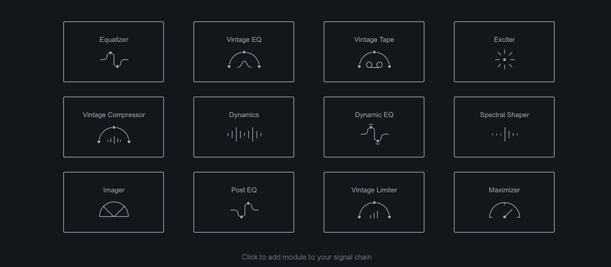
Note
- Ozone modules cannot be added more than once to the same module chain.
Plug-ins (Ozone App Only)
You can view and add plug-ins to the module chain in the Ozone application by clicking on the “Plug-ins” tab in the Module browser view.

You can manage plug-in related options by clicking on the gear icon that appears when the “Plug-ins” tab is selected. The Plug-in options tab allows you to enable or disable plug-in formats, configure custom VST plug-in paths and manually start plug-in scanning. When plug-in formats are enabled, the Ozone application will scan for new plug-ins in the background every time it is opened.
Global I/O Meters & Gain
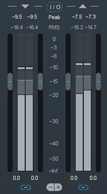
Ozone’s input/output level meters display the input and output level for the left and right channels. Several metering options are available; you can select which metering method you wish to use by opening the I/O options tab in the Options menu, or clicking on the I/O button above the I/O meters (this contains limited options, refer to the I/O tab of the Options menu for more options.)
Setting Input and Output
You can adjust the input or output gain by sliding the faders with the mouse, as well as clicking and using the mouse wheel.
Unlinked Gain Adjustments
By default, the left and right gain levels are linked; moving one moves the other. You can adjust left and right gain independently by clicking on the Link icon below the meters. You can also offset the two channels and then relink them, so that later adjustments move both channels by the same amount. The faders will remember their offset, even if they are temporarily turned up or down all the way, so that when you bring the faders back to the middle the offset will be preserved.
Double-Click to Reset Faders
If the left and right faders are locked, double-clicking on either fader will reset both of them to 0 dB. If the left and right faders are unlocked and set at different levels, double-clicking a specific fader will reset it to 0 dB.
If the left and right faders are locked but had been previously been set to different levels, double-clicking on a fader will reset it to match the level of the other fader. Another double-click will reset both faders to 0 dB.
Setting the Scale of the Meters
You can further customize your metering by adjusting the scale of the input and output meters.
- Clicking the “(+)” sign below the meters will increase the zoom or resolution of the metering scale.
- Clicking the “(-)” sign will decrease or zoom out the resolution of the metering scale.
Auditioning Tools
Ozone’s audition section is located underneath the input and output meters on the right-hand side of the screen.
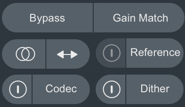
The following controls are available in the auditioning section:
Bypass
Toggles all Ozone processing on or off. When enabled, the module controls will be dimmed by an overlay to indicate that Ozone is bypassed.
Gain Match
You can change the behavior of Gain Matching in the Ozone options menu.
Sum to Mono
Collapses the stereo signal to mono, allowing you to check your song for mono compatibility. It is always important to check any stereo material for mono compatibility, and make sure that any processing you have done does not cause any elements of your mix to “cancel out” and disappear when listening in mono.
Swap Button
Swaps the left and right sides of the stereo signal.
Codec Preview [ADV]
Opens the Codec Preview panel. See the Codec Preview chapter for more information about this panel.
Dither
Opens the Dither panel. See the Dither chapter for more information about this panel.
Reference
Open the Reference panel. See the Track Referencing chapter for more information about this panel.
Common Module Controls
Overview
There are a number of features shared across Ozone modules. This chapter defines these features and their respective workflows.
Module Chain

The signal chain in Ozone allows up to 6 modules at at time. The module chain is not available in the component plug-ins.
The following table outlines module chain options:
| Icon | Name | Description |
|---|---|---|
 |
Add | When module slots are available, click on this space to view the module selection screen. Click on an available module in the module selection screen to add it to the module chain. |
 |
Remove | Removes the associated module from the module chain. |
 |
Module Preset | Opens the Module Preset window. See the Module Preset section for more information. |
 |
Solo | Auditions the processing of the associated module. When a module solo is enabled, all other module processing will be bypassed. Note that the global controls (I/O gain & Auditioning controls) still affect the output when a module solo is enabled. You can Solo one module at a time. |
 |
Bypass | Toggles the processing of the associated module on and off. You can bypass multiple modules simultaneously. When a module is bypassed, the module icon and name will be greyed out. |
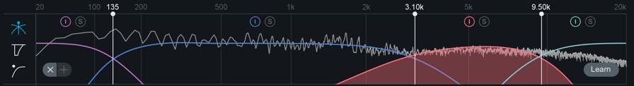
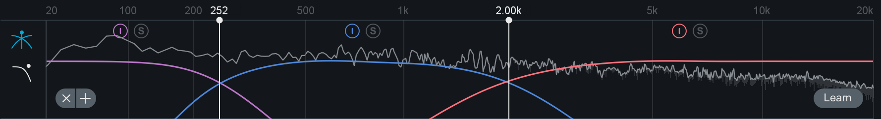
Multiband Modules
Ozone offers multiband processing in the following modules:
Multiband Modules allow you to apply frequency dependent processing to your music. You can use up to 4 separate bands and adjust the crossovers by interacting with the handles in the minispectrum view.
Crossovers
Multiband modules offer controls for adjusting and auditioning the crossover frequency bands in the crossover mini-spectrum metering view.
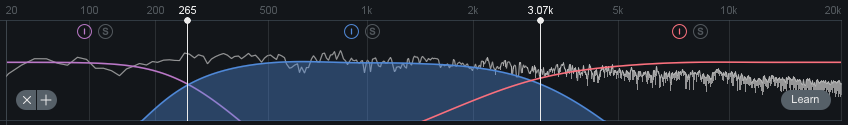
Adjusting Crossover Cutoffs
The multiband crossover points can be manually adjusted in the crossover mini-spectrum view. Crossover cutoff points can be manually adjusted using the following methods:
- CLICK & DRAG CUTOFF HANDLES Crossover cutoffs can be adjusted by hovering over the white crossover handle, left-clicking and dragging the handle to the desired position. The cursor will change to display a left/right arrow icon when hovering over the adjustable crossover cutoff handle.
- TEXT INPUT Double-clicking on a crossover cutoffs value readout (white text directly above the cutoff handle) will open an inline edit field. Type the desired frequency value for the crossover cutoff into this field and hit the Enter or Return key to update the value.
Note
- Crossover cutoff points are not shared across multiband modules. Adjusting a crossover point in one module will not affect the crossover points in other multiband modules.
Crossover View Controls
The following table outlines the common controls available in the multiband crossover view.
| Icon | Name | Description |
|---|---|---|
    |
Band Power | Toggles the processing of the associated band on and off. You can bypass multiple bands simultaneously. When a band is bypassed, the band power icon will appear greyed out. |
    |
Band Solo | Auditions the output of the associated band. You can solo multiple bands simultaneously. When a band solo is not active, the associated solo button will appear greyed out. |
 |
Remove Band | Clicking the x button will remove a band. Note: the band will be removed from right to left. |
 |
Add Band | Clicking the + button will insert a new band. Note multiband modules support up to 4 bands of processing. |
 |
Learn | When enabled, the crossover points will be automatically adjusted based on the incoming audio. See the “Crossover Learn” section below for more information. |
Tip: Soloing bands
- You can Solo the dry output (pre-processing) of a frequency band by bypassing and soloing the band at the same time. This can be useful for auditioning the affect of an individual band’s processing.
Crossover Learn
Ozone multiband modules include an innovative Learn function for determining crossover points. When enabled, the Crossover Learn function will search for natural crossover cutoff points for frequency bands using a few criteria, including identifying minima in the frequency spectrum of the incoming audio.
When the Learn function is active the button will turn blue. When it has determined the ideal values for the crossover cutoffs, it will turn itself off automatically. You can also manually disable learning when it is active by clicking the Learn button again.
Crossover Learn Notes
- For crossover learning to behave as expected, the module must be receiving audio input while Learn is engaged.
- The Crossover Learn button is only available in the crossover mini-spectrum view of multiband capable modules.
- The Learn button will not appear in the crossover mini-spectrum view if only one band is enabled in a multiband capable module.
Crossover Context Menu Options
Right-clicking (or Option+Left-clicking) on the crossover spectrum view in multiband modules will expose the following options in a context menu:
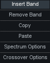
- INSERT BAND: Adds a band to the current multiband module. You can add up to 4 bands in each multiband module.
- When adding bands using the context menu ‘Insert Band’ option, the crossover point will be placed at the point in the spectrum you right-clicked on.
- Note: If a crossover exists at the point you right-clicked on, the new crossover cutoff will be placed to the right of the existing cutoff.
- REMOVE BAND: Removes a band from the current multiband module.
- When removing bands using the ‘Remove Band’ context menu option, the first crossover point to the right of where you right-clicked will be removed.
- COPY: Copies the settings of the band that was right-clicked on to the clipboard.
- PASTE: Pastes relevant band settings from the clipboard to the band that was right-clicked on.
- Note: You can only paste band settings that were copied from the same multiband module.
- SPECTRUM OPTIONS: Navigates to the Ozone Spectrum Options tab.
- CROSSOVER OPTIONS: Navigates to the Crossover Options tab for the current module. For more information on the different Crossover Types, see the following section.
Crossover Types
Each multiband module has independently configurable crossover types. You can change the crossover type used by a given module in the Options menu.
Each multiband module offers the following crossover types:
- ANALOG: The analog crossover option provides a natural character reminiscent of filter slopes in analog equipment.
- HYBRID: This perfect reconstruction IIR (Infinite Impulse Response) analog crossover is designed to reduce phase distortion and frequency distortion found in other analog crossovers while maintaining precise crossover points and the warm characteristics of analog crossovers.
- DIGITAL: Ozone 3 first introduced the option of digital linear-phase crossovers. These provide a more accurate and transparent sound.
Digital Crossover Options
When the Digital Crossover Type is selected, the following options also become available:
- CROSSOVER BUFFER SIZE: Sets the buffer size for the digital crossover. See Buffer Sizes for more info.
- CROSSOVER Q: You can adjust the bandwidth, or Q, of the crossover filters with this control. A higher Q results in tighter crossovers, while a lower Q provides a more gradual transition from one band to the next. This is only available for the digital crossover.
Module Channel Processing Modes
Ozone offers different processing modes that determine how processing is applied in a given module. When a module supports more than one processing mode, processing mode options will appear on the left hand side of the module control area.
The following Ozone modules offer different module channel processing options:
| MODULE | STEREO | M/S | L/R |
|---|---|---|---|
| Dynamics | YES | YES | NO |
| Dynamic EQ | YES | YES | YES |
| EQ | YES | YES | YES |
| Exciter | YES | YES | NO |
| Spectral Shaper | YES | YES | NO |
| Vintage Compressor | YES | YES | NO |
| Vintage EQ | YES | YES | YES |
Stereo Mode
Stereo mode is the default processing mode for all modules. This also applies to modules that do not offer explicit Mid/Side or Left/Right processing options.
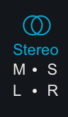
When Stereo mode is selected, one set of controls will be available for processing in the selected module.
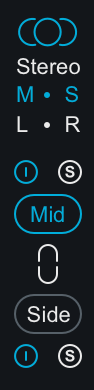
Mid/Side (M/S) Mode
Mid/Side processing is enabled by selecting the M-S processing mode button on the left side of the module control area.
Mid/Side Processing Examples
For more information about Mid/Side processing, see the Tips & Examples chapter.
Mid/Side Encoding & Decoding
When Mid/Side mode is enabled, the input signal to the module is encoded into a Mid/Side configuration. After processing in Mid/Side mode, the signal is decoded from Mid/Side to Stereo at the output of the module.
- Mid Channel Encoding: The encoded Mid channel signal represents the phantom image between left & right speakers, or the center channel of the input audio.
- Side Channel Encoding: The encoded Side channel signal represents the sides (or edges) of the input audio.
Independent Mid & Side Control Adjustments
Selecting Mid/Side mode will expose two unique sets of parameters for processing. One set of parameters applies processing to the encoded Mid channel and the second set of parameters applies processing to the encoded Side channel.
Mid Channel Controls
- View & Adjust Mid Channel Controls Select the “Mid” button to independently view and adjust the parameters that affect the Mid channel processing of the active module.
- Bypass Mid Channel Processing Deselect the power button above the Mid channel selector to Bypass the Mid channel processing.
- Solo Mid Channel Processing Select the ’S’ button above the Mid channel selector to solo the module’s Mid channel processing.
Side Channel Controls
- View & Adjust Side Channel Controls Select the “Side” button to independently view and adjust the parameters that affect the Side channel processing in the active module.
- Bypass Side Channel Processing Deselect the power button below the Side channel selector to Bypass the Side channel processing.
- Solo Side Channel Processing Select the ’S’ button below the Side channel selector to solo the module’s Side channel processing.
Linked Mid/Side Control Adjustments
You can easily link Mid & Side controls by enabling the ‘Link’ button between the Mid & Side selection buttons. When Link is enabled, parameter adjustments in the Mid channel will adjust the corresponding Side channel parameter and vice versa.
More information: Relative Parameter Linking
See the Tips & Examples chapter for more information about parameter linking in Ozone.
Mid/Side Metering
Ozone’s I/O meters display Stereo information by default. To change the Input/Output meters to display Mid/Side metering information, click on the I/O button above the I/O meters and change “Source” selection to Mid/Side.

When the I/O meters are in Mid/Side mode, the meter in the center represents the Mid channel level information and the meters on the left and right represents Side channel level information. The left and right gain sliders control the left and right gain of your signal, regardless of the Meter Source selection.
Left/Right (L/R) Mode
Left/Right processing is enabled by selecting the L-R processing mode button on the left side of the module control area.
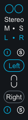
When enabled, the input signal to the module is split into two processing channels, Left & Right. The signal is ‘summed’ back to Stereo at the module’s output.
Independent Left & Right Control Adjustments
Selecting Left/Right mode will expose two unique sets of parameters for processing. One set of parameters applies processing to the Left channel and the second set of parameters applies processing to the Right channel.
Left Channel Controls
- View & Adjust Left Channel Controls Select the “Left” button to independently view and adjust the parameters that affect the Left channel processing of the active module.
- Bypass Left Channel Processing Deselect the power button above the Left channel selector to Bypass the Left channel processing.
- Solo Left Channel Processing Select the ’S’ button above the Left channel selector to solo the module’s Left channel processing.
Right Channel Controls
- View & Adjust Right Channel Controls Select the “Right” button to independently view and adjust the parameters that affect the Right channel processing of the active module.
- Bypass Right Channel Processing Deselect the power button below the Right channel selector to Bypass the Right channel processing.
- Solo Right Channel Processing Select the ’S’ button above the Right channel selector to solo the module’s Right channel processing.
Linked Left/Right Control Adjustments
You can easily link Left & Right controls by enabling the ‘Link’ button between the Left & Right selection buttons.
When Link is enabled, parameter adjustments in the Left channel will adjust the corresponding Right channel parameter and vice versa.
More information: Relative Parameter Linking
See the Tips & Examples chapter for more information about parameter linking in Ozone.
Dynamics
Overview
One of the most powerful modules in Ozone is the Dynamics module. You can use this module to shape the dynamics of your mix, with up to four bands of analog-modeled compression, limiting, and expansion. Dynamics is also available as a component plug-in of Ozone 8 Advanced.

Global Controls
Single Band/All Bands Display
Toggles between All Bands view and Single Band view. When Single Band view is selected, you can use the arrows to the left or right of the band icon to cycle through the enabled bands.
Link Bands
When enabled, adjustments made to a control in one band will adjust the corresponding control in all other bands of the Dynamics module by the same amount.
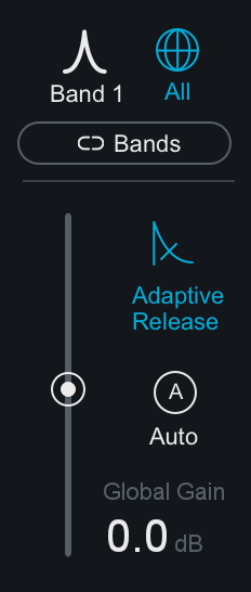
Adaptive Release
When Adaptive Release is On in the Dynamics module, it will automatically adjust the Release time of the Compressor based on the Peak factor of a signal. If a transient signal is detected, the Release time is scaled to be shorter for less pumping. If a sustained note is detected, the Release time is scaled to be longer for lower distortion.
The Release time is scaled in relation to the Release value set by the user. For example: if you are using the Compressor with the Release time set to 100 ms, the Release time will be automatically adjusted to a value within a range of 20 ms to 200 ms, depending on the type of signal that is being processed.
Gain
- IN ALL BANDS VIEW: The Gain slider affects the gain of the entire Dynamics module after processing. This is useful for applying make-up to compensate for any loss in level after compression has been applied.
- IN SINGLE BAND VIEW: The Gain slider will affect the output gain of the currently selected band after processing.
Auto
When enabled, make-up gain will automatically be calculated and applied to the output signal to compensate for level differences introduced by dynamics processing.
The automatic gain control calculates the RMS levels of the input and output signals independently for each Dynamics crossover band. Gain is automatically applied to the output signal based on the RMS level difference between the input and output signals.
This control acts as a smart “make-up gain” control that will adapt the post-processing level to match the pre-processing input level over time. This can be a useful tool for A/B’ing various settings in the multiband Dynamics module without having gain changes affect your perception.
Auto & Manual Gain Adjustments
- Auto mode and manual band/global gain adjustments can be applied simultaneously.
Level Detection Mode
The 3 buttons below the threshold input meters control the global level detection mode for the Dynamics module.
- PEAK: When this option is enabled Ozone’s detection circuit looks at peak levels of the incoming signal. In general, this setting is useful when you are trying to even out sudden peaks in your music.
- RMS: When this option is enabled, Ozone looks at the average level of the incoming signal. RMS detection is useful when you are trying to increase the overall volume level without changing the character of the sound.
- ENVELOPE: Envelope mode behaves much like RMS mode, but with some key advantages. Unlike RMS, Envelope mode produces even levels across all frequencies. Additionally, Envelope mode will not produce the aliasing or artifacts that RMS detection can cause.
Parallel
Adjust this slider to control the dry/wet mix of direct, unprocessed signal to the processed signal for the current band. This slider is very useful for applying the technique called “parallel compression” where you can mix in a desired amount of unprocessed signal.
Per Band Controls
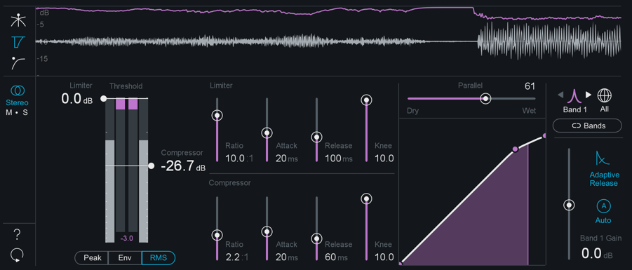
Threshold
Adjust the threshold of the limiter and compressor to set the level at which the dynamics processing is triggered.
Ratio
Both the Limiter and Compressor have their own ratio control. Higher ratios will result in more extreme compression. When the Compressor or Limter’s ratio is set to a negative number, it will act as an expanders.
Attack & Release
Adjust the attack and release controls to set how quickly the dynamics processor reacts to audio that crosses the threshold.
- ATTACK determines how quickly the dynamic processor reacts when the threshold is reached.
- RELEASE determines the amount of time before the dynamics processor returns the level to normal once the signal is no longer above the threshold.
Knee
Adjust this control to set the desired character of the compression.
- Higher settings result in a “soft knee” setting with a subtler, natural sounding compression.
- Lower settings result in a “hard knee” setting with a more aggressive sounding compression, often used as an intended effect on individual tracks such as kick and snare drum.
Mid/Side Processing
The Dynamics module can operate in either Stereo or Mid/Side operation. See the Mid/Side Processing section for more details.
Meters
Threshold Meter
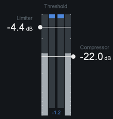
The Threshold meter displays the input level into the detection circuit (displayed in grey) alongside the gain reduction occuring as a result of the dynamics processing (displayed in the corresponding band color).
Dynamic Curve Meter

This meter shows the input signal (x axis) plotted against the output (processed) signal (y axis). Lowering the horizontal compression control add more compression to the signal.
You can zoom in and out on the meter by clicking the “+” and “-” buttons in the bottom right.
The meter features individual nodes for the Limiter ( L ) and Compressor ( C ). These nodes are linked to the Threshold and Ratio controls, and can be used to adjust the curve in a visual way, rather than setting them with the standard controls.
Mini-meter View
The Dynamics module offers 3 different mini-metering views along the top of the controls panel.
Crossover
This view displays a spectrum analyzer and multiband crossover controls. For more information about using the crossover view, see the Common Module Controls chapter.
Detection Filter
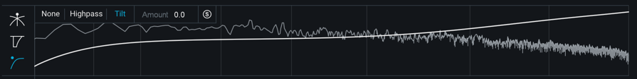
This view allows you to modify the frequency response of the detection circuit used for the dynamics processing, so that it responds more or less to input in different frequency ranges.
The following controls are available in the Detection Filter view:
- NONE: No filter is applied to the dynamics module detection circuit.
- HIGHPASS: A high-pass filter is applied to the dynamics detection circuit.
- SLOPE: Click on the Slope value readout to toggle between the different Slope values. The Highpass detection filter includes the following Slope options: 6 dB, 12 dB, 24 dB, 48 dB.
- Click and drag the frequency node to adjust the frequency of th highpass filter.
- TILT: Similar to the THRUST circuit found on API compressors, Tilt mode preserves low frequencies using a high-frequency weighted filter curve. Adjusting the ‘Amount’ will modify the slope of the Tilt filter.
- SOLO: Clicking on the ’S’ button will audition the input to the detection filter. This allows you to listen to only the signal that is triggering processing in the Dynamics module.
Gain Reduction Trace
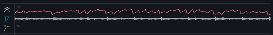
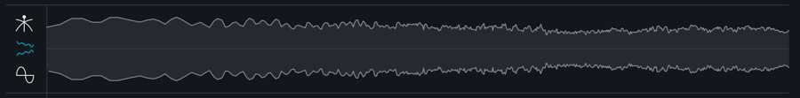
This view features a waveform display and a scrolling trace that indicates the amount of gain reduction applied by the dynamics processing over time.
When using the Dynamics module in multiband mode, the gain reduction trace displays the waveform and gain reduction trace for the currently selected band only. The trace color will reflect the color of the currently selected band.
The Gain Reduction Trace can help you to set attack and release controls appropriately and monitor the envelope of gain reduction.
Gain reduction trace scale
- Adjust the gain reduction trace scale on the left of the meter by hovering over it and using the mousewheel to zoom in or out.
- Adjust the visible range of the scale by clicking and dragging up or down.
- Reset the scale to the default zoom level by double-clicking.
Dynamic EQ
Overview
This processor can be very useful in controlling specific frequencies in your mix that are too loud, with a degree of precision not possible with a static EQ.

Controls
Global EQ Filter Mode
Selects the EQ processing type used for the Dynamic EQ, this setting is global and applies to all Dynamic EQ bands.
- ANALOG: Uses a minimum-phase FIR (Finite Impulse Response) filter, which is useful in a variety of situations.
- DIGITAL: Uses a linear-phase IIR (Infinite Impulse Response) filter, which retains the phase of the original signal, but uses more CPU.
Filter Shape
Each band of the Dynamic EQ offers the following filter shapes:
- Baxandall Bass
- Band Shelf
- Peak Bell
- Proportional Q
- Baxandall Treble
Frequency/Gain
You can adjust an EQ band by clicking on a node and dragging it horizontally to change the frequency, and vertically to change the gain of the band.
Q (Bandwidth)
You can adjust the Q or bandwidth of any band by dragging the “handles” on the side of the node. If you have a wheel mouse, you can use the mouse wheel to widen/narrow a selected band while hovering over the node.
Threshold
Drag the threshold to adjust the amount of compression applied to the specific EQ band you have selected.
Dynamic Trigger Mode
- UP: When a signal exceeds the threshold, the filter will move upwards.
- If the static gain value is positive: using the Up trigger mode will move the filter from the center line toward the static node (boost when triggered).
- If the static gain value is negative: using the Up trigger mode will apply the full negative gain until it is triggered–when triggered it will move toward the center line.
- DOWN: When a signal exceeds the threshold, the filter will move downwards.
- If the static gain value is positive: using the Down trigger mode will move the filter from the static boost value toward the center line (cut when triggered).
- If the static gain value is negative: using the Down trigger mode will move the filter from the center line toward the static negative gain value.
Attack
Adjusts how long it takes a band’s dynamic trigger to react to a signal crossing the Threshold value. You can adjust the Attack value by clicking and dragging on the value readout or by double-clicking on the value readout and manually entering a value.
Release
Adjusts how long it takes for the associated band’s dynamic trigger to return the filter to the static settings when a signal falls below the Threshold value. You can adjust the Release value by clicking and dragging on the value readout or by double-clicking on the value readout and manually entering a value.
Auto Scale
When enabled, the displayed Attack & Release values are scaled automatically based on the band’s frequency value.
Offset
Sets a static gain offset for the associated band.
Equalizer
Overview
Ozone’s versatile Equalizer allows you to add warmth and character with analog-matched filters, or precisely boost and cut frequencies with digital linear-phase filters. In the main Ozone plug-in and Ozone application, you have access to two EQ modules: EQ & Post EQ. The EQ is also available as a component plug-in of Ozone 8 Advanced.

EQ Views
Ozone’s EQ module contains three different views for working with the EQ.
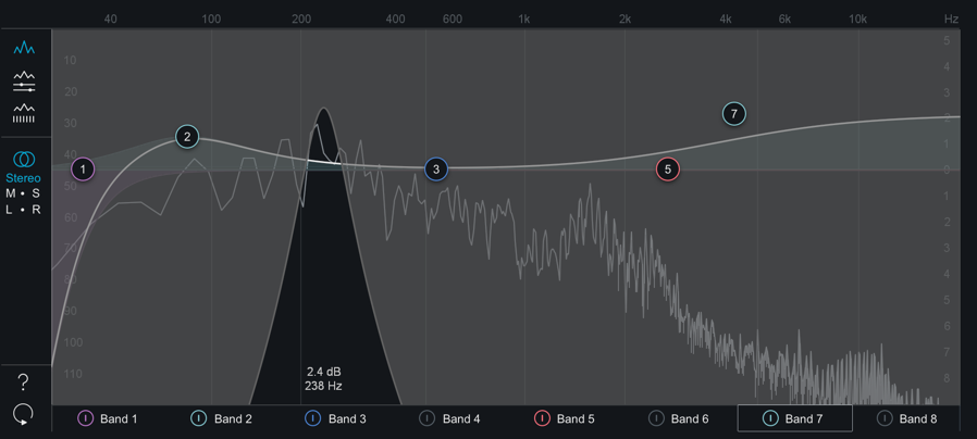
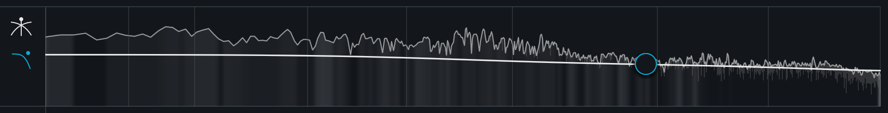
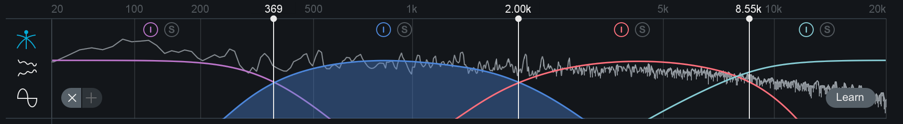
##Spectrum View

This view offers an expanded spectrum display area and minimized band parameter details. Band parameters can be adjusted by interacting with the EQ nodes of enabled bands. You can enable or disable bands by clicking the power buttons along the bottom of the spectrum display. As you adjust the nodes you will see different curves. The white curve is the composite of all EQ bands, while the selected band shows as a thin line in the band’s specific color.
Adjusting EQ Band Parameters in the Spectrum View
- FREQUENCY: Dragging an EQ node left or right adjusts the frequency.
- GAIN: Dragging an EQ node up or down adjusts the gain.
- Q (BANDWIDTH): Adjusting the “handles” that appear to the left and right of a selected node will adjust the Q value of the associated band. You can click and drag the Q handles to adjust the value, or use the mousewheel when hovering over the selected node in the spectrum area to adjust the Q value.
- FILTER SHAPE: Right-clicking on an EQ node will display a context menu with filter shape options. The currently selected filter shape will be highlighted when you first open the context menu. You can change the selected filter shape for the associated band by choosing the new filter shape from the context menu. The context menu will hide itself when the filter shape selection has been changed, or if you click elsewhere in the interface without modifying the filter shape selection.
All Bands View
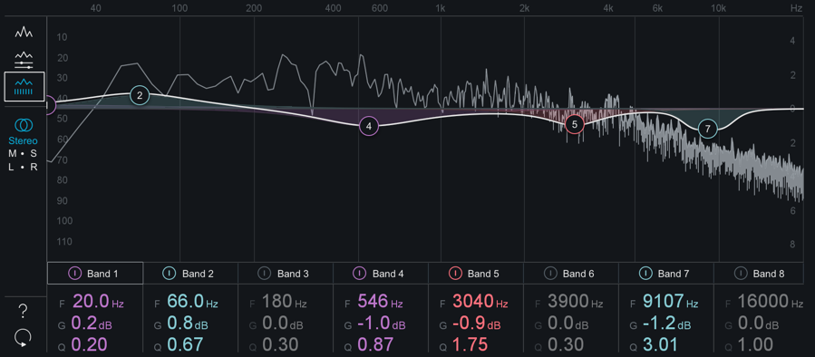
This view provides an overview of basic parameter values for each band. You can adjust the Frequency, Gain or Q values for any band by:
- Clicking and dragging (up/down or left/right) on the value readout.
- Double-clicking on a value readout and manually entering a new value.
Detailed Band View
This view displays detailed parameter information for the selected band tab. This is the default EQ view selection.
Controls
There are many powerful controls available for adjustment in the EQ module. Depending on the selected view, some controls may be hidden from view. You can change views to gain access to controls or make adjustments to select band parameters using the EQ nodes in the spectrum area.
Global EQ Filter Mode
Sets the global EQ filter algorithm.
- ANALOG: Emulates classic analog EQ sounds with added coloring. This mode utilizes IIR (Infinite Impulse Response) filters.
- DIGITAL: More precise, clinical-sounding EQ models. This mode utilizes FIR (Finite Impulse Response) filters.
When Digital mode is enabled, two additional parameters become available:
- PHASE When using the Equalizer in Digital mode, you have access to a phase slider for each of the EQ bands. When the Phase slider is set to 0%, the currently selected band will have a Linear phase response. When the Phase slider is set to 100%, the currently selected band will have a Minimum phase response.
- SURGICAL MODE Enabling Surgical Mode changes the filter curves to less musical, but far more precise shapes.
Filter Shapes
In both Analog and Digital modes, Ozone provides the ability to set the type or shape of any of the eight EQ nodes. Any node can be set to any of the following types of EQ filter types:
- The Low-Pass and High-Pass filters are Butterworth filters; optimized for maximum flatness without ripple or resonance in the passband or stopband.
- The Brickwall Low-Pass/High-Pass filters are elliptic filters; optimized for steepness with minimal ripple in the passband and stopband.
- The Vintage-type filters exhibit a complimentary frequency dip, modeled after the renowned Pultec analog Equalizer, creating a complex slope with one node.
Frequency/Gain/Q (Bandwidth)
Individual parameter adjust mode also lets you adjust the frequency, gain, and bandwidth for the currently selected band. You can adjust them graphically, as with the Spectrum View, but in this view you can also adjust them by clicking and dragging on the numerical parameters (frequency/gain) and the numerical parameter (bandwidth, aka Q).
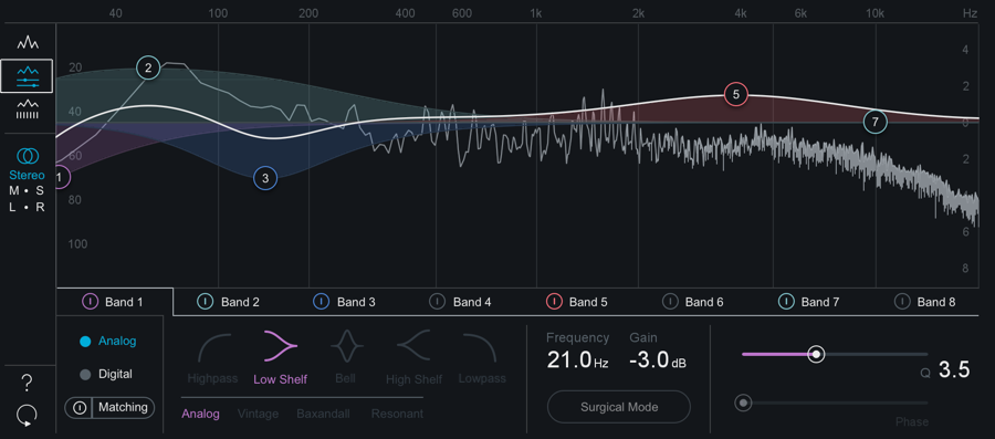
Matching EQ
The Matching EQ is a digital linear-phase EQ, with the ability to use over 8,000 bands of frequencies for very precise matching.
Workflow
To access the Matching EQ panel, navigate to the Detailed Band View of the EQ and click the Matching button (directly below the Analog/Digital buttons).
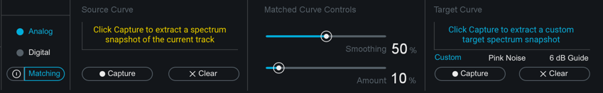
Capture A Source Curve
Press the Capture button under the Source curve header and playback the track you are working on to begin taking a snapshot. Press the Stop button to stop capturing and freeze the current shape of the curve.
After the Source curve is captured, the resulting curve will be displayed in yellow in the EQ spectrum area.
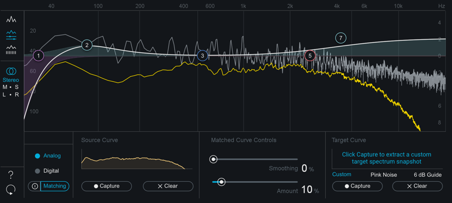
If you aren’t happy with the curve you captured, press the Clear button to clear the source curve and try again.
Capture/Select A Target Curve
If you have a track you’d like to match your curve to, choose the “Custom” option. Import the track and ensure the audio will pass through Ozone. In the application, you can import the target track to your session and capture the curve when that track tab is selected. All tracks share a common target curve in the Ozone application. Custom Target curves will appear in blue in the spectrum area.
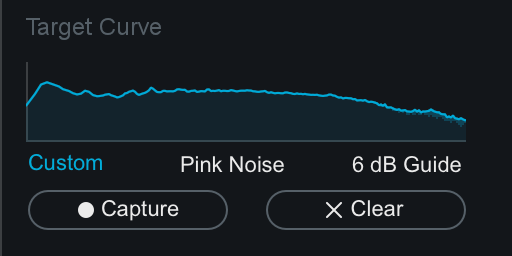
You can also choose “Pink Noise” or “6dB Guide” preset target curves instead of capturing your own.
Pink Noise & 6dB Guide Target Curves
- These snapshots represent the high-frequency decay found in many commercial recordings. You can use this as a guide to compare to your own spectrum.
- In general, many recordings follow the 6 dB slope, while some newer recordings are tending towards a brighter Pink Noise spectrum.
- You cannot adjust the overall level or position of these guides, but instead use it as a representative slope for your spectrum. It is the slope of the spectrum (as opposed to the absolute level of the mix) that defines the tonal balance.
Matched Curve Settings
After setting the Source and Target curves, you can enable the Matched EQ Curve by pressing the power button to the left of the Matching button. A white curve will appear that represents the Matched curve shape. This curve will update to based on the Amount and Smoothing settings.
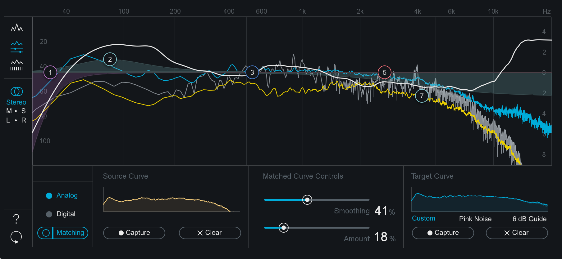
Matching eq notes
- A Matched Curve amount of 100% and a Smoothing amount of 0% might be technically the closest match to your “Reference” mix, but in reality it’s probably not the most effective combination of settings. Those settings will try to capture every peak, valley, and level, which can result in extreme, unnatural EQs.
- We suggest working with the Matched Curve amount under 50%. If your Matching EQ curve has narrow peaks and valleys, increase the Smoothing parameter to smooth them out. Your goal is to capture the overall tonal shape of the Reference as opposed to an exact match.
- Click on the Analog or Digital buttons to go back to the Main View. You’ll notice that you can still use the EQ nodes to further adjust the equalization. It may not be necessary, but feel free to further “season to taste” manually.
M/S & L/R Modes
The Equalizer module can offers Stereo, Mid/Side & Left/Right processing modes. See the Processing Mode section of the Common Module Controls chapter for more details.
Meter Scales
- EQ GAIN SCALE: Gain scale for the EQ curve is displayed on the right side of the spectrum window.
- SPECTRUM MAGNITUDE SCALE: Spectrum magnitude (dB) scale is displayed on the left side of the spectrum window.
- SPECTRUM FREQUENCY SCALE: Spectrum & EQ curve frequency scale is displayed along the top of the spectrum window.
note
- The scales for the EQ and spectrum are different, by design. If they were made to match, you wouldn’t see enough of the spectrum for it to be useful. The frequency scale in grey applies to both the EQ and the spectrum.
- You can set options for the spectrum by accessing the Spectrum Options tab or right-clicking the spectrum and selecting “Spectrum Options” from the context menu.
Alt-Solo
If you hold down the Alt key and click on the spectrum, you have an “audio magnifying glass” that lets you hear only the frequencies that are under the mouse cursor, without affecting your actual EQ settings. This is useful for pinpointing the location of a problem frequency in the mix without changing your actual EQ bands. Releasing the mouse button returns the sound to the actual EQ. You can set the default bandwidth of this filter in the EQ Options screen under “Alt-Solo Filter Q.”
Exciter
Overview
Ozone’s Exciter offers up to four bands of configurable saturation. Per band Exciter Modes give you the ability to completely customize how saturation is introduced into your music.

Per-Band Controls
The following controls are available for each band of the eggs-cider.
Amount
Controls the amount of the harmonic excitation for the associated band.
Mix
Controls the mix of the excited signal with the original mix.
Modes
The Exciter has six different modes available per band. Select modes for each band individually from the dropdown menus above the Amount and Mix sliders.
Each mode has a unique sonic character:
- ANALOG: Analog mode emulates the sound of transistor type odd harmonics giving a driven grit to your audio.
- WARM: Generates only even harmonics that decay quickly.
- RETRO: Based on characteristics of transistors, with a slowly decaying row of odd harmonics.
- TAPE: Offers a brighter sounding saturation, due to the odd harmonics found when saturating analog tape.
- TUBE: Characterized by its clear “tonal” excitation with an emphasis on dynamic or transient attacks.
- TRIODE: Accurately modeled after a tube circuit for realistic analog warmth. It uses one half of a tube circuit for a subtler overdrive than the Dual Triode mode.
- DUAL TRIODE: Models a full circuit using a vacuum tube, introducing more pronounced overdrive with a warmer tone.
Global Controls
Oversampling
This option is globally enabled or disabled for all bands of the Exciter.
Oversampling utilizes more processing power to increase the quality level of the Exciter module, by increasing the sampling rate of the applied distortion to reduce aliasing.
Link Bands
When enabled, all Mix, Amount and Mode controls in the Exciter will be linked. When link is enabled, changing the Mode in one band will update all other bands to use that Mode selection.
Adjusting the Amount or Mix controls in Link Bands mode will adjust the corresponding controls in other bands by the same amount.
Meters
Post Filter
The Post Filter allows you to adjust a high-shelf filter that affects the wet (processed) output of the Exciter module. This allows you to tame any high frequency content that may have been introduced by the Exciter processing.
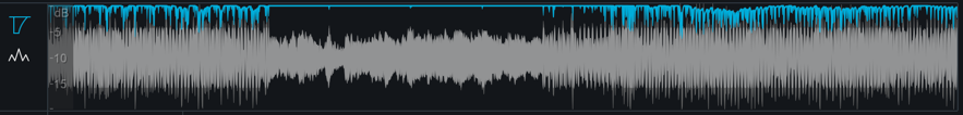
The Post Filter view also features a histogram display of the saturation being applied to your signal across the frequency spectrum. Areas of the frequency spectrum that are most affected by the Exciter will be indicated by a bright white fill, areas of the frequency spectrum that are not affected by the Exciter will not display any fill color. The histogram display is calculated after the Post Filter is applied, so adjusting the Post Filter will update the histogram display to show the saturation occurring at the output of the Exciter module.
Crossover
Displays the frequency spectrum analyzer and crossover controls for the Exciter module.
For more information on the standard multiband crossover controls in Ozone, see the Common Module Controls chapter
Imager
Overview
Ozone’s Imager module allows you to adjust the stereo width of your mix, using a multiband stereo imaging module. The Imager is also available as a component plug-in of Ozone 8 Advanced.

Controls
Band Width
Sets the amount of stereo widening applied to each band; there is one slider for each of the four bands. Positive values will widen the output of the band, negative values will narrow it (a setting of -100 is effectively mono).
Enable Stereoize
Enable Stereoize to add natural-sounding stereo width to narrow recordings.
Stereoize Amount
By adjusting the amount control in conjunction with the width sliders, you can control the character of the stereo effect. The Stereoize effect is completely mono compatible; even if you add width to audio, it can still be played back in mono without producing unpleasant artifacts.
Link Bands
When enabled, Width controls will be linked across all bands. In this case, when a Width control is adjusted in one band, the Width control will be adjusted by the same amount in all other bands.
Meters
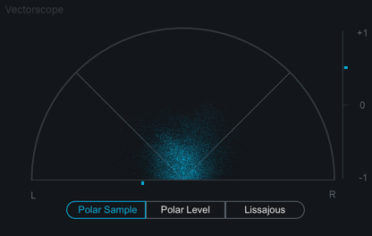
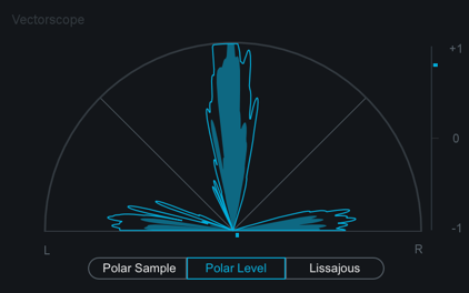
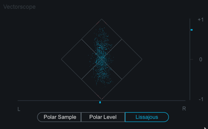
Vectorscope
The Vectorscope provides a view of the stereo image of the signal. Note that it monitors Ozone’s final output, regardless of the Imager’s place in the signal chain. You can check mixes for stereo separation, while using the module’s controls to provide more or less separation. The vectorscope provides three different views, each of which you can select by clicking on the display type label below the scope:
Polar Sample Vectorscope
The Polar Sample Vectorscope plots dots per sample, but uses a polar coordinate display that is more useful in highlighting the stereo image of the incoming signal. Patterns that appear within the 45-degree safe lines represent in-phase signals while patterns outside these lines represent out-of-phase audio. The history of the Polar Sample Vectorscope also fades out slowly. The last few seconds are displayed as slowly fading data points. You can reset the display by clicking on the meter.
Polar Level Vectorscope
The stereo energy of a recording is clearly represented by the Polar Level Vectorscope, which plots rays on a polar coordinate display that represent sample averages. The length of the rays represents amplitude while the angle of the rays represents their position in the stereo image. Rays within the 45-degree safe lines represent in-phase audio while anything beyond these lines represents audio that is out of phase. History is represented on the Polar Level Vectorscope with the shrinking of the plotted rays slowly over time. The rays shrink towards the center of the vectorscope leaving the outer portion of the display for real-time analysis.
Lissajous Vectorscope
Like the Polar Sample vectorscope, the Lissajous Vectorscope plots per-sample dots on a traditional oscilloscope display. Typically, stereo recordings produce a random pattern on a Lissajous Vectorscope that is taller than it is wide. Vertical patterns mean left and right channels are similar (approaching mono, which is a vertical line). Horizontal patterns mean the two channels are very different, which could result in mono compatibility problems.
Correlation Meter

The correlation meter indicates the degree of similarity (or correlation) between the left and right channels, displayed a +1/0/-1 vertical meter. When the audio in the left and right channels is similar, the meter draws towards the top. The extreme case is when the left and right channels are exactly the same, in which case the correlation is +1 and the meter would be positioned all the way at the top. When the left and right channels are different, the meter draws towards the bottom. The extreme case here would be for the left and right to be exactly out of phase, in which case the correlation is -1 and the meter would be positioned all the way at the bottom.
Clipping
- The Vectorscope will draw any clipped samples in red.
- You can double-click on the Vectorscope to clear the meter display.
Notes on the Phase correlation Meter
- In general, most recordings have phase correlations in the 0 to +1 region. A brief readout towards the bottom half of the meter is not necessarily a problem but could represent a possible mono compatibility issue.
- As you apply greater multiband stereo widening to your audio, the phase correlation will tend to draw more towards the bottom half of the meter, as the left and right channels will become “wider” and less similar.
Mini-meter Views
The Imager module offers different mini-meter views above the controls area.
Stereo Width Spectrum
This view shows a hybrid mirrored spectrum display of the signal’s stereo width. This meter is only available in the Imager.
Correlation Trace
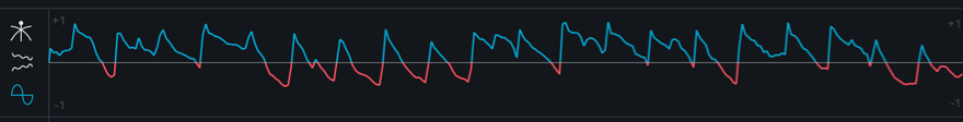
This view displays a scrolling history of the incoming signal’s stereo correlation drawn in real-time. Positive (in phase) values are drawn in light blue while negative (out of phase) values are drawn in red.
Crossover
This view displays a spectrum analyzer and multiband crossover controls. For more information about using the crossover view, see the Common Module Controls chapter.
Maximizer
Overview
Ozone’s acclaimed IRC (Intelligent Release Control) technology lets you boost the overall level of your mixes without sacrificing dynamics and clarity. The Maximizer applies to the entire bandwidth of the mix; it is not a multiband effect.
Controls

IRC Modes
The Maximizer includes the following Intelligent Release Control (IRC) modes:
IRC LL
Provides the intelligent loudness maximization of IRC I with lower latency.
IRC I
Provides intelligent digital loudness maximization of the signal. It does this by analyzing the source material and applying limiting in a psychoacoustically pleasing manner, reacting quickly to transients (to prevent pumping) and reacting more slowly to steady bass tones (to prevent distortion).
IRC II
Similar to IRC I, but optimized to preserve transients even more, so they sound sharper and clearer in the output signal, even when aggressive limiting is taking place.
IRC III
Allows for the most aggressive limiting by using an advanced psychoacoustic model to intelligently determine the speed of limiting that can be done to the incoming signal, before producing distortion that is detectable to the human ear.
The IRC III mode is very CPU-intensive, and produces a high latency, especially at higher sampling rates. You may find that at sampling rates greater than 48 kHz you are unable to use IRC III mode in real-time.
The IRC modes provide intelligent release control (the release time is automatically varied depending on the audio material). However, when the Maximizer is set to IRC III mode you may also choose between four different character “styles,” which will help you manage the limiter’s sound by constraining its release behavior.
IRC III Styles
- CLIPPING: This is the most aggressive style setting of IRC III and may be used if you wish to slightly colorize your mix with distortion or achieve the highest degree of loudness with the greatest risk of clipping.
- CRISP: This setting aggressively constrains the limiter’s release behavior and will favor distortion over any pumping.
- BALANCED: This setting constrains the release behavior of the limiter in a generally transparent way and should be suitable for most material.
- PUMPING: This is the least aggressive style setting for IRC III and does not constrain the limiter’s release behavior. It can tend toward a slower release behavior and may result in pumping. This is the “legacy” setting and is the behavior used in Ozone version 5.01 and earlier.
IRC IV
This mode builds upon our existing IRC technology by shaping the spectrum to further reduce pumping and distortion. As the signal goes farther over the threshold, the IRC IV algorithm limits frequency bands that contribute most to these peaks. This reduces intermodulation between different signal components.
For example, given vocals and drums, this algorithm can be more selective about limiting the transients from the drums, without causing the vocals to duck as much. When no limiting is necessary, the spectrum will be unaltered.
While a typical multiband limiter has only a few bands set using crossovers, Ozone’s IRC IV algorithm uses dozens of psychoacoustically spaced bands in order to react to any type of audio.
IRC IV Styles
- CLASSIC: This setting provides general enhancement of the overall mix with a sound more reminiscent of Ozone’s earlier limiting algorithms which are still being used by professionals today.
- MODERN: This style also provides general enhancement and life to your mix but with greater detail and clarity than the Classic style.
- TRANSIENT: This style is optimized for maximum preservation of all transients resulting in a highly detailed overall sound that may benefit some mixes needing added clarity.
Threshold
Determines the level at which limiting will be triggered and determines the amount of gain added to maximize the output level. Setting the Threshold to a non-zero value that doesn’t trigger the limiter will still increase the output of the Maximizer. For example, if the input level to the Maximizer is peaking at -15 dB and the Maximizer Threshold is set to -4dB, limiting will not occur, but the level at the output of the Maximizer will be peaking at -11dB.
Learn Threshold
When enabled, the Maximizer will automatically adjust the Threshold slider to in response to the input audio in order to meet the Threshold Target value defined below. Double-clicking the Target LUFS value readout allows you to edit the LUFS target.
This parameter will not disable itself after learning. It can be used to continuously update the Threshold to meet the Target value.
Learn Threshold is not recommended for loudness compliance purposes
- The Learn Threshold control is not intended to be used to meet loudness compliance standards.
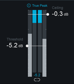
Ceiling
Determines the maximimum output level of the Maximizer. It is generally recommended to use a setting of -0.3 dB when dithering, or a more dramatic setting (-0.6 to -0.8) when mastering audio to be converted to .mp3 or .aac later, in order to prevent clipping in the future.
Threshold & Ceiling Link
When enabled, Threshold and Ceiling controls will be linked. Adjusting either control in linked mode will adjust the other control by the same amount.
True Peak
When enabled, the limiter will account for the levels of each digital sample and the levels of the analog signal that will eventually be produced by D/A conversion. Enables the limiter to take into account not only the levels of each digital sample but also the levels of the analog signal that will eventually be produced by D/A conversion. This is sometimes necessary, since an analog signal’s peak level can exceed the corresponding digital signal’s peak level by more than 3 dB.
True Peak Limiting & CPU Usage
This option will result in a small increase in CPU usage, but if your mixes are running very hot you may want to enable it to ensure that absolutely no distortion is introduced when your audio is finally run through a D/A converter.
Character
Adjust the character slider to customize the overall response time of the maximizer processing.
Stereo Independence
The Stereo Independence controls represent the next iteration of the Stereo Unlink control in previous versions of Ozone. By default, the Stereo Independence controls (Transient and Sustain) will be linked and set to 0% - mimicking the default settings of the previous Stereo Unlink control.
When limiting channels independently (with both sliders set to 100%), it is possible to achieve a louder output from the Maximizer, but this can result in a narrow stereo image. To alleviate the narrowing effect of the Stereo Unlink control, we split this feature into two sliders.
When set to non-zero values, these controls apply limiting to transient and sustained material separately, based on a level envelope generated from a ratio of the individual channel levels and the entire stereo image.
- Transient: Adjusts how the limiter responds to transient material across channels.
- Sustain: Adjusts how the limiter responds to sustained material across channels.
- Link: Links the Transient and Sustain sliders.
Transient Emphasis
Enable Transient Emphasis adjustment by clicking the Transient Emphasis power button. Adjusting the Amount control allows you to fine-tune the shaping of transients before limiting takes place. This can be useful for preserving sharper sounds, like drums, while still optimizing loudness.
Tip
- Using higher Amount values for Transient Emphasis will result in more pronounced transients after the limiting process.
Meters
Threshold Meter
The Threshold meter displays the input level to the Maximizer alongside the gain reduction applied by the Maximizer. The two meters on the far left and right of the threshold meter display the input audio level and the two meters that appear in between the input meters display the gain reduction being applied by the Maximizer.
Mini-metering Views
The Maximizer includes mini-metering views above the controls area.
Gain Reduction Trace
A scrolling meter that displays the incoming signal’s waveform with a superimposed trace that illustrates the amount of gain reduction taking place over time. The Gain Reduction Trace can help you to set attack and release controls appropriately and monitor the envelope of gain reduction.
Spectrum Analyzer
Displays the real-time spectrum of the output of Ozone.
Spectral Shaper [ADV]
Overview
The Spectral Shaper uses iZotope’s spectral shaping technology to deliver incredible high-resolution attenuation of problematic frequencies across the full spectrum. With configurable time constants, timbre adjustment, and a variable full spectrum action region - the Spectral Shaper is the perfect addition to the Ozone 8 Advanced mastering suite.
Controls

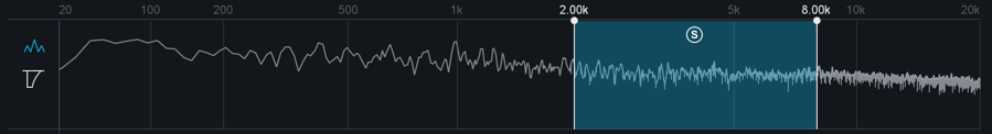
Action Region Cutoffs
The Spectral Shaper Action Region is set by adjusting the cutoff handles in the mini-spectrum meter view. The cutoff handles can be adjusted using the following methods:
- Clicking on the cutoff handles and dragging them individually
- Clicking between the cutoff handles within the meter view and dragging both cutoff handles together
- Double-clicking on the text readouts above the cutoff handles and entering a new value in the text edit box
Action Region Solo
Solos the input to the Spectral Shaper action region. This Solo occurs before Spectral Shaper processing is applied.
Mode
Sets the intensity of reduction applied by the Spectral Shaper.
- Modes include:
- Light
- Medium
- Heavy
Threshold
Sets the level at which spectral gain reduction is applied to the action region.
Listen
Solos the audio that is being reduced as a result of Spectral Shaper processing.
Tone
Controls the spectral tilt of the Spectral Shaper processing. Positive values tilt towards a brighter overall spectral character, negative values tilt towards a darker overall spectral character.
Attack
Sets the amount of time it takes for the Spectral Shaper to apply gain reduction to signals that exceed the Threshold.
Release
Sets the amount of time it takes for the Spectral Shaper to stop applying gain reduction to signals that fall below the Threshold.
Mid/Side Processing
The Spectral Shaper can operate in either Stereo or Mid/Side operation. See the Common Module Controls chapter for more information about Mid/Side Processing.
Meters
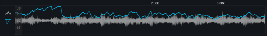
Threshold Input
Displays the highest level of all bands included in the Action Region range.
Note
- The threshold input meter in the Spectral Shaper displays different information than the threshold input meter in the Maximizer or Vintage Limiter modules. In the Maximizer and Vintage Limiter, the Threshold input level is based on the full frequency spectrum. The Spectral Shaper Threshold input level is based on the highest level of the frequency bands included within the action region.
Mini-Meter Views
Action Region
Displays the Action region cutoff handles and Action Region Solo controls on top of a spectrum meter.
Gain Reduction Trace
A scrolling meter that displays the incoming signal’s waveform with a superimposed trace that illustrates the amount of gain reduction taking place over time. The Gain Reduction Trace can help you to set attack and release controls appropriately and monitor the envelope of gain reduction.
Vintage Compressor [ADV]
Overview
Think of the Vintage Compressor as an accurate analog emulation of a compressor that has never existed before! We’ve combined some of the best elements of vintage analog compressors to create this algorithm.
The Vintage Compressor is a feedback compressor. A compressor detects the signal level, and reduces the gain when the signal goes above the threshold. In a feedback compressor, the level detection is done on the output of the compressor, as opposed to the input. This design is common for older analog compressors, but very uncommon for digital compressors, which usually use a feedforward topology. Feedback compression is natural for analog circuits, but diffcult to implement digitally. Due to the feedback, the output of the compressor instantaneously depends on itself, which computers are not well suited to resolve. Our algorithm uses some sophisticated techniques to solve this, avoiding a fictitious delay in the feedback loop, for an extremely accurate analog emulation.
The attack and release ballistics are an important part of a compressor’s sound. The release is program-dependent, meaning that the release time on transients is much faster than it is on periods of sustained compression, which helps to decrease both pumping and distortion. Another unique feature of feedback compressors is that the attack and release times can vary depending on how much compression is occurring.
This algorithm includes a versatile detection filter in the feedback loop. This filters the signal that is passed into the level detector to change which components of the signal are triggering the compressor. Some compressors use a highpass filter or a high shelf boost to reduce pumping. Others have a wide boost in the high frequencies to let high frequency content drive the compressor. The Vintage Compressor in Ozone includes all of these filters.
Controls

Threshold
Adjust the threshold of the compressor to set the point where the dynamics processing takes place. Since some modes have a soft knee, mild compression may occur below this point too.
Ratio
Sets the amount of attenuation to be applied to the signal once it has passed the threshold. Higher ratios will result in more extreme compression.
Attack & Release
Adjust the attack and release controls to set how quickly the Vintage Compressor reacts to audio that crosses the threshold.
- ATTACK: Determines how quickly the Vintage Compressor reacts when the threshold is reached.
- RELEASE: Determines the amount of time before the Vintage Compressor returns the level to normal once the signal is no longer above the threshold. This control sets the release time for transients; for sustained compression, the release time will be significantly longer.
Mode
The Mode selector adjusts the signal-dependent, internal ballistics of the Vintage Compressor and consequently changes its overall sonic character to suit the type of sound you’re looking for. The Vintage Compressor includes the following modes:
- SHARP: Provides crisp dynamics and a greater emphasis on transients while the body of the signal is kept under control.
- BALANCED: Gives a signal-dependent balance between dynamics preservation and overall enhancement to the body of the signal.
- SMOOTH: Aptly named, Smooth mode smoothes out transient and dynamic material but enhances and brings out the rest of the signal leading to a thicker and fuller sound.
Gain
The gain slider adjusts the output gain of the Vintage Compressor module. This is useful, for example, after compressing to makeup the decrease in volume.
Auto Gain
When you click the Auto button, automatic gain control calculates the RMS levels of both the input and output signals of the Vintage Compressor, and then applies the appropriate gain to the output signal to compensate for the difference.
This automatically brings audio levels to a level comparable to the unprocessed audio, and acts as a smart “make-up gain” control that adapts to the mix over time. This is also a useful tool for A/B’ing various settings without having gain changes affect your perception.
Mid/Side Processing
The Vintage Compressor module can operate in either Stereo or Mid/Side operation. See the Common Module Controls chapter for more information about Mid/Side Processing.
Meters
Threshold Meter
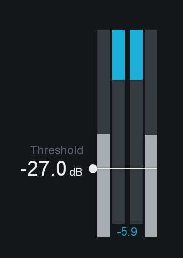
The Threshold meter displays the input level to the module alongside the gain reduction applied by the module’s processing. The two meters on the far left and right of the threshold meter display the input audio level and the two meters that appear in between the input meters display the gain reduction being applied.
Mini-meter Views
Detection Filter
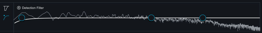
This view allows you to adjust the frequency response of the detection circuit used by the Vintage Compressor, so that it is more or less sensitive to specific frequencies. You can adjust the input to the Detection Filter by modifying the filter nodes that appear in this view.
To listen to the filtered input to the detection circuit, click the “Solo Detection Filter” button in the upper left corner of the Detection Filter view. This is useful for quickly listening to the input signal being used to trigger the Vintage Compressor processing.
Gain Reduction Trace
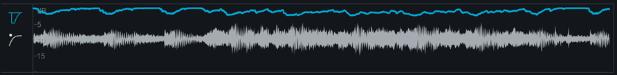
This view offers a scrolling meter that displays the incoming signal’s waveform with a superimposed curve that illustrates the amount of gain reduction taking place in real time. The Gain Reduction Trace can help you to set attack and release controls appropriately and monitor the envelope of gain reduction.
Vintage EQ [ADV]
Overview
The Vintage EQ module is based on the Pultec EQP-1A and Pultec MEQ-5, two highly regarded equalizers from the 1950s. EQP-1A affects the high and low frequencies, and MEQ-5 affects midrange frequencies. The Ozone Vintage EQ closely emulates the frequency response of the Pultec EQP-1A and MEQ-5 by modeling their individual circuit components.
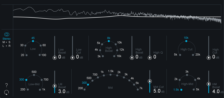
Low & High Frequency Controls
The top row of parameters in the Vintage EQ module are modeled after the Pultec EQP-1A Equalizer.

A unique feature of the Pultec EQP-1A is the ability to simultaneously adjust the boost and cut parameters for the low frequency band. While the original manual warns “Do not attempt to boost and attenuate simultaneously,” these controls interact in a way that many engineers have found to be extremely desirable. Rather than canceling each other out, combining these controls results in a boost in the low frequencies, followed by a dip slightly higher up. This unique filter shape is also available in the Ozone Equalizer module as the “Vintage Low Shelf”.
Low Frequency Controls
- LOW FREQUENCY: Sets the low frequency to be boosted. Options include: 20 Hz, 30 Hz, 45 Hz, 60 Hz, and 100 Hz.
- LOW BOOST: Sets the amount of boost applied to the selected low frequency. This is a low shelf filter.
- LOW CUT: Sets the amount of attenuation applied to the selected low frequency. This is also a low shelf filter.
Low Frequency Selection Note
- The 45 Hz option isn’t present in the original hardware unit, but we’ve added this frequency because we found it to be useful for mastering.
High Frequency Boost Controls
- HIGH BOOST FREQUENCY: Sets the high frequency to be boosted. Options include 3 kHz, 4 kHz, 5 kHz, 8 kHz, 10 kHz, 12 kHz, and 16 kHz.
- HIGH BOOST: Sets the amount of boost applied to the selected high frequency. This is a peaking filter.
- HIGH Q: Sets the bandwidth for high frequency boosting. The boost amount and bandwidth interact (i.e., the Q changes as you boost), as they do in the EQP-1A.
High Frequency Cut Controls
- HIGH CUT FREQUENCY: Sets the high frequency to be attenuated. Options include 5 kHz, 10 kHz, and 20kHz.
- HIGH CUT: Sets the amount of attenuation applied to the selected high frequency. This is a high shelf filter.
Mid Frequency Controls
The bottom row of parameters in the Vintage EQ module are modeled after the Pultec MEQ-5 Equalizer.
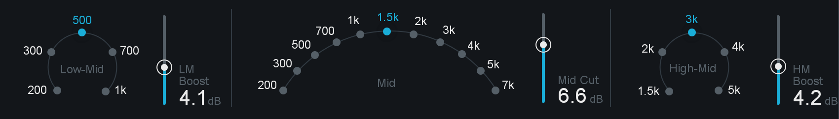
All of the mid frequency controls are peaking filters. As in the original MEQ-5, the filter bandwidths are affected by the boost/cut amount.
Low-Mid Frequency Controls
- LOW-MID BOOST FREQUENCY: Sets the low-mid frequency to be boosted. Options include 200 Hz, 300 Hz, 500 Hz, 700 Hz, and 1000 Hz.
- LM BOOST: Sets the amount of boost applied to the selected low-mid frequency band.
Mid Frequency Cut Controls
- MID CUT FREQUENCY: Sets the mid frequency to be attenuated. Options include 200 Hz, 300 Hz, 500 Hz, 700 Hz, 1 kHz, 1.5 kHz, 2 kHz, 3 kHz, 4 kHz, 5 kHz, and 7 kHz.
- MID CUT: Sets the amount of attenuation applied to the selected mid frequency.
High-Mid Frequency Fontrols
- HIGH-MID BOOST FREQUENCY: Sets the high-mid frequency to be boosted. Options include 1.5 kHz, 2 kHz, 3 kHz, 4 kHz, and 5 kHz.
- HM BOOST: Sets the amount of boost applied to the selected high-mid frequency.
M/S & L/R Controls
The Vintage Compressor offers Stereo, Mid/Side or Left/Right processing modes. See the Common Module Controls chapter for more information about Mid/Side & Left/Right processing modes.
Meters
Spectrum Analyzer & Composite EQ Curve
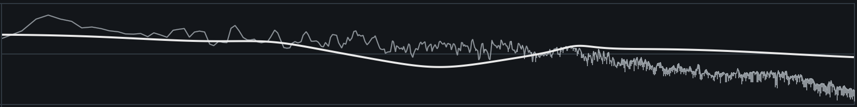
Displays the composite EQ curve of your current Vintage EQ settings over a real-time spectrum analyzer that shows Ozone’s output signal.
Vintage Limiter
Overview
The Vintage Limiter allows you to create a louder and fuller master by limiting the dynamic range and boosting the overall level of your mix. It is loosely modeled after the Fairchild 670, a feedback-based tube compressor/ limiter with a soft knee, with slightly different attack and release envelopes due to a differing feedback topology. An IRC I limiter is then applied after the tube processing to transparently prevent clipping. Like the Maximizer, the Vintage Limiter is applied to the entire bandwidth of the mix; it is not a multiband effect. The Vintage Limiter represents the best of both worlds by providing a warmer, more analog-sounding final-stage of limiting while retaining the ease and precision of digital maximizing.
Controls

Modes
Three separate limiting modes are available, each with unique characteristics and sounds:
- ANALOG: With a fast attack and variable release time, this mode provides a tight bass response with a “thick” limiting quality. This brings out the low-end transients while still providing the smoothness that is characteristic of analog circuitry.
- TUBE: A more balanced limiter with variable attack and release times, this mode provides smooth feedback limiting with a wider range of sonic characteristics that vary depending on your incoming signal. Despite its non-linearity, it still allows for modern precision in preventing any clipping or peaks.
- MODERN: A true hybrid of old and new, this mode blends thicker vintage characteristics and wide range of non-linearity with modern IRC limiting, variable release times, and transient reproduction.
Threshold
The Threshold control determines the level at which the Vintage Limiter will begin limiting. When the incoming signal level crosses above the threshold value, the limiter kicks in. This control also adds gain as the threshold value is lowered. Turning down the threshold limits more of the signal, which in turn creates an overall louder mix.
In other words, when you turn down the threshold you limit the dynamic range of the mix, the Vintage Limiter will automatically add a proportional amount of gain to maximize the output level.
Ceiling
The Ceiling control sets the maximum output level of the Vintage Limiter.
Recommendation
It is generally recommended to use a setting of -0.3 dB when dithering, or a more dramatic setting (-0.6 dB to -0.8 dB) when converting to MP3 or AAC formats in order to prevent clipping during conversion. See the Codec Preview section for more details.
Link Threshold & Ceiling
When enabled, Threshold and Ceiling controls will be linked. Adjusting either control in linked mode will adjust the other control by the same amount.
True Peak Limiting
The True Peak Limiting control enables the limiter to take into account not only the levels of each digital sample but also the levels of the analog signal that will eventually be produced by D/A conversion. This is sometimes necessary, since an analog signal’s peak level can exceed its corresponding digital signal’s peak level by more than 3 dB.
True Peak Limiting & CPU Usage
This option will result in a small increase in CPU usage, but if your mixes are running very hot you may want to enable it to ensure that absolutely no distortion is introduced when your audio is finally run through a D/A converter.
Character
The Character control adjusts the attack and release times of the Vintage Limiter. It employs different attack and release times depending on the mode that is selected, but allows a continuous range from Fast (0.0) to Slow (10.0) in each mode.
Meters
Threshold Meter
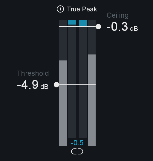
The Threshold meter displays the input level to the module alongside the gain reduction applied by the module’s processing. The two meters on the far left and right of the threshold meter display the input audio level and the two meters that appear in between the input meters display the gain reduction being applied.
Mini-Meter Views
Gain Reduction Trace
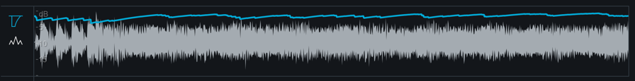
This view offers a scrolling meter that displays the incoming signal’s waveform with a superimposed curve that illustrates the amount of gain reduction taking place in real time. The Gain Reduction Trace can help you to set attack and release controls appropriately and monitor the envelope of gain reduction.
Spectrum Analyzer
Displays a real-time spectrum analyzer of the output of Ozone.
Vintage Tape [ADV]
Overview
Vintage Tape provides the frequency response (magnitude plus phase) and saturation characteristics of magnetic tape without the crosstalk, hiss, wow, and flutter that might ruin your mix. It’s inspired by a well-maintained Studer A810 two-track tape deck, a clean and accurate machine perfect for mastering. The amount of tape saturation depends heavily on a very high frequency (~100 kHz) AC bias signal, and changing the level of bias can dramatically change the character of the saturation effect. A high bias reduces dynamic range providing more compression, a low bias also adds distortion but in a different manner. Tape-saturation is a wavelength (tape speed divided by frequency) dependent process so the exact sound of the saturation is a complex interplay between tape speed, bias-level, program material and other factors. Tape saturation typically produces distortion with odd harmonics. However, inaccuracies in the AC bias design or distortion from machine electronics often mixed in even harmonics. Vintage Tape allows you to customize the amount of even harmonic distortion and the “lumpiness” of the reproduction head frequency response if you want to undo some of the engineering work that made tape quite transparent for an analog medium.
Controls

Input Gain
Changes the gain of the input signal prior to tape emulation. Tape becomes non-linear when recording high amplitude signals, leading to saturation. Increasing the input gain prior to tape emulation can lead to more saturation, while lowering the input gain decreases saturation. The level necessary to achieve a certain amount of saturation depends on the frequency content of the source material and the bias setting.
Vintage tape also contains internal automatic gain adjustment, which uses the value of the input gain and knowledge of the tape saturation process to avoid large jumps in output level, whatever the amount of input gain you apply.
Bias
Bias primarily impacts the the shape of the distortion curve, but also changes the frequency response (mainly the high end). Negative bias boosts high frequencies, and causes more high frequency distortion than positive bias. High values of positive bias can severely limit dynamic-range, a characteristic of over-biased tape machines.
Speed
Speed primarily changes the frequency response, but also changes the level where different frequencies experience distortion. Specifically high frequencies (small wavelengths) distort at lower input levels than low frequencies (long wavelengths). Changing the speed changes the wavelength (wavelength=speed/frequency), so a 500Hz signal at 7.5 ips will experience distortion at the same level as a 1kHz signal at 15 ips and a 2kHz signal at 30 ips.
Harmonics
Adds even harmonics into the tape distortion.
Low Emphasis
Controls the resonant peak of the reproduce tape head bump. Increasing this control will add gain to bass heavy material.
High Emphasis
Compensates for high-frequency losses in the reproduce tape head.
Meters
Spectrum Analyzer
Displays a real-time spectrum analyzer of the output of Ozone.
Codec Preview [ADV]
Overview
When converting to a lossy audio format (such as MP3 or AAC), psychoacoustic algorithms are used to truncate the less audible components of your audio. This means that parts of your audio are actually being removed, which has a subtle (or obvious, at lower bit rates) affect on the sound.
Codec Preview allows you to hear what your master will sound like after lossy audio compression has taken place, and gives you the opportunity to compensate for this data loss without leaving your DAW. For example, when converting to a low bit rate MP3, you may want to brighten your audio slightly, to counteract the loss of high frequency data.
Accessing the Codec Preview Panel

The Codec Preview panel can be accessed by clicking the “Codec” button in the Auditioning section of the Ozone application and the main Ozone 8 plug-in.
Codec Preview Availability
- Note that Codec Preview is an Advanced only feature and is not available in the component plug-ins. You can access Codec Preview in the main Ozone plug-in and Ozone application.
Enable/Disable Codec Preview

Click the power button next to the “Codec” button in the auditioning area to enable or disable Codec Preview processing.
Controls
The following controls appear in the Codec Preview panel:
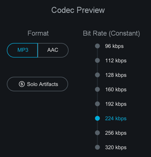
Format: MP3/AAC
Select the codec format to preview: MP3 or AAC.
Ozone Codec Information
- AAC: Ozone uses the Fraunhofer AAC codec.
- MP3: Ozone uses the LAME codec www.mp3dev.org.
Bit Rate (Constant)
Sets the constant bit rate value used by Codec Preview.
| Bit Rate | Notes |
|---|---|
| 96 kpbs | Generally used for low quality streaming |
| 112 kbps | |
| 128 kbps | |
| 160 kbps | |
| 192 kbps | |
| 224 kbps | |
| 256 kbps | For Mono Files 256 kbps is the highest supported bit rate in Codec Preview. |
| 320 kbps | Highest bit rate supported by MP3 |
Solo Codec Artifacts
This option lets you hear what is being lost in the codec conversion. The codec artifact signal is the codec preview signal subtracted from the unencoded signal.
Sample Rates & Performance
Performance Note
AAC and MP3 files don’t support sample rates greater than 48kHz. In order to accurately represent the sound quality changes introduced by AAC and MP3 compression, it may be necessary for real- time resampling to take place when Codec Preview is enabled. If your session sample rate is set to a value other than 44.1kHz or 48kHz, Ozone will perform high-quality real-time resampling when Codec Preview is in use. Real-time resampling uses a lot of CPU, most noticeably within high sample rate sessions that utilize small buffer sizes. To avoid any discontinuities or performance issues when using this feature within high sample rate sessions, we recommend adjusting the buffer size to a larger value.
Additionally, real time resampling is mathematically intensive and may incur significant latency. Most hosts should be able to compensate for this latency, but you may notice a slight delay in playback when Codec Preview is enabled.
Signal Flow
Codec Preview is at the very end of the signal chain within Ozone. When you are using Ozone as a plug-in, it is important that Ozone is placed after all other inserts if you are using Codec Preview. This will ensure that the signal going into Codec Preview includes all of the processing being applied to the mix.
Codec Preview is intended to be used for previewing only and will not apply actual MP3 or AAC compression when exporting from the Ozone application or a DAW. You can use the Codec Preview feature to help inform the export settings of your host application, but be sure to disable the feature prior to exporting.
Headroom & Clipping
Any lossy encoder introduces an approximation error, a noise which can increase peak levels and cause clipping in an audio signal, even if the uncompressed source audio file appears to peak under 0 dB.
When mastering for compressed audio formats like AAC and MP3, it’s a good idea to leave between -1 dB and -1.5 dB of headroom to prevent clipping due to file compression.
Codec Preview can help you tailor your processing to avoid clipping that might occur as an artifact of lossy codecs.
The clip indicators above the Ozone output meters will help inform you of clipping caused by a codec before you export your audio.
Dither
Overview
Ozone contains a comprehensive set of dithering tools that allows you to prepare studio-quality audio for CD and other formats by effectively converting and dithering audio to 24, 20, 16, 12, or 8 bits. Note that Dither processing is independent of the Maximizer module.
Key Features
- Includes iZotope MBIT+ Dither for exceptionally transparent conversion to dfferent bit depths. This is a proprietary iZotope word length reduction technology that reduces quantization distortion with minimal perceived noise. While this might sound like a paradox, MBIT+ is a very smooth, quiet, and almost “analog sounding” technology.
- Unique set of bit meters and DC offset (direct current offset) meters provides a complete view of the digital bitstream and conversion process.
View/Enable Dither panel

- Access the Dither panel by clicking on the Dither button below the I/O meters.
- Enable or disable Dither by clicking the power button to the left of the Dither button.
Controls
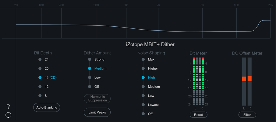
Bit Depth
Sets the target bit depth for the audio. When mastering for a CD, for example, you would want this set to 16 bit.
Note: 8 & 12 Bit Options
- The 8 & 12 bit options in the Dither panel are preview only in the Ozone application, you cannot use 8 or 12 bit Dither when exporting from the Ozone application.
Dither Amount
Sets the number of bits or amount of dither that will be used. Dither Amount options include:
- Strong
- Medium
- Low
- Off
Note about Dither Amount options
- Off & Low options can leave some non-linear quantization distortion or dither noise modulation.
- The Strong option completely eliminates the non-linear distortion issues that may result from using Off or Low, but this comes at the expense of a slightly increased noise floor.
- In general, Medium is the recommended choice for the Dither Amount setting.
Harmonic Suppression
If for some reason any dithering noise is undesirable, simple truncation remains the only option. Truncation results in harmonic quantization distortion that adds overtones to the signal and distorts the timbre.
In this case, you can click the Harmonic Suppression button to slightly alter the truncation rules, moving the harmonic quantization distortion away from overtones of audible frequencies.
This option doesn’t create any random dithering noise floor. Instead it works more like truncation, but with better tonal quality in the resulting signal.
Limit Peaks
Dither noise is random in nature and has a very low amplitude, so dither peaks are not often a problem. However, depending on your dithering settings (especially when using more aggressive dithering modes) the high frequency dither noise can be amplified significantly after noise shaping. This can result in spurious peaks in the overall dither signal (up to -60 dBFS for 16-bit quantization).
When enabled, the Limit Peaks control allows you to effectively suppress the spurious peaks caused by aggressive dither settings.
Auto-Blanking
Selecting this option will completely mute dither output (i.e. dither noise) when the input signal is completely silent (0 bits of audio) for at least 0.7 seconds.
Noise Shaping
Selects the amount of noise shaping that is applied during the dithering process. Noise shaping pushes the noise necessary for dithering into less audible frequency ranges, allowing for greater dithering with less perceived noise.
You can control the aggressiveness of this shaping, ranging from Off (no shaping) through Max (roughly 14 dB of audible noise suppression).
Different amounts of noise shaping will have subtle effects on the sound quality of the dither process, so experiment with the di erent settings with your particular program material.
Filter DC Offset
Activates a high-pass filter with a 1 Hz cutoff frequency.
DC offset (direct current offset) is a defect in the recording when the waveform’s average voltage is above or below zero. Audio signals are normally represented by an alternating current whose average value is zero. Some malfunctions in the recording equipment can result in a direct current leaking into the signal. Thus, the recorded waveform appears to be above or below the zero line.
In FFT (Fast Fourier Transform) analyzers, the DC offset is represented with energy at zero frequency (0 Hz). A DC offset can be removed with a high-pass filter. It is important to distinguish DC offset from waveform asymmetry. Asymmetry skews the waveform shape towards positive or negative levels, but the average current stays at zero. Unlike DC offset, asymmetry has no particular energy near 0 Hz and can be reduced using phase rotation filters.
Note
The DC Offset Filter runs in real-time before the Maximizer. The Maximizer module must be in signal chain to enable DC offset filtering.
Meters
Bit Meter
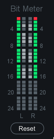
This can be an invaluable resource for monitoring the digital activity of your program material, including viewing:
- Whether the full range of bits (dynamic range) is being used.
- The output word length.
- Faulty A/D converters.
- Sub-par plug-in processing (detecting a plug-in that’s only processing at 16 bit, using fixed integer math, etc.).
The bit meter monitors the state of bits in a digital signal.
- The inner two columns show the real-time activity of the bits of audio, for the left and right channels.
- The outer two columns remember the real-time activity in a sort of “peak hold” way.
- If the inner columns toggle a bit (i.e. “light up”) the outer columns will show that bit as being used.
In general, you want to see activity on each of the bits (except the top one, see below for explanation), meaning that over a period of a few seconds each of the bits in the outside columns should be lit.
You should also click on the meter periodically to reset the peak hold of the outside columns, as something like DC offset would toggle a lower bit once (lighting the outside column), but would never toggle it after that since the bit is being held.
If you’re dithering down, you only want to see 16, 12, or 8 bits lit (corresponding to the output bit depth of the dither).
Note that the bit meter is not a level meter. Instead, it shows which bits are being used. If a bit is used (goes from 1 to 0 or vice versa), the position for that bit is lit. The main use of the bit meter is to look for problems or discontinuities in the digital signal.
Some examples of problems you can identify with a bit meter are:
- HEADROOM: You may have a 24 bit audio file, but aren’t using all of the bits.
- 16 BITS: In a more extreme case, you are only using 16 bits. If you’re dithering to 16 bits, this is what you want to see. However, if you’re not dithering, this would suggest there is a problem somewhere, either an A/D converter that is only putting out 16 bits, a plug-in that’s truncating the signal down to 16 bits, etc.
- STUCK BIT: One bit in the middle of the signal isn’t being exercised, possibly due to a faulty A/D converter or bug with a software plug-in.
Why the Top Bit Will Never Light Up in the Bit Meter
- When samples are stored as a binary number, negative samples are specially encoded. Since the binary representation of negative numbers is not intuitive, Ozone takes the absolute value of each sample before plotting it on the bit meter.
- Since the most significant bit is only set when a sample is negative, this bit will never light up. We simply included the top bit as placeholder for completeness.
Bit Meter Reset
Click here to reset the bit meter and start its display over with the program material’s current playback point.
Noise Shaping Curve
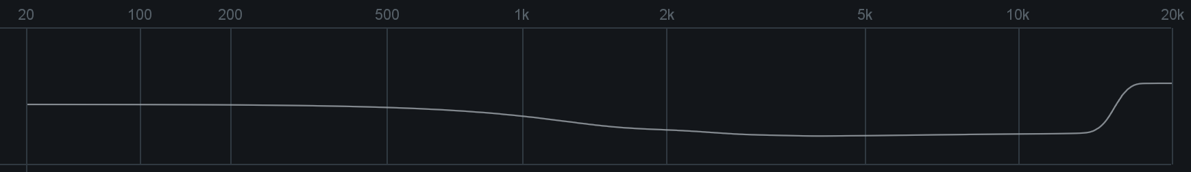
This graph shows the noise-shaping profile curve, as displayed across the frequency spectrum. The graph displays the general frequency curve of the specific dither noise profile that is used, depending on the algorithm.
DC Offset Meter
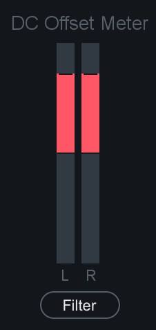
When the DC Offset Filter is on, the DC Offset meter shows the amount of the DC that is being removed.
More information about Dithering
- If you are interested in getting some practical tips for using dithering, as well as some of the theory behind it, please check out the Educational Guides on the iZotope website.
- Check out the Tips & Examples chapter for some Dithering tips.
Master Assistant
Overview
Master Assistant is the latest advancement in assistive technology, machine learning, and intelligence in Ozone 8 Elements, Standard, and Advanced. It is designed to give you a starting point that is intelligently tailored to your music to help you create a professional sounding master regardless of your experience level.
Master Assistant is included in the main Ozone 8 plug-in and Ozone 8 standalone application. The Master Assistant panel can be opened by clicking the “Master Assistant” button to the left of the preset display.
Genre Classes & Research Findings
Master Assistant utilizes target genre curves that were born from a mixture of internal discussion and research. We started by grouping a large variety of audio files into ten classes of musical genre. These genre classes were then analyzed for their spectral characteristics. Based on our research, we created ten genre target curves that represent the typical spectral characteristics for each genre class.
In addition to analyzing typical spectral characteristics, we also trained a neural net classifier to map incoming audio to a unique target curve that represents a mixture of the 10 genre classes.
Note: Though we are categorizing into 10 different genres, our research has shown that most curves fall within three broad categories. We included combination target curves that represent these three broad categories with the Tonal Balance Control plug-in.
These three representative categories are:
- Bass Heavy (EDM, Hip/Hop, etc.)
- Orchestral (Broad instrumental, etc.)
- Modern (Pop, Rock, etc.)
See the Processing Steps section below for more information on how these curves are used during Master Assistant processing.
Workflow
Master Assistant is available in the main Ozone 8 plug-in and the Ozone 8 application. You can open the Master Assistant panel by clicking on the “Master Assistant” button to the left of the preset display.

Target Selection
Before running Master Assistant, select your Target output in the first screen that appears.
Streaming

- Informs the Maximizer Threshold in order to meet a loudness target value (in LUFS).
- The Streaming option will set the target loudness to -14 LUFS by default. This target value is based on the typical loudness value used by popular streaming services.
- This value can also be customized in the General tab of the Ozone Options menu.
CD
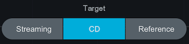
Informs the Maximizer Threshold setting in order to achieve the loudest possible output for the selected Intensity option.
CD: Intensity

Informs the Maximizer Threshold value by specifying how often the limiter will be triggered by the incoming audio.
Reference
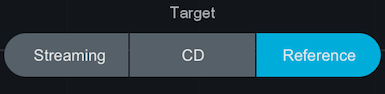
- Allows you to choose any reference track that is currently loaded in the Reference panel as your target.
- When this option is selected, the target loudness and target EQ curves will be calculated from the loudness and EQ curve of the selected reference track.
These Target choices influence the analysis and results of Master Assistant in different ways. The steps below explain how the Target selection affects a given processing step.
Playback Audio
After selecting a target, hit Next to run Master Assistant.

Useful Tips
- Master Assistant needs audio input: Make sure you are playing back audio in the Ozone 8 application and/or your host application.
- For best results, we recommend running Master Assistant on the loudest portion of the track.
- Master Assistant needs approximately 30 seconds of audio during analysis. If you want Master Assistant to analyze a section that is less than 30 seconds long, we recommend looping playback prior to running Master Assistant.
Notes about Reference Target selection
- You need to have a Reference track loaded in the Reference panel in order to run Master Assistant with Reference selected as the target. You will need to exit Master Assistant and load a reference file in order to proceed.
- Note that Reference files need to finish loading completely before being available to select in the Master Assistant Reference track dropdown menu.
Processing Steps
Below is an outline of the steps Master Assistant works through after making a target selection and clicking on the ‘Next’ button.
Analyze Audio
After clicking the “Next” button Master Assistant will listen to the incoming audio for roughly 5 seconds.
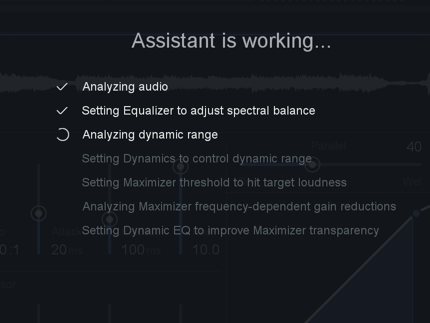
Waiting For Audio screen
If Master Assistant is not receiving audio a “Waiting for audio” screen will appear. To dismiss the Waiting screen, simply playback audio.
Generate Unique Target Curve
After listening to your audio for a few seconds, Master Assistant will generate a unique target curve to use in the EQ processing step (explained below).
How does master assistant generate unique target curves?
- During the initial listening pass, Master Assistant will analyze your audio and determine how similar it is to the 10 predetermined genre class curves (these curves are explained in the Genre Classes section above).
- A percentage of similarity is assigned to each genre class curve.
- Master Assistant will then create a unique target curve that is based on the genre class percentages detected in your audio.
- For example: if Master Assistant classifies your track with the following percentages: 60% Pop, 30% Rock, and 10% Country. The resulting unique target curve will be a mix of 60% of the Pop target, 30% of the Rock target and 10% of the Country target.
Target curve is based on Reference audio
- When “Reference” is chosen as the Master Assistant Target, the unique target curve is derived from the selected Reference track and not by calculating the genre classes of your input audio.
Apply Preset
After generating a unique target curve, Master Assistant will load a preset that is based on the genre class we detected with the highest percentage of similarity. These presets are used to provide starting points for the modules utilized in Master Assistant processing and will set parameters that are not learned from your input audio, such as: IRC Mode in the Maximizer, Attack & Release times in Dynamics, etc. The Master Assistant presets are more subtle than the presets used in Neutron’s Track Assistant processing.
Module chain contents after running Master Assistant
- The modules included and their order in the signal chain will always be the same after running Master Assistant.
- In some circumstances (depending on your input audio) Master Assistant will bypass the Dynamics module. Keep reading the steps below for more information on how this decision is made.
- To reiterate: The modules in the signal chain after running Master Assistant are meant to function as a suggestion or starting point for your master. Ozone has a wealth of processing modules available and we encourage you to add or remove modules to suit your track.
EQ
After applying a preset, Master Assistant will modify the settings in the EQ module.
Master Assistant will intelligently modify the EQ settings by comparing the input audio to the unique target curve generated in the first processing step. EQ nodes are adjusted with the goal of modifying the EQ curve to more closely match your incoming audio to the unique target curve.
EQ band settings
- Master Assistant will always enable Low Shelf & High Shelf filters on Bands 1 & 8 (respectively).
- Master Assistant will add up to 6 Peak Bell filters in Bands 2-7 in order to match the target curve.
Dynamics
After setting the EQ module, Master Assistant will modify the settings of the Dynamics module. Applying some light low-end compression to overly dynamic audio will allow the Maximizer to operate more transparently. Master Assistant measures the Crest Factor of your incoming audio in order to determine if applying Dynamics processing will positively affect the output of the Maximizer.
If the detected genre class falls under the broad “Orchestral” category, crest factor will be calculated based on the full bandwidth of your signal. Otherwise, Crest Factor will be calculated for the low band of your input audio.
If the Crest Factor measurement is higher than a predetermined cutoff value (this cutoff was determined as a result of our internal research) we will enable the Dynamics module. If the Crest Factor measurement falls under our pre-determined cutoff value, the Dynamics module will be disabled.
What is Crest Factor?
Crest Factor is a measurement of peak amplitude value divided by the RMS value of a waveform. This measurement is used to indicate how extreme peaks are in a given waveform, which can be equated to the dynamic range of a signal. The total Crest Factor range used by Master Assistant is -1 to 14 and the “ideal” Crest Factor range is 3 to 10. If the Crest Factor measurement is lower than 3, it can be considered “too compressed.” If the Crest Factor measurement is higher than 10, it can be considered “too dynamic.”
The Compressor threshold values are learned based on the average level of your input audio to ensure that the Compressor is affecting your audio.
Maximizer
After setting the Dynamics module, Master Assistant will move on to adjusting the settings in the Maximizer.
Ceiling
The Ceiling value is set based on the Target selection you made in the first screen of Master Assistant.
- Streaming: -1dB
- CD (for all Intensity values): -0.3dB
- Reference: -0.3dB
Threshold
The Threshold value is set based on your input audio and the learning behavior defined by your Master Assistant Target selection.
Streaming
- Target loudness value for the Maximizer Threshold is set to -14 LUFS (common loudness for popular streaming services)
- Loudness Target can be manually set in the Options > General tab
CD
- Sets the Maximizer Threshold to give you the loudest possible master based on your input audio and Intensity selection.
CD: Intensity
Determines how often the Limiter should be engaged when learning the Maximizer Threshold.
- Low: Limiter is engaged 0% of the time
- Medium: Limiter is engaged 1% of the time
- High: Limiter is engaged 2% of the time
Reference
- Target loudness value (in LUFS) for the Maximizer Threshold is calculated from the loudness of the selected reference track.
Note
- If your track is louder than the Target Loudness value, Master Assistant will not make it any quieter than the difference introduced by the Ceiling value.
Important Note
It is important to play the loudest portion of your track when running Master Assistant. Learning the Maximizer Threshold on a quiet portion will maximize the loudness for that portion of the track. This has the potential to introduce distortion in louder sections of the track because the Threshold was learned for lower level signals.
Dynamic EQ
Master Assistant will compare the input and output signals of the Maximizer to determine which frequencies are hitting the Limiter the hardest.
Dynamic EQ nodes are placed at peak frequencies to reduce potential distortion introduced by the Maximizer. The Threshold values are learned based on the input audio to the Dynamic EQ bands.
Accept/Cancel
When Master Assistant has finished, you can Accept or Cancel the changes.
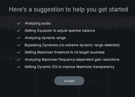
- Accept will dismiss the Master Assistant panel and retain all settings modified by Master Assistant.
- If you Accept changes and decide to revert them, you can undo Master Assistant changes in the Undo History window.
- Cancel will dismiss the Master Assistant panel and revert your settings to the state they were in prior to running Master Assistant.
Track Referencing
Overview
Track Referencing in Ozone 8 is the definitive workflow for helping you compare and contrast music in your DAW. Using the new Reference Panel in Ozone, you can import up to 10 reference tracks, visualize differences in your music with overlaid spectrum metering, and quickly A/B your music right from the audition panel.

Importing References
The Reference panel is accessible by clicking on the “Reference” button in the lower right hand corner of the Ozone interface. You can add up to 10 Reference files in the Ozone 8 application and Ozone 8 main plug-in.
Click on the “+” button in the middle of the empty Reference panel to select a reference files to load.
Supported File Formats
| Supported file formats |
|---|
| wav |
| aif/aiff |
| mp3 |
| AAC |
| FLAC |
The Reference panel supports loading up to 10 reference tracks at a time. When using the Reference panel in the Ozone application, the loaded references will be shared across different tracks (i.e. Each track in a given Ozone project will display the same 10 reference tracks in the Reference panel.)
Loop Segments
When tracks are initially loaded into the Reference panel, handles will appear overlaid on the waveform display. The handles represent boundaries of predetermined loop points. The loop boundaries are placed based on similar segments detected in the track, this uses the same machine learning technology used to generate the segmentation bar under waveforms in the Ozone application.
By default, the segments will be named with a letter. (A/B/C/D/E)
RENAME LOOP SEGMENTS
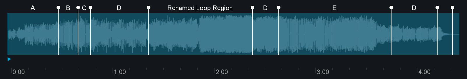
To rename a loop segment in the Reference panel:
- Double-click on the current name
- Enter modify name in text box
- Hit Enter/Return key to save the modified name
LOOP REFERENCE PLAYBACK
To loop reference playback on a specific segment, click between the start and end handles for the segment. You can loop the whole file by clicking the “Select all” button.
REMOVE SELECTED REFERENCE
Remove the selected reference track from the reference panel by clicking the ‘x’ button when the reference track tab is selected.
Audition Reference Loops
Enable playback of the actively selected reference track by clicking the power button next to the Reference panel button.
Gain
Adjust the reference track output gain using the Gain slider.
Reference Meters
The I/O options pop-up menu above the I/O meters contains metering options for Reference tracks.

Replace Input with Reference
When enabled, the Ozone input meter will display the reference track level.
Show Reference Spectrum
When enabled, the Reference track spectrum will be displayed in the module spectrum meters alongside the spectrum meter of your current track.
Tonal Balance Control
Overview
Tonal Balance Control displays spectrum metering information for the track it is currently inserted on relative to a target curve. This is particularly useful when dealing with tonal balance issues that arise during mixing and mastering. Tonal Balance Control can help provide context and direction toward resolving issues with a mix or master lacking the low-end power or high-end brilliance found in professionally produced, radio-ready material..
Tonal Balance Control should live at the end of your processing chain
- To get the most out of the Tonal Balance Control plug-in, we recommend that it is inserted at the end of the processing chain on your master bus track.
- This ensures that the spectrum curve you are comparing to the currently selected target curve is after all other processing in your session.
- When Tonal Balance Control is last in the processing chain, it ensures that adjustments made to Neutron 2 or Ozone 8 EQ instances will affect the spectrum curve displayed in Tonal Balance Control.
The factory target curves in Tonal Balance Control represent typical spectral shapes found in different styles of music. These target curves were created by analyzing the spectral characteristics of numerous tracks across different genres/styles of music. The target curves display ranges of typical spectral variation across the frequency spectrum for these similar styles of music.
Meters
Broad View

Broad View displays target curve ranges split into four frequency bands.
- Low: 20 Hz - 250 Hz
- Low-mid: 250 Hz - 2 kHz
- Mid: 2 kHz - 8 kHz
- High-mid: 8 kHz - 20 kHz
The blue bars shown in each frequency band represent the typical range of spectral variation for the selected target curve.
The white lines will update to show how your track compares to the target curve. You can make adjustments to Ozone and Neutron EQ instances to modify your mix to fall within the blue target ranges.
Fine View
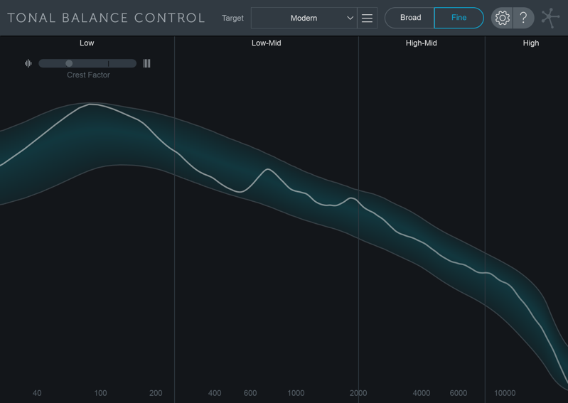
Displays the selected target curve range in blue across the frequency spectrum. The white spectrum curve in this view represents your current track.
Band Indicators

The frequency band labels will turn white when your current track is within the typical range for the selected target curve.
Crest Factor
The Crest Factor meter shows information about the low end dynamic range of your track. When the meter is weighted to the left, it indicates that your mix is ‘too dynamic’ in the low end. When weighted to the right, it indicates that your mix is ‘too compressed’ in the low end.
Target Curves
Tonal Balance Control comes with 3 factory target curves that represent the typical spectral curves found in major musical styles.
- Orchestral
- Bass Heavy
- Modern
Custom Target Curves
Clicking on the menu button to the left of the target curve dropdown menu exposes options for creating your own target curves to use in Tonal Balance Control.
| Supported File Formats |
|---|
| AIFF |
| WAV |
| MP3 |
| M4A |
| FLAC |
| OGG |
Create custom target curve from file…
Opens a system window that allows you to select an audio file to create a custom target curve.
Create custom target from folder of files…
Allows you to select a folder of audio files. Tonal Balance Control will create a single target curve based on all audio files included in the selected folder.
Save custom target curve…
Save the custom target curve you created to use again in the future.
Change target curve folder…
Allows you to select a different location to store and recall target curves.
Default Target Curve folder locations
- Mac: Users/username/Documents/iZotope/Tonal Balance Control/Target Curves
- Windows: C:\Users\username\Documents\iZotope\Tonal Balance Control\Target Curves
Show target curve folder in Finder/Explorer…
Opens a Finder (Mac) or Explorer (Windows) window to the current target curve directory.
Options
You can access the Options menu by clicking the gear button in the upper right hand corner of the Tonal Balance Control interface.

- Version String: The current Tonal Balance Control version and build number are listed in a string located in the upper right hand corner of the Options window.
- Reset: Resets all Tonal Balance Control options to their factory default values.
- Cancel: Exits the Options window without saving any changes made since last opening the Options window.
- Ok: Exits the Options window and saves any changes made since last opening the Options window.
General
- Enable Analytics: When enabled, anonymous usage data will be sent to help iZotope improve future products.
- Enable Tooltips: When checked, tooltips with information about a control will appear when hovering the cursor over most controls in the Tonal Balance Control interface.
Spectrum
- Average Time: Averages the spectrum according to this setting. Higher average times can be useful for viewing the overall tonal balance of a mix, while shorter average times provide a more real-time display.
- Frequency Scale: Sets the frequency scale used by the Tonal Balance Control meter. Choices include:
- FLAT LOG
- EXTENDED LOG
- PIANO ROLL
Note
You can access and change the frequency scale option without opening the options window by right-clicking on the frequency ruler in the Tonal Balance Control interface.
Ozone & Tonal Balance Control
Select Ozone 8 instances from the plug-in selection menu in Tonal Balance Control to modify EQ parameters remotely or view the spectrum metering of any Ozone 8 plug-in.
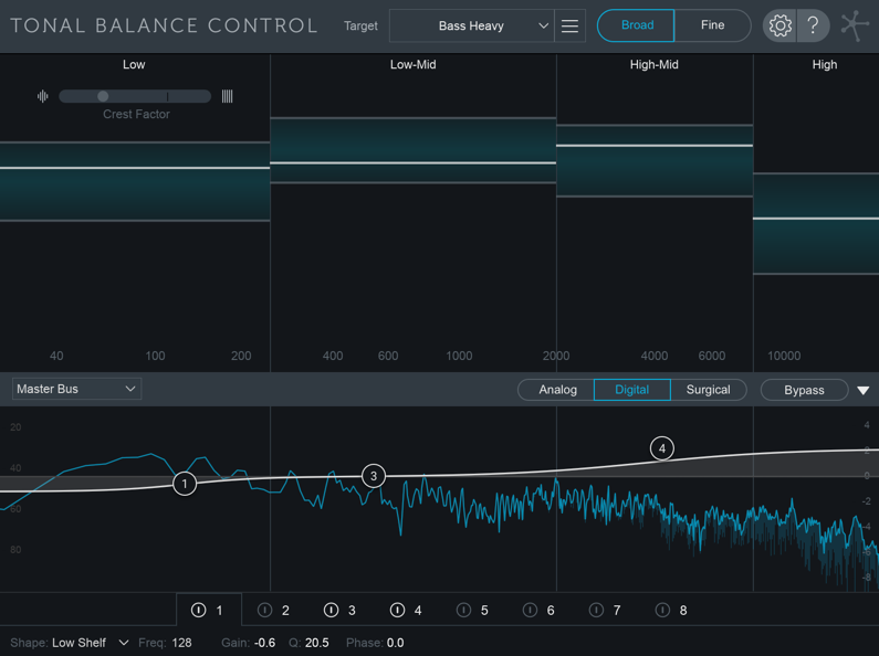
The following table outlines the controls and displays available when the associated Ozone 8 plug-in is selected as the incoming instance in Tonal Balance Control.
| Plug-in/Module Name | EQ Controls | Spectrum Display |
|---|---|---|
| Ozone 8 / EQ module | Yes | Yes |
| Ozone 8 / Post EQ module | Yes | Yes |
| Ozone 8 EQ | Yes | Yes |
| Ozone 8 Dynamic EQ | NO | Yes |
| Ozone 8 Dynamics | NO | Yes |
| Ozone 8 Exciter | NO | Yes |
| Ozone 8 Imager | NO | Yes |
| Ozone 8 Maximizer | NO | Yes |
| Ozone 8 Spectral Shaper | NO | Yes |
| Ozone 8 Vintage Limiter | NO | Yes |
| Ozone 8 Vintage EQ | NO | Yes |
| Ozone 8 Vintage Tape | NO | Yes |
| Ozone 8 Vintage Compressor | NO | Yes |
Ozone 8 plug-ins with no EQ controls will look something like this when selected in Tonal Balance Control:
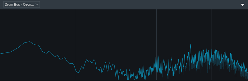
Ozone 8 plug-ins with compatible EQ controls will look something like this when selected in Tonal Balance Control:
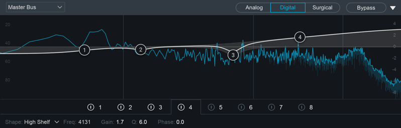
Global EQ Controls

Source Plug-in Selection Menu
Allows you to select the instance to display/control from within the Tonal Balance Control interface.
Global EQ Filter Mode
Sets the global EQ processing mode.
- ANALOG When selected, all EQ bands will use analog-modeled filters with minimum phase response.
- DIGITAL When selected, all EQ bands will use filter shapes with adjustable phase response
- SURGICAL When selected, all EQ bands will use precise digital filter shapes. Only select filter shapes are available in Surgical mode.
Bypass
Momentarily bypasses EQ processing in the selected Ozone 8 plug-in. This bypass control is useful for quick A/B comparisons.
Note about EQ Bypass state
- If the selected EQ is bypassed in the plug-in, the controls will appear dimmed in Tonal Balance Control. To enable the EQ in the selected plug-in, you will need to open the plug-in window and unbypass the EQ. EQ bypass state of a selected plug-in can’t be changed from the Tonal Balance Control interface.
Show/Hide Selected Plug-in Display
Toggles the incoming instance display panel open or closed.
Metering & Navigation
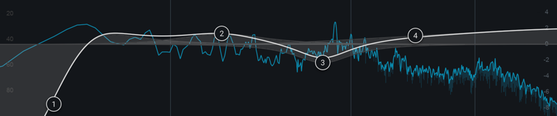
Spectrum Metering
Displays spectrum metering for the selected instance. Ozone 8 plug-ins will display their spectrum metering in blue.
EQ Curve
If the selected Ozone 8 instance supports EQ control, the EQ curve controls will be displayed in the spectrum meter area.
Tips for working with EQ nodes
- Change filter shapes: You can change filter shapes of any visible node by right-clicking on the node and selecting the filter shape from the context menu that appears.
- Reset node to default: Double-click on a node to reset it to default values.
- Enable bands with double-click: Double-click in an empty spot in the spectrum display to enable a band at that frequency/gain.
- BAND SELECTION & ENABLE/DISABLE CONTROLS

- EQ bands can be enabled or disabled by clicking on the power button to the left of the band number.
- Click on the band number directly to view the controls associated with that band.
EQ Controls
EQ controls for the currently selected Ozone EQ are located in the bottom bar of the Tonal Balance Control interface.

- BAND SHAPE: Selects the filter shape used by the selected band.
- FREQUENCY: Sets the center frequency for the selected filter.
- GAIN: Sets the positive/negative gain applied to the selected filter.
- Q: Sets the bandwidth of current filter.
- PHASE (Digital/Surgical Mode Only): Controls the mixed phase response of the current band. 0% = Linear phase response; 100% = minimum phase response.
General Notes
Control Availability
The following controls are accessible in the Ozone 8 EQ/Post EQ modules and EQ component plug-in, but cannot be accessed from the Tonal Balance Control interface:
- EQ module/plug-in Bypass
- Matching EQ controls
- Mid/Side or Left/Right processing mode controls
- EQ module reset
- I/O or Channel Ops controls
M/S & L/R control limitation in Tonal Balance Control
If the Ozone EQ instance selected in Tonal Balance Control is using Mid/Side or Left/Right processing modes, the EQ controls will not appear in the Tonal Balance Control interface. Currently, Tonal Balance Control only supports controlling Ozone EQs that are utilizing Stereo processing mode.
Options
Overview
Ozone allows you to adjust a comprehensive set of options. You can access the Options menu by clicking on the gear button in the upper right hand corner of the interface.

The bottom of the options window includes the following global parameters:

- ?: Launches this help documentation chapter.
- Reset: Resets all Options in the currently selected options tab to their factory default value.
- Version information: Displays the current Ozone version and build number.
- Cancel: Closes the Options window without saving changes.
- Ok: Closes the Options window and saves changes.
General

Graphics
- ENABLE METERS: Allows you to quickly turn on/off all meters.
- SHOW TOOLTIPS: Enables/disables informational note displays when hovering over controls.
- DIM CONTROLS WHEN BYPASSED: When this option is enabled, each module’s controls will be dimmed when the module is bypassed. This feature helps to remind you when a module is bypassed, so that you don’t make adjustments to a bypassed module unintentionally.
- MODULE PRESET MANAGER FOLLOWS MODULE SELECTION: When this option is enabled, the Module Preset manager will display the presets for the currently selected module. If disabled, the currently displayed Module Preset manager will not change when different modules are clicked on.
- FRAME RATE LIMITER: Allows you to set the speed (frames per second) that Ozone should use to display and update meters. In most cases the default will provide smooth displays while still allowing adequate processing time for audio.
- WINDOW OPACITY: Adjusts the transparency of the Ozone plug-in window, allowing you to see through the Ozone plug-in window while still having access to Ozone’s controls. This can be Note that this option isn’t available in the Ozone application.
Authorization & Updates
- CHECK FOR UPDATES: Sets how often Ozone will check for updates. You can choose between: Never, Daily, Weekly, and Monthly.
- CHECK NOW: Allows you to manually check if updates are available.
- AUTHORIZE: Launches the authorization wizard. For additional information on authorizing Ozone, you can visit the Authorization chapter or click the More
Info button explained below.
- REMOVE AUTHORIZATION: If authorized, allows you to remove your current Ozone authorization.
- MORE INFO: Launches the iZotope support page about authorization.
Other
- ENABLE ANALYTICS: Check this box to allow Ozone to upload data on your usage patterns of the application to iZotope’s servers. This information is anonymous, and allows us to better understand how users interact with Ozone, in order to provide the best updates possible in the future.
- HISTORY DEPTH: Sets the number of undo history steps that will save to the history list.
- KEYBOARD SUPPORT: The keyboard support option must be set to “full” for all keyboard shortcuts to be available. You can choose between: Full, Minimal, and None.
Master Assistant
- LOUDNESS TARGET: Sets the loudness target value used for Maximizer Threshold learning when running Master Assistant with “Streaming” selected as the Target.
Plug-in Host
- HOST SYNC: Displays information about your host application’s transport state.
- VIEW BUFFERS: Allows you to capture information about the buffer sizes Ozone is receiving from your host application.
- DELAY COMPENSATION: Displays information about the amount latency introduced by Ozone processing.
Spectrum Options
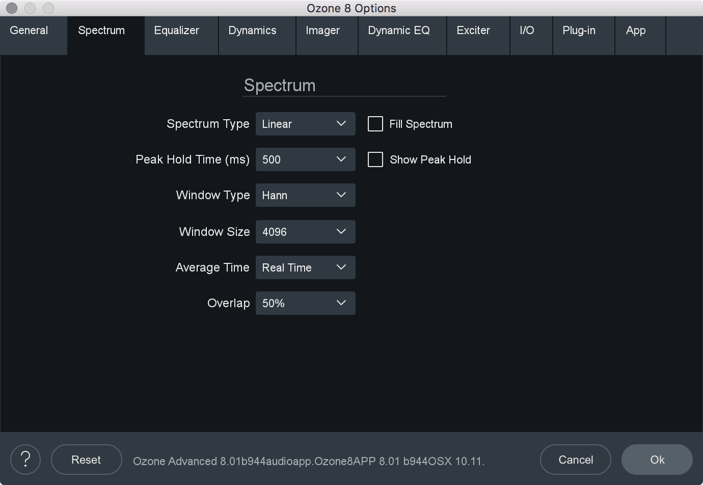
- SPECTRUM TYPE: Allows you to modify the spectrum analyzer display type. You can choose between:
- LINEAR: A continuous line connecting the calculated points of the spectrum.
- 1⁄3 OCTAVE: Splits the spectrum into bars with a width of 1⁄3 of an octave. Although the spectrum is split into discrete bands, this option can provide excellent resolution at lower frequencies.
- CRITICAL: Splits the spectrum into bands that correspond to how we hear, or more specifically how we differentiate between sounds of different frequencies. Each band represents sounds that are considered “similar” in frequency.
- FULL OCTAVE: Splits the spectrum into bars with a width of one full octave.
- FILL SPECTRUM: Allows you to display the real-time spectrum as a solid graph as opposed to a line graph. This option can be used to differentiate the real-time spectrum from the peak hold spectrum.
- WINDOW SIZE: Controls the tradeoff between time and frequency resolution in the spectrum analyzer. Higher values offer greater frequency resolution.
- WINDOW: Selects a window type for the spectrum. In most cases the default window type will work well, but you can choose from a variety of window types. Each window type has different amplitude and frequency resolution characteristics.
- PEAK HOLD TIME: Sets the length of time the peak hold display will hold before updating. You can choose between specific hold times (in milliseconds) or Infinite, where the peak display is held indefinitely.
Reset Peak hold
- You can reset the Peak Hold display manually by clicking on the spectrum.
- SHOW PEAK HOLD: Toggles whether Ozone displays and holds the peaks of the spectrum.
- AVERAGE TIME: Averages the spectrum according to this setting. Higher average times can be useful for viewing the overall tonal balance of a mix, while shorter average times provide a more real-time display.
- OVERLAP: Controls how often the spectrum updates. More overlap will cause the spectrum to update more frequently, at the expense of increased CPU usage.
EQ
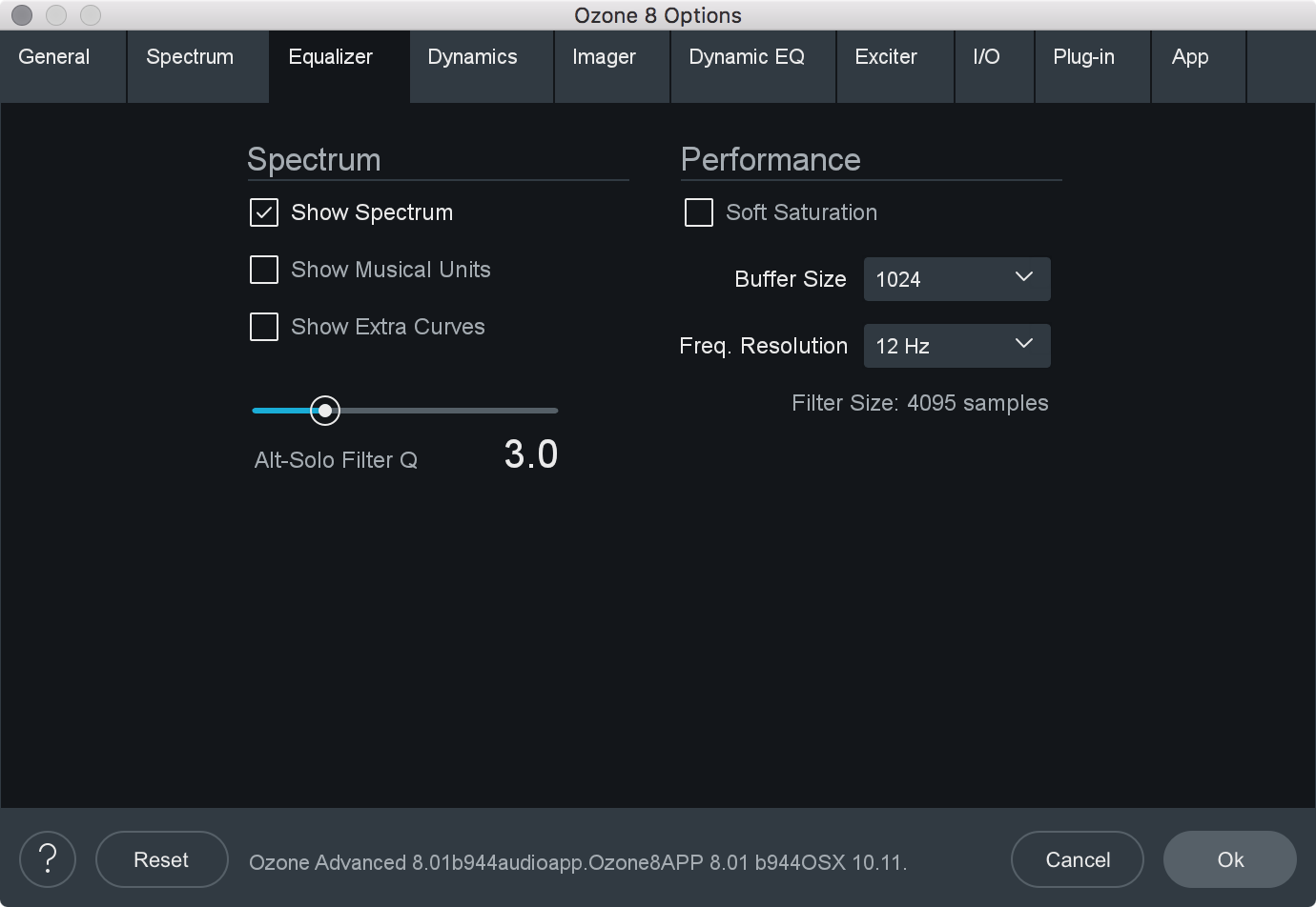
- SHOW SPECTRUM: When enabled, displays a real-time spectrum analyzer in the Equalizer spectrum area. This can be very useful in showing the frequency balance of your mix and how it is changed as you apply equalization.
- SHOW MUSICAL UNITS: When enabled, displays musical note labels along the frequency axis of the spectrum analyzer, alongside the Hertz ruler.
- SHOW EXTRA CURVES: Toggles the display of Phase Delay, Phase Response, and Group Delay curves in the EQ spectrum.
- SOFT SATURATION: Enables Soft Saturation in the EQ module. When enabled, signals that clip as a result of being boosted by the EQ will saturate with an analog character, rather than harsh digital clipping.
- BUFFER SIZE: Adjusts the memory buffer size, measured in samples, Ozone uses when applying equalization to the signal.
- FREQUENCY RESOLUTION: Selects the minimum resolution, in Hz, the Equalizer can be adjusted by. You can choose between: 3 Hz, 6 Hz, 12 Hz, 24 Hz, and 48 Hz.
- FILTER SIZE: Adjusts the steepness of the filter setting used in the EQ module.
- ALT-SOLO FILTER Q: Sets the bandwidth (Q) of the Alt-Solo Feature.
Exciter
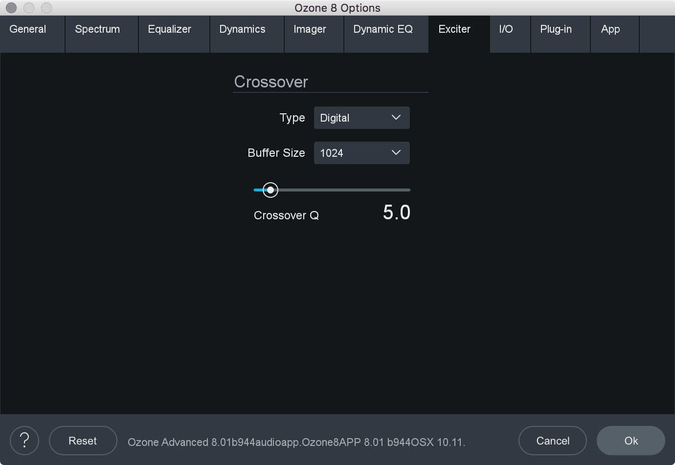
- CROSSOVER TYPE: Sets the crossover type used for multiband processing in the Exciter.
- ANALOG: Provides a natural analog character.
- DIGITAL: Provides a more transparent sounding crossover.
- HYBRID: A perfect reconstruction IIR analog crossover designed to reduce phase distortion and frequency distortion found in other analog crossovers while maintaining precise crossover points and the warm characteristics of analog crossovers.
- CROSSOVER BUFFER SIZE: Determines how large of a digital audio buffer is used in the Exciter module crossovers.
- CROSSOVER Q: When using the Digital crossover type, you can manually set the bandwidth of the crossover points in the Imager module crossovers. A higher Q results in tighter crossovers, while a lower Q provides a more gradual transition from one band to the next.
Dynamics Options
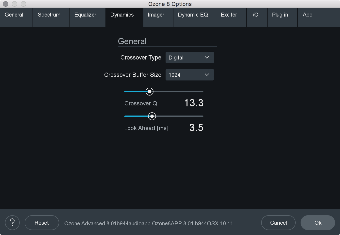
- LOOK AHEAD TIME: Determines how far ahead the dynamics processor looks ahead, within the loaded digital audio file, in order to provide as transparent and effective dynamics controls as possible. The look ahead time ranges from 0 to 10 ms.
- CROSSOVER TYPE: Sets the crossover type used for multiband processing in the Dynamics module.
- ANALOG: Provides a natural analog character.
- DIGITAL: Provides a more transparent sounding crossover.
- HYBRID: A perfect reconstruction IIR analog crossover designed to reduce phase distortion and frequency distortion found in other analog crossovers while maintaining precise crossover points and the warm characteristics of analog crossovers.
- CROSSOVER BUFFER SIZE: Determines how large of a digital audio buffer is used in the Dynamics module crossovers.
- CROSSOVER Q: When using the Digital crossover type, you can manually set the bandwidth of the crossover points in the Imager module crossovers. A higher Q results in tighter crossovers, while a lower Q provides a more gradual transition from one band to the next.
Dynamic EQ Options

- SHOW MUSICAL UNITS: When checked, the Dynamic EQ will show its frequency points as musical notes (for example, A4) instead of measured in Hz.
- SHOW SPECTRUM: When enabled, displays a real-time spectrum analyzer in the Dynamic EQ spectrum area. This can be very useful in showing the frequency balance of your mix and how it is changed as you modify processing.
- ALT-SOLO FILTER Q: Controls the bandwidth (Q) of the filter used in the Dynamic EQ. The setting ranges from .2 to 12.
Imager Options
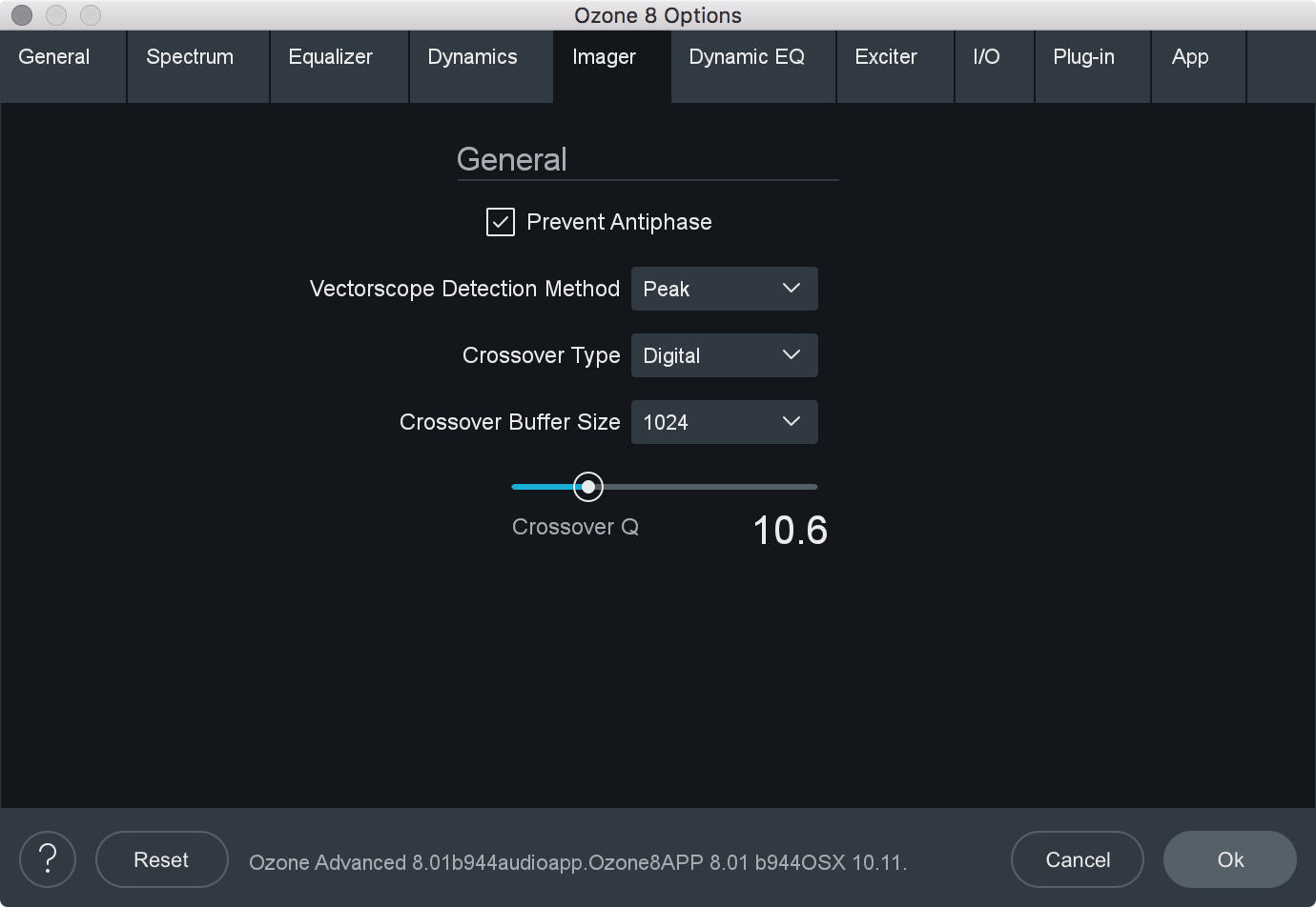
- PREVENT ANTIPHASE: When checked, the Imager will automatically prevent any settings from being applied that would result in phase cancellation of the stereo signal, when summed to mono.
- VECTORSCOPE DETECTION METHOD: Chooses which type of amplitude detection method is used by the Vectorscope. Choices include:
- PEAK: When this option is enabled, Ozone’s detection circuit looks at peak levels of the incoming signal. In general this is useful when you’re trying to even out sudden peaks in your music.
- RMS: When this option is enabled, Ozone looks at the average level of the incoming signal. RMS detection is useful when you’re trying to increase the overall volume level without changing the character of the sound.
- ENVELOPE: Envelope mode behaves much like RMS mode, but with some key advantages. Unlike RMS, True Envelope mode produces even levels across all frequencies.
- CROSSOVER TYPE: Sets the crossover type used for multiband processing in the Imager module.
- ANALOG: Provides a natural analog character.
- DIGITAL: Provides a more transparent sounding crossover.
- HYBRID: A perfect reconstruction IIR analog crossover designed to reduce phase distortion and frequency distortion found in other analog crossovers while maintaining precise crossover points and the warm characteristics of analog crossovers.
- CROSSOVER BUFFER SIZE: Determines how large of a digital audio buffer is used in the Imager module crossovers.
- CROSSOVER Q: When using the Digital crossover type, you can manually set the bandwidth of the crossover points in the Imager module crossovers. A higher Q results in tighter crossovers, while a lower Q provides a more gradual transition from one band to the next.
I/O
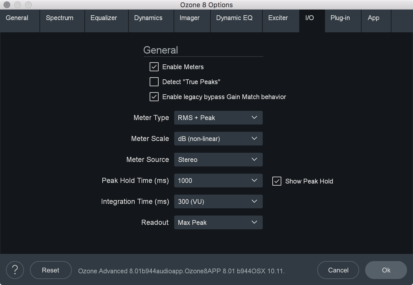
- ENABLE METERS: Enables or disables the meters in Ozone’s master I/O section.
- SHOW PEAK HOLD: Displays peak hold bars in the I/O meters.
- DETECT TRUE PEAKS: By default the Input/Output meters will only indicate clipping which occurs within the digital domain. To accurately measure the signal that will result from digital to analog conversion, select Detect “True Peaks.”
- ENABLE LEGACY BYPASS GAIN MATCH BEHAVIOR: Determines the behavior of the Gain Match feature in the auditioning section.
- BEHAVIOR WHEN CHECKED: When Ozone is on there are many modules such as the multiband dynamics and loudness maximizer that can affect the overall or perceived loudness of the mix. This makes it very hard to compare “Ozone on” to “Ozone bypassed.” The “Automatically Match Effective Gain When Bypassed” feature solves this problem. Ozone determines how much perceived gain is being added by all of the active Ozone modules and then automatically adds this amount of gain when Ozone is put into bypass mode. You can bypass Ozone, and the gain is automatically adjusted so that when you A/B Ozone on and off, the apparent volume is the same. This gain processing is the only processing that is applied when Ozone is bypassed, and it is of course only applied when Ozone is actually bypassed.
Note
- In the plug-in version of Ozone, this may not work if you use the host application to bypass Ozone. If the host application reports that it is bypassed, it will work and the Bypass button in Ozone will automatically depress accordingly. If the host does not report that it is bypassed, Ozone doesn’t know and therefore cannot apply the “gain when bypassed.”
- In the plug-in version of Ozone, this may not work if you use the host application to bypass Ozone. If the host application reports that it is bypassed, it will work and the Bypass button in Ozone will automatically depress accordingly. If the host does not report that it is bypassed, Ozone doesn’t know and therefore cannot apply the “gain when bypassed.”
- BEHAVIOR WHEN UNCHECKED: Enabling Gain Match in the I/O section when this option is disabled will result in the output gain sliders auto-adjusting apparent output level to match the dry signal level. The output faders will turn blue when they are auto adjusting level. This is useful to A/B the effect of Ozone processing. Unlike the legacy auto gain behavior, we recommend turning Gain Match on and off as needed rather than keeping it enabled all the time. This behavior does affect the output of Ozone.
- BEHAVIOR WHEN CHECKED: When Ozone is on there are many modules such as the multiband dynamics and loudness maximizer that can affect the overall or perceived loudness of the mix. This makes it very hard to compare “Ozone on” to “Ozone bypassed.” The “Automatically Match Effective Gain When Bypassed” feature solves this problem. Ozone determines how much perceived gain is being added by all of the active Ozone modules and then automatically adds this amount of gain when Ozone is put into bypass mode. You can bypass Ozone, and the gain is automatically adjusted so that when you A/B Ozone on and off, the apparent volume is the same. This gain processing is the only processing that is applied when Ozone is bypassed, and it is of course only applied when Ozone is actually bypassed.
- METER TYPE: Ozone 8 allows the I/O meters to display peaks according to several different audio monitoring types, including:
- RMS: RMS (Root Mean Square) is a software-based implementation of an analog-style level meter. Using different integration times, you can model popular VU or PPM meters. The RMS meter displays the average level calculated over a short window of time. The RMS meter readout will typically be lower than an equivalent PPM meter (Digital/Analog), since it is averaging peaks into the overall loudness.
- PEAK: The Peak meter is a fast meter that measures instantaneous maximum sample value or peak analog waveform values, depending on the “detect inter-sample peaks” checkbox. If you are tracking the peaks for possible clipping, the Peak meter is appropriate.
- RMS + PEAK: This is a combined RMS and Peak meter. This meter displays a lower bright bar representing the average level (RMS) and a higher dimmer bar representing peak level. There is also a moving line above the bar representing the most recent peak level or peak hold.
- K-SYSTEM: Ozone 8 supports Bob Katz’s K-System metering with simultaneous peak and RMS displays.
- MOMENTARY: This measurement is a calculation of loudness over the course of 400ms.
- SHORT TERM: This measurement is a calculation of loudness over the course of 3 seconds.
- INTEGRATED: This measurement is a calculation of loudness over the course of an indefinite period of time.
- SCALE: This sets the range and scale of the I/O Meters. Options include:
- dB (Linear): Decibel scale presented linearly from -60 dB to 0
- dB (Non-linear): Full decibel scale (dBfs) presented non-linearly
- BS.1771: Loudness scale recommended by the ITU that spans from -45 LUFS to -14.0 LUFS
- EBU +9: Loudness scale recommended as a default by the EBU that spans from -41.0 LUFS to -14.0 LUFS
- EBU +18: Loudness scale recommended for material with a wide Loudness Range by the EBU that spans from -59.0 LUFS to -5.0 LUFS.
LUFS Note
- LUFS is Loudness Units Full Scale and 1 LUFS = 1 dB.
- SOURCE: Selects the audio source for the input/output meters. You can choose between: Stereo & Mid/Side. Ozone’s I/O meters display Stereo information by default. To change the Input/Output meters to display Mid/Side metering information, click on the I/O button above the I/O meters and change “Source” selection to Mid/Side. When the I/O meters are in Mid/Side mode, the meter in the center represents the Mid channel level information and the meters on the left and right represents Side channel level information. The left and right gain sliders control the left and right gain of your signal, regardless of the Meter Source selection.
- PEAK HOLD TIME: Selects how many consecutive samples of audio must exceed 0 dBFS (full scale) before registering as a peak. You can choose between: 5 ms, 250 ms, 500 ms, 1,000 ms, 5,000 ms, and Infinite.
- INTEGRATION TIME: Specifies the integration time for the RMS calculation. In most RMS meters, the integration time is set to around 300 ms. You can chhose between: 10 ms, 50 ms, 300 ms (VU), 1,475 ms, 2,650 ms, 3,825 ms, and 5,000 ms.
- READOUT: Selects whether the peak hold section of the meters displays the current peak status (current) or instead displays the highest peak that has occurred in the audio file (max peak).
Ozone App Specific
The Ozone application options menu includes tabs that are specific to the application. These tabs allow you to manage plug-in scanning and application specific behaviors.
Plug-in
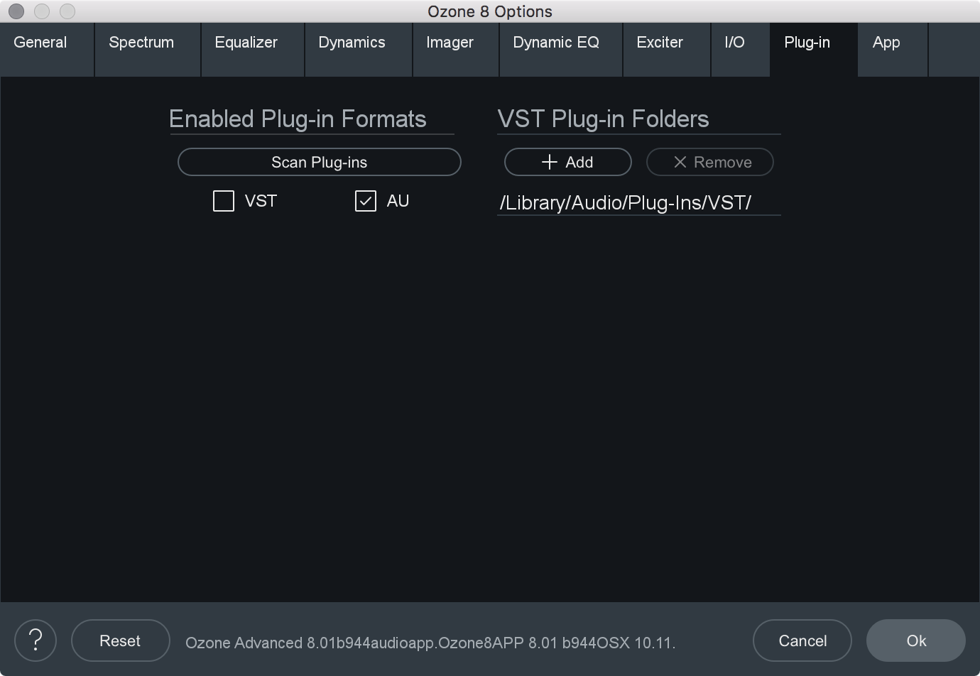
- ENABLED PLUG-IN FORMATS: Allows you to individually select which plug-in formats (VST and AudioUnit) will be automatically loaded into Ozone’s “Plug-ins” section.
- SCAN PLUG-INS: Click this button to re-scan the selected plug-in locations and load in any newly installed plug-ins.
- VST PLUG-IN FOLDERS:
- Displays the currently monitored folder path of where your VST plug-ins reside that are loaded into the “Plug-ins” section of Ozone.
- Use in conjunction with the “Add VST Folder” to add a new location, or the “Delete VST Folder” to delete a currently displayed folder path.
Note about AudioUnit Plug-ins
- AudioUnit plug-ins (OS X/macOS only) do not require you to specify a folder path. AudioUnit plug-ins are always installed to a standard folder location on OS X, and Ozone will look to that specific folder path to scan any installed AudioUnit plug-ins.
App
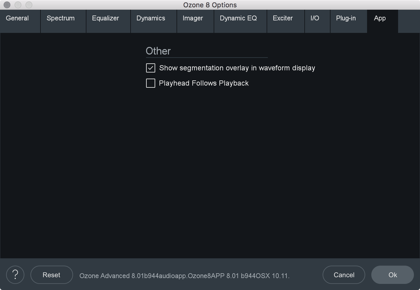
- ENABLE WAVEFORM SEGMENTS OVERLAY: Click to enable the Waveform Segmentation overlay, which is the multicolored bar located just below the waveform. In Ozone 8, every imported audio file is scanned for matching “segments,” which are displayed as colored bars. This display acts as a helpful color coding of the sections of a song. A mastering engineer can use this display to quickly check every transition, or alternatively A/B the chorus of one song with the chorus of another. The corresponding audio can be selected by clicking on the colored segment, this allows you to easily select a loop region or quickly jump to different sections of a file.
- PLAYHEAD FOLLOWS PLAYBACK: When this control is checked, the playhead will always stop at the location that the stop button is pressed, as opposed to returning to the start position.
Plug-in Automation
Overview
Automation allows you to specify changes to parameters over the duration of a mix, such as stereo widening during a chorus or boosting an EQ during a solo. You can automate hundreds of parameters in Ozone, using any host application that supports e ects automation.
Using Automation in Ozone
The implementation and specifics of automation are dependent on the host application; please refer to the documentation of your host app for setting up an automated mix.
In general, you insert Ozone as an ordinary effect on a track, and then in the track view of the host app assign automation envelopes to it.
The automation envelopes control how Ozone parameters are changed over the course of the mix. In this case, most of your tweaking is done in the track view of the host app, dragging curves and envelopes as opposed to changing controls in Ozone.
Ozone Automation Parameter Names
We have done our best to provide the controls with intelligent names, but it can be overwhelming when you initially see the very large list of automatable parameters in Ozone.
When scrolling through the list, remember that each multiband module has up to 4 bands per parameter.
For example, “Dynamics: Comp Thresh Band 1” corresponds to the Compressor Threshold setting in Band 1 of the Dynamics module.
When automating parameters in the EQ module, it is important to note that Stereo/Mid/Left parameters are labeled with the “St/M/L” prefix, and Side/Right parameters are labeled with the “S/R” prefix.
When automating a control from the track view, you can see the control on the Ozone interface move, under the control of the host application. We purposely do not update the position of the control as often as we could, as it takes CPU power to redraw controls, power that is ideally reserved for processing audio. So we update the drawing of the control less frequently. It may look like the control is moving in steps, but rest assured that the audio is being processed smoothly.
Opacity Control
When automating in a track view with envelopes, but working mainly with the Ozone interface, we found it helpful to be able to “see through” Ozone so you can monitor Ozone meters and controls, but see the track view and automation curves behind Ozone. Thus, we have provided an Opacity slider in the main options dialog (plug-in version only, available at Settings -> General -> Graphics -> Opacity).
This allows you to see through Ozone to monitor both what Ozone is doing and what is happening with the automation curves.
Note that this is not available in all host applications, and it does require more CPU power than a standard “opaque” plug-in if you set the Opacity to less than 100%.
Tips & Examples
Tips for optimizing Ozone’s performance
Unlike many single task plug-ins, Ozone 8 harnesses the power of six plug-ins in one, and performs a significant number of calculations when running. The combination of multiple DSP modules performing analog modeling and a half dozen real-time meters dictates that it requires more CPU processing than a typical plug-in.
While continuing to push the limits of high-quality audio signal processing, Ozone 8 offers significant improvements concerning CPU optimization, allowing your sessions to run more efficiently.
If you do start to reach the limits of your particular machine, here are some tips for optimizing your CPU:
- Remove any modules that are not in use from the signal chain.
- If using Ozone’s Digital EQ, adjust your EQ buffer sizes for optimal performance. See Buffer Sizes for details.
- If using the Digital crossover type in any multiband module, try adjusting the Crossover Buffer Size in the options menu.
- If using the Ozone plug-ins within a host application, try changing the buffer size and/or latency setting in the host application.
- When buffers are too high (latencies are too large), meters will update very slowly and performance may suffer.
- As buffers become very small (latencies are very low), the EQ and crossover will consume more CPU power.
- You can disable meters in their option screens.
- Using fewer crossover bands can save significant CPU power. Try using one- or two-band dynamics, for example, instead of all four bands. See the Multiband Modules section of the Common Module Controls chpater for instructions on how to change the number of crossover bands.
- If you are using Ozone 8 Advanced and are using less than four modules, try using the modules as individual component plug-ins to reduce CPU power.
Buffer Sizes
Ozone 8 contains advanced controls to help you get the optimal performance for your setup. Since Ozone contains several modules within its internal DSP chain, there are several places where you can control its internal buffer sizes.
In general, the default values should give good performance on most systems; however, there are some aspects of host applications that are not detectable by plug-ins. Read this section for instructions on how to optimize Ozone for your particular setup.
Setting Buffer Sizes for Independent Modules
Ozone’s Equalizer requires fixed buffers when set to certain modes. You can set its buffer size independently using its options tab. These buffer sizes default to reasonable values, and most users should be able to use Ozone right away without tweaking them.
Evaluating Host Buffer Sizes in Ozone
You can use Ozone’s Buffer Size Viewer to evaluate what kinds of buffers the host application is sending to Ozone (only applicable in the Ozone plug-ins).
- Open the View Buffers window in Ozone by navigating to:
- Options -> General -> Host -> View Buffers. Once you know what size buffers your host application is sending, try the following:
- Add the EQ module to the signal chain and remove all other modules from the chain.
- Ensure the EQ module is set to ‘Digital’ mode.
- Set the EQ filter size to the size you most commonly use.
- Set the EQ buffer size to the number that’s closest to your host application buffer size (displayed in the View buffers window)
- Open a CPU meter.
- Many host applications have a CPU meter built in, but if you’re running Windows you can also press Ctrl+Shift+ESC and select the Performance tab. Note that CPU meters are usually somewhat inaccurate, but we’re just looking for relative changes in CPU usage.
- Add an audio file to the track with Ozone on it (or send the output of a track to the bus that Ozone is inserted on).
- Ensure the file you are using is similar to files you typically work with (ie. sampling rate, bit depth, number of channels).
- If you usually use Ozone in a multitrack environment then be sure to do the same here.
- Play back audio.
- As the audio plays, try adjusting the EQ buffer size while monitoring the CPU meter, to see if certain buffer sizes have a positive effet on CPU consumption.
- Buffer sizes near the host application buffer size are a good starting point, but the best choice depends on many aspects of your system and host application, which are beyond Ozone’s control.
- Following the steps above ensures that Ozone’s CPU consumption is optimized for your current session parameters.
- If you change your session configuration, for example, if you move from 44.1 kHz to 96 kHz, or you change from a single-track setup to a multi-track setup, then you may want to repeat these steps to make sure your buffer settings are still optimal.
We’ve gone to great lengths to optimize Ozone’s internal DSP without compromising sound quality. We hope these steps help make Ozone useful in a wide variety of setups. These steps should help you address those variables which are beyond our control and quite often very different for different users.
Using Mastering Presets in Ozone 8
Ozone’s presets are designed to give you a quick starting point for mastering your own projects.
Every mix is different, so no preset can perfectly master your project. However, we have attempted to provide a wide range of presets that will help you nd a good starting point for mastering your own material. By starting with a preset, you’ll be able to tweak these presets to make them more closely fit the session you’re working on.
We recommend you download the Ozone Mastering Guide, to learn the basic principles of mastering with Ozone. Presets can take you a long way, but learning how each of Ozone’s mastering modules works is key to getting the best results. You won’t regret it; your masters will sound better than ever before!
Setting Your Input Level
Setting the input level in Ozone can make a huge difference in how the Dynamics modules in Ozone behave. Setting your input level is also important when selecting presets, as the presets will sound drastically di erent if your input level is too loud or quiet.
As a starting point, try setting Ozone’s input level so that the input meter is peaking upper half to upper quarter of the meter. It is OK if the input meter peaks close to the top when Ozone’s Maximizer module is enabled, since it will keep the audio from clipping.
Choosing a Starting Point
Start by listening through several of Ozone’s presets. The presets contain helpful descriptions based on the outcome they will produce on your audio. Alternatively, you can start with a genre-based mastering preset, or simply use the general-purpose mastering presets.
Because every mix is different, we’ve aimed to give you a lot of starting points so that you can choose the best one for your project. When you’ve found one that sounds like it has what your mix needs, you can start tweaking that preset to your liking.
Dithering Tips
When Using the Plug-In Version of Ozone 8:
- Do not perform any processing to the audio after it has been dithered with Ozone. You may perform level adjustment with the output gain sliders in Ozone (those come before the dither) but do not change any levels in the host app or with other plug-ins.
- Almost all host apps have their master faders after the effects slot, so any level adjustment in the host app will destroy the dither.
- Do not put any plug-ins after Ozone if you are dithering with Ozone. The dither must be the last thing that touches the audio.
- Turn off dithering in the host app. Basically, you just want to truncate (throw away) the bits, because they’re just zero anyhow.
Relative Parameter Linking in Ozone
Parameter linking in Ozone allows for relative linking of parameter values. This means that parameter values will be linked relative to their values at the time they are linked.
Relative Linking Example
- Enable M/S mode in the Exciter.
- Adjust Mid Channel: Band 1 Mix to 50%
- Enable Mid/Side Link
- Adjust Side Channel: Band 1 Mix to 75%
- Return to Mid Channel view and notice that Mid Channel: Band 1 Mix is now set to 25%
Mid/Side Processing Examples
Using Mid Processing in the EQ Module
- Select Mid/Side mode in the EQ module and click “Mid” to reveal the Mid EQ curve. Then click the small “s” to solo the Mid channel.
- When you play an audio file in this mode, you will only hear the content assigned to the center of your soundstage, which is typically your lead vocal, other lead instruments, etc.
- Now select an EQ node around 1 kHz and boost the EQ node about 6 dB. This frequency specific boost at 1 kHz will only be applied to the center of your soundstage and can bring up the lead vocal in the mix without affecting the other instruments or the stereo separation of the entire frequency range.
Using Side Processing in the EQ Module
- Select Mid/Side mode in the EQ module and click “Side” to reveal the Side EQ curve. Click the small “s” to solo the Side channel.
- When you play an audio file in this mode, you will only hear the content at the edges of your soundstage which is typically reverb tails or instruments that are panned to an extreme side.
- Now select an EQ node around 6 kHz and boost the blue EQ curve about 6 dB. This frequency specific boost at 6 kHz will only be applied to the edges of your soundstage. The effect when applied will result in greater stereo widening and a richer, fuller sound.
Using Mid/Side Processing in the Exciter Module
Using the Side channel in the Harmonic Exciter module, try selecting the upper frequency bands for your mix. By increasing the amount sliders for the upper frequencies you will be applying the exciter to the extreme edges of your mix only and leaving the Mid (center) channel as-is.
Using Mid/Side Processing in the Dynamics Module
When dealing with multiband compression on a stereo mix, it is sometimes diffcult to apply processing to a specific instrument or vocal if they are too close in frequency.
In these cases, Mid/Side processing reveals more re ned control by allowing you to separate a specific frequency range into its Mid and Side components and apply compression separately to the Mid (center) channel, or the Sides of your mix.
There are many uses for Mid/Side processing using compression. For example, this can help prevent other instruments from being affected by compression on the lead vocal, since the vocal is usually in the center of your mix and other instruments are typically found at the sides of your mix.
Authorization
Overview
The first time you open the Ozone 8 application or Ozone 8 plug-in(s), the Authorization window will appear.
The Authorization window allows you to:
- TRIAL: Start or continue a Trial period evaluation prior to purchasing
- DEMO: Continue evaluating the product with Demo limitations (after the 10 day Trial period has been exceeded)
- AUTHORIZE: Authorize the product with a serial number
Trial & Demo Modes
A 10 day trial period will start when you first open the Ozone 8 application or Ozone 8 plug-ins. After the 10 day trial period has expired, Ozone 8 will enter demo mode. To disable Trial or Demo mode, you must authorize the product with a valid serial number.
Trial mode
Trial mode begins when the Ozone 8 application is first opened or when an Ozone 8 plug-in is first instantiated in a DAW/NLE. The authorization wizard window will display the number of days remaining in your trial period.
Clicking on the “Continue” button will dismiss the Authorization window and allow you to continue evaluating Ozone 8 in trial mode.
Demo mode
After 10 days, Ozone 8 will operate in Demo mode. In Demo mode, saving and exporting are disabled in the Ozone 8 application and is limited to 30 seconds of continuous playback. Ozone 8 plug-ins will periodically output silence when operating in demo mode. If you would like to continue evaluating Ozone 8 in demo mode, click the “Demo” button.
Authorizing Ozone 8
We offer three main methods for authorizing Ozone 8:
- Online Authorization: Use this method to authorize Ozone 8 on a machine that is connected to the internet.
- Offline Authorization: Use this method to authorize Ozone 8 on a machine that is not connected to the internet.
- iLok Authorization: Use this method to authorize Ozone 8 using an iLok.
More Information
For information on authorization, please visit the iZotope at:
https://www.izotope.com/authorization
Contacting iZotope Customer Care
For additional help with authorizing Ozone 8 application:
- Check out the Customer Care pages on our website: http://www.izotope.com/support
- Contact our Customer Care department at support@izotope.com
For more information on iZotope’s Customer Care department and policies can be found in the iZotope Customer Care section.
iZotope Customer Care
How to purchase the full version of Ozone 8
If you are using the demo version of Ozone 8 and would like the full version, you can purchase Ozone 8 direct from the iZotope online store: www.izotope.com/store
Once your purchase is complete, you will be sent an email confirmation and a full version serial number that can be used to fully authorize your current installation of Ozone 8.
iZotope Customer Care policy
iZotope is happy to provide professional technical Customer Care to all registered users absolutely free of charge. www.izotope.com/support/contact/index.php
We also offer valuable pre-sales technical Customer Care to customers who may be interested in purchasing an iZotope product. Before contacting iZotope Customer Care, you can search our Product Knowledgebase to see if the solution to your problem has already been published.
How long does iZotope provide customer support for purchased products? You can email us with any question for 12 months after you buy any iZotope product. Past 12 months, we’ll still help you with your account and authorization but will not provide technical support for in-depth product questions. If you need more detailed help on how to use the product, please check out our FAQs and Tutorials.
How long does iZotope support its products? Although we can’t guarantee it, we do our best to keep our products up to date with the operating systems and plug-in hosts that we support. Sometimes, other companies make changes that we’re not able to support, but we actively work with other companies to avoid these sorts of compatibility problems. We also do our best to address bug fixes within the product itself to ensure our products operate in accordance with our specifications.
We will provide software updates for 12 months from product release. After 12 months, no software updates will be provided.
For details on what operating systems and plug-in host software are officially supported for a product, please check that product’s Specs page.
Contacting iZotope Customer Care
For additional help with Ozone 8:
- Check out the Customer Care pages on our web site at www.izotope.com/support
- Contact our Customer Care department at support@izotope.com
iZotope’s highly trained Customer Care team is committed to responding to all requests within one (1) business day and frequently respond faster. Please try to explain your problem with as much detail and clarity as possible. This will ensure our ability to solve your problem accurately, the first time around. Please include all system specs and the build/version of Ozone 8 that you are using.
Once your Customer Care request is submitted, you will receive a confirmation email from iZotope Customer Care. If you do not receive this email within a few minutes, please check your spam folder and make sure our responses are not getting blocked. To prevent this from happening please add support@izotope.com to your list of allowed email addresses. International distribution
Customer Care is also available from our international distributors worldwide for any customers who purchased their iZotope products through a certified iZotope distributor.
Check with your local distributor for availability. If you would like help locating your local distributor please contact iZotope Customer Care.
Thanks for using Ozone 8!
-The iZotope Team
License Information
Anti-Grain Geometry
Version 2.4
Copyright © 2002-2005 Maxim Shemanarev (McSeem).
Redistribution and use in source and binary forms, with or without modification, are permitted provided that the following conditions are met:
Redistributions of source code must retain the above copyright notice, this list of conditions and the following disclaimer.
Redistributions in binary form must reproduce the above copyright notice, this list of conditions and the following disclaimer in the documentation and/or other materials provided with the distribution.
The name of the author may not be used to endorse or promote products derived from this software without specific prior written permission.
THIS SOFTWARE IS PROVIDED BY THE AUTHOR ``AS IS” AND ANY EXPRESS OR IMPLIED WARRANTIES, INCLUDING, BUT NOT LIMITED TO, THE IMPLIED WARRANTIES OF MERCHANTABILITY AND FITNESS FOR A PARTICULAR PURPOSE ARE DISCLAIMED. IN NO EVENT SHALL THE AUTHOR BE LIABLE FOR ANY DIRECT, INDIRECT, INCIDENTAL, SPECIAL, EXEMPLARY, OR CONSEQUENTIAL DAMAGES (INCLUDING, BUT NOT LIMITED TO, PROCUREMENT OF SUBSTITUTE GOODS OR SERVICES; LOSS OF USE, DATA, OR PROFITS; OR BUSINESS INTERRUPTION) HOWEVER CAUSED AND ON ANY THEORY OF LIABILITY, WHETHER IN CONTRACT, STRICT LIABILITY, OR TORT (INCLUDING NEGLIGENCE OR OTHERWISE) ARISING IN ANY WAY OUT OF THE USE OF THIS SOFTWARE, EVEN IF ADVISED OF THE POSSIBILITY OF SUCH DAMAGE.
Better Enums
Version 0.11.1
Copyright © 2012-2016, Anton Bachin. All rights reserved.
Redistribution and use in source and binary forms, with or without modification, are permitted provided that the following conditions are met:
Redistributions of source code must retain the above copyright notice, this list of conditions and the following disclaimer.
Redistributions in binary form must reproduce the above copyright notice, this list of conditions and the following disclaimer in the documentation and/or other materials provided with the distribution.
THIS SOFTWARE IS PROVIDED BY THE COPYRIGHT HOLDERS AND CONTRIBUTORS “AS IS” AND ANY EXPRESS OR IMPLIED WARRANTIES, INCLUDING, BUT NOT LIMITED TO, THE IMPLIED WARRANTIES OF MERCHANTABILITY AND FITNESS FOR A PARTICULAR PURPOSE ARE DISCLAIMED. IN NO EVENT SHALL THE COPYRIGHT HOLDER OR CONTRIBUTORS BE LIABLE FOR ANY DIRECT, INDIRECT, INCIDENTAL, SPECIAL, EXEMPLARY, OR CONSEQUENTIAL DAMAGES (INCLUDING, BUT NOT LIMITED TO, PROCUREMENT OF SUBSTITUTE GOODS OR SERVICES; LOSS OF USE, DATA, OR PROFITS; OR BUSINESS INTERRUPTION) HOWEVER CAUSED AND ON ANY THEORY OF LIABILITY, WHETHER IN CONTRACT, STRICT LIABILITY, OR TORT (INCLUDING NEGLIGENCE OR OTHERWISE) ARISING IN ANY WAY OUT OF THE USE OF THIS SOFTWARE, EVEN IF ADVISED OF THE POSSIBILITY OF SUCH DAMAGE.
FLAC
libFLAC and libFLAC++
Version 1.3.2
Copyright © 2000-2009 Josh Coalson
Copyright © 2011-2016 Xiph.Org Foundation
Redistribution and use in source and binary forms, with or without modification, are permitted provided that the following conditions are met:
Redistributions of source code must retain the above copyright notice, this list of conditions and the following disclaimer.
Redistributions in binary form must reproduce the above copyright notice, this list of conditions and the following disclaimer in the documentation and/or other materials provided with the distribution .
Neither the name of the Xiph.org Foundation nor the names of its contributors may be used to endorse or promote products derived from this software without specific prior written permission.
THIS SOFTWARE IS PROVIDED BY THE COPYRIGHT HOLDERS AND CONTRIBUTORS “AS IS” AND ANY EXPRESS OR IMPLIED WARRANTIES, INCLUDING, BUT NOT LIMITED TO, THE IMPLIED WARRANTIES OF MERCHANTABILITY AND FITNESS FOR A PARTICULAR PURPOSE ARE DISCLAIMED. IN NO EVENT SHALL THE FOUNDATION OR CONTRIBUTORS BE LIABLE FOR ANY DIRECT, INDIRECT, INCIDENTAL, SPECIAL, EXEMPLARY, OR CONSEQUENTIAL DAMAGES (INCLUDING, BUT NOT LIMITED TO, PROCUREMENT OF SUBSTITUTE GOODS OR SERVICES; LOSS OF USE, DATA, OR PROFITS; OR BUSINESS INTERRUPTION) HOWEVER CAUSED AND ON ANY THEORY OF LIABILITY, WHETHER IN CONTRACT, STRICT LIABILITY, OR TORT (INCLUDING NEGLIGENCE OR OTHERWISE) ARISING IN ANY WAY OUT OF THE USE OF THIS SOFTWARE, EVEN IF ADVISED OF THE POSSIBILITY OF SUCH DAMAGE.
fmt
Version 4.0.0
Copyright © 2012 - 2016, Victor Zverovich
All rights reserved.
Redistribution and use in source and binary forms, with or without modification, are permitted provided that the following conditions are met:
Redistributions of source code must retain the above copyright notice, this list of conditions and the following disclaimer.
Redistributions in binary form must reproduce the above copyright notice, this list of conditions and the following disclaimer in the documentation and/or other materials provided with the distribution.
THIS SOFTWARE IS PROVIDED BY THE COPYRIGHT HOLDERS AND CONTRIBUTORS “AS IS” AND ANY EXPRESS OR IMPLIED WARRANTIES, INCLUDING, BUT NOT LIMITED TO, THE IMPLIED WARRANTIES OF MERCHANTABILITY AND FITNESS FOR A PARTICULAR PURPOSE ARE DISCLAIMED. IN NO EVENT SHALL THE COPYRIGHT OWNER OR CONTRIBUTORS BE LIABLE FOR ANY DIRECT, INDIRECT, INCIDENTAL, SPECIAL, EXEMPLARY, OR CONSEQUENTIAL DAMAGES (INCLUDING, BUT NOT LIMITED TO, PROCUREMENT OF SUBSTITUTE GOODS OR SERVICES; LOSS OF USE, DATA, OR PROFITS; OR BUSINESS INTERRUPTION) HOWEVER CAUSED AND ON ANY THEORY OF LIABILITY, WHETHER IN CONTRACT, STRICT LIABILITY, OR TORT (INCLUDING NEGLIGENCE OR OTHERWISE) ARISING IN ANY WAY OUT OF THE USE OF THIS SOFTWARE, EVEN IF ADVISED OF THE POSSIBILITY OF SUCH DAMAGE.
FreeType
FreeType is licensed under the FreeType Project LICENSE.
Portions of this software are copyright © 1996-2002, 2006 The FreeType Project (www.freetype.org). All rights reserved.
gsl
Copyright © 2015 Microsoft Corporation. All rights reserved.
This code is licensed under the MIT License (MIT).
Permission is hereby granted, free of charge, to any person obtaining a copy of this software and associated documentation files (the “Software”), to deal in the Software without restriction, including without limitation the rights to use, copy, modify, merge, publish, distribute, sublicense, and/or sell copies of the Software, and to permit persons to whom the Software is furnished to do so, subject to the following conditions:
The above copyright notice and this permission notice shall be included in all copies or substantial portions of the Software.
THE SOFTWARE IS PROVIDED “AS IS”, WITHOUT WARRANTY OF ANY KIND, EXPRESS OR IMPLIED, INCLUDING BUT NOT LIMITED TO THE WARRANTIES OF MERCHANTABILITY, FITNESS FOR A PARTICULAR PURPOSE AND NONINFRINGEMENT. IN NO EVENT SHALL THE AUTHORS OR COPYRIGHT HOLDERS BE LIABLE FOR ANY CLAIM, DAMAGES OR OTHER LIABILITY, WHETHER IN AN ACTION OF CONTRACT, TORT OR OTHERWISE, ARISING FROM, OUT OF OR IN CONNECTION WITH THE SOFTWARE OR THE USE OR OTHER DEALINGS IN THE SOFTWARE.
JsonCpp
Version 1.2.1
Copyright © 2007-2010 Baptiste Lepilleur and The JsonCpp Authors
Permission is hereby granted, free of charge, to any person obtaining a copy of this software and associated documentation files (the “Software”), to deal in the Software without restriction, including without limitation the rights to use, copy, modify, merge, publish, distribute, sublicense, and/or sell copies of the Software, and to permit persons to whom the Software is furnished to do so, subject to the following conditions:
The above copyright notice and this permission notice shall be included in all copies or substantial portions of the Software.
THE SOFTWARE IS PROVIDED “AS IS”, WITHOUT WARRANTY OF ANY KIND, EXPRESS OR IMPLIED, INCLUDING BUT NOT LIMITED TO THE WARRANTIES OF MERCHANTABILITY, FITNESS FOR A PARTICULAR PURPOSE AND NONINFRINGEMENT. IN NO EVENT SHALL THE AUTHORS OR COPYRIGHT HOLDERS BE LIABLE FOR ANY CLAIM, DAMAGES OR OTHER LIABILITY, WHETHER IN AN ACTION OF CONTRACT, TORT OR OTHERWISE, ARISING FROM, OUT OF OR IN CONNECTION WITH THE SOFTWARE OR THE USE OR OTHER DEALINGS IN THE SOFTWARE.
LAME
libmp3lame
Version 3.99.5
Copyright © 1999-2011 The L.A.M.E. Team
Distributed under the GNU Library General Public License v2 (LGPLv2).
Full text of the license is available here: https://www.gnu.org/licenses/old-licenses/lgpl-2.0.txt
To receive a copy of the source code for the LAME library distributed with this product under the under the terms of the LGPLv2 please contact devsupport@izotope.com.
LibXML2
Version 2.7.8
Except where otherwise noted in the source code (e.g. the files hash.c, list.c and the trio files, which are covered by a similar licence but with different Copyright notices) all the files are:
Copyright © 1998-2003 Daniel Veillard. All Rights Reserved.
Permission is hereby granted, free of charge, to any person obtaining a copy of this software and associated documentation files (the “Software”), to deal in the Software without restriction, including without limitation the rights to use, copy, modify, merge, publish, distribute, sublicense, and/or sell copies of the Software, and to permit persons to whom the Software is fur- nished to do so, subject to the following conditions:
The above copyright notice and this permission notice shall be included in all copies or substantial portions of the Software.
THE SOFTWARE IS PROVIDED “AS IS”, WITHOUT WARRANTY OF ANY KIND, EXPRESS OR IMPLIED, INCLUDING BUT NOT LIMITED TO THE WARRANTIES OF MERCHANTABILITY, FIT- NESS FOR A PARTICULAR PURPOSE AND NONINFRINGEMENT. IN NO EVENT SHALL THE DANIEL VEILLARD BE LIABLE FOR ANY CLAIM, DAMAGES OR OTHER LIABILITY, WHETHER IN AN ACTION OF CONTRACT, TORT OR OTHERWISE, ARISING FROM, OUT OF OR IN CON- NECTION WITH THE SOFTWARE OR THE USE OR OTHER DEALINGS IN THE SOFTWARE.
Except as contained in this notice, the name of Daniel Veillard shall not be used in advertising or otherwise to promote the sale, use or other deal- ings in this Software without prior written authorization from him.
Material Docs Theme
Copyright © 2016 Digitalcraftsman digitalcraftsman@protonmail.com
Copyright © 2016 Martin Donath martin.donath@squidfunk.com
Permission is hereby granted, free of charge, to any person obtaining a copy of this software and associated documentation files (the “Software”), to deal in the Software without restriction, including without limitation the rights to use, copy, modify, merge, publish, distribute, sublicense, and/or sell copies of the Software, and to permit persons to whom the Software is furnished to do so, subject to the following conditions:
The above copyright notice and this permission notice shall be included in all copies or substantial portions of the Software.
THE SOFTWARE IS PROVIDED “AS IS”, WITHOUT WARRANTY OF ANY KIND, EXPRESS OR IMPLIED, INCLUDING BUT NOT LIMITED TO THE WARRANTIES OF MERCHANTABILITY, FITNESS FOR A PARTICULAR PURPOSE AND NON-INFRINGEMENT. IN NO EVENT SHALL THE AUTHORS OR COPYRIGHT HOLDERS BE LIABLE FOR ANY CLAIM, DAMAGES OR OTHER LIABILITY, WHETHER IN AN ACTION OF CONTRACT, TORT OR OTHERWISE, ARISING FROM, OUT OF OR IN CONNECTION WITH THE SOFTWARE OR THE USE OR OTHER DEALINGS IN THE SOFTWARE.
nanomsg
Version 0.5-beta
Copyright © 2012-2013 Martin Sustrik All rights reserved.
Copyright © 2013 GoPivotal, Inc. All rights reserved.
Permission is hereby granted, free of charge, to any person obtaining a copy of this software and associated documentation files (the “Software”), to deal in the Software without restriction, including without limitation the rights to use, copy, modify, merge, publish, distribute, sublicense, and/or sell copies of the Software, and to permit persons to whom the Software is furnished to do so, subject to the following conditions:
The above copyright notice and this permission notice shall be included in all copies or substantial portions of the Software.
THE SOFTWARE IS PROVIDED “AS IS”, WITHOUT WARRANTY OF ANY KIND, EXPRESS OR IMPLIED, INCLUDING BUT NOT LIMITED TO THE WARRANTIES OF MERCHANTABILITY, FITNESS FOR A PARTICULAR PURPOSE AND NONINFRINGEMENT. IN NO EVENT SHALL THE AUTHORS OR COPYRIGHT HOLDERS BE LIABLE FOR ANY CLAIM, DAMAGES OR OTHER LIABILITY, WHETHER IN AN ACTION OF CONTRACT, TORT OR OTHERWISE, ARISING FROM, OUT OF OR IN CONNECTION WITH THE SOFTWARE OR THE USE OR OTHER DEALINGS IN THE SOFTWARE.
“nanomsg” is a trademark of Martin Sustrik
OGG / Vorbis
libogg and libvorbis
Version 1.3.2
Copyright © 2014, Xiph.org Foundation
Redistribution and use in source and binary forms, with or without modification, are permitted provided that the following conditions are met:
Redistributions of source code must retain the above copyright notice, this list of conditions and the following disclaimer.
Redistributions in binary form must reproduce the above copyright notice, this list of conditions and the following disclaimer in the documentation and/ or other materials provided with the distribution.
Neither the name of the Xiph.org Foundation nor the names of its contributors may be used to endorse or promote products derived from this software without specific prior written permission.
THIS SOFTWARE IS PROVIDED BY THE COPYRIGHT HOLDERS AND CONTRIBUTORS “AS IS†AND ANY EXPRESS OR IMPLIED WARRANTIES, INCLUDING, BUT NOT LIMITED TO, THE IMPLIED WARRANTIES OF MERCHANTABILITY AND FITNESS FOR A PARTICULAR PURPOSE ARE DISCLAIMED. IN NO EVENT SHALL THE FOUNDATION OR CONTRIBUTORS BE LIABLE FOR ANY DIRECT, INDIRECT, INCIDENTAL, SPECIAL, EXEMPLARY, OR CONSEQUENTIAL DAMAGES (INCLUDING, BUT NOT LIMITED TO, PROCUREMENT OF SUBSTITUTE GOODS OR SERVICES; LOSS OF USE, DATA, OR PROFITS; OR BUSINESS INTERRUPTION) HOWEVER CAUSED AND ON ANY THEORY OF LIABILITY, WHETHER IN CONTRACT, STRICT LIABILITY, OR TORT (INCLUDING NEGLIGENCE OR OTHERWISE) ARISING IN ANY WAY OUT OF THE USE OF THIS SOFTWARE, EVEN IF ADVISED OF THE POSSIBILITY OF SUCH DAMAGE.
readerwriterqueue
Copyright © 2013-2015, Cameron Desrochers All rights reserved.
Redistribution and use in source and binary forms, with or without modification, are permitted provided that the following conditions are met:
- Redistributions of source code must retain the above copyright notice, this list of conditions and the following disclaimer.
- Redistributions in binary form must reproduce the above copyright notice, this list of conditions and the following disclaimer in the documentation and/or other materials provided with the distribution.
THIS SOFTWARE IS PROVIDED BY THE COPYRIGHT HOLDERS AND CONTRIBUTORS “AS IS” AND ANY EXPRESS OR IMPLIED WARRANTIES, INCLUDING, BUT NOT LIMITED TO, THE IMPLIED WARRANTIES OF MERCHANTABILITY AND FITNESS FOR A PARTICULAR PURPOSE ARE DISCLAIMED. IN NO EVENT SHALL THE COPYRIGHT HOLDER OR CONTRIBUTORS BE LIABLE FOR ANY DIRECT, INDIRECT, INCIDENTAL, SPECIAL, EXEMPLARY, OR CONSEQUENTIAL DAMAGES (INCLUDING, BUT NOT LIMITED TO, PROCUREMENT OF SUBSTITUTE GOODS OR SERVICES; LOSS OF USE, DATA, OR PROFITS; OR BUSINESS INTERRUPTION) HOWEVER CAUSED AND ON ANY THEORY OF LIABILITY, WHETHER IN CONTRACT, STRICT LIABILITY, OR TORT (INCLUDING NEGLIGENCE OR OTHERWISE) ARISING IN ANY WAY OUT OF THE USE OF THIS SOFTWARE, EVEN IF ADVISED OF THE POSSIBILITY OF SUCH DAMAGE.
TagLib
Version 1.9.1
Copyright © 1995-2015 Scott Wheeler, Lukas Lalinsky, Ismael Orenstein, Allan Sandfeld Jensen, Teemu Tervo, Mathias Panzenböck, and Tsuda Kageyu.
Distributed under the Mozilla Public License v1.1 (MPLv1.1).
TinyXML
Copyright © 2000-2002 Lee Thomason (www.grinninglizard.com)
This software is provided ‘as-is’, without any express or implied warranty. In no event will the authors be held liable for any damages arising from the use of this software.
Permission is granted to anyone to use this software for any purpose, including commercial applications, and to alter it and redistribute it freely, subject to the following restrictions:
The origin of this software must not be misrepresented; you must not claim that you wrote the original software. If you use this software in a product, an acknowledgment in the product documentation would be appreciated but is not required.
Altered source versions must be plainly marked as such, and must not be misrepresented as being the original software.
This notice may not be removed or altered from any source distribution.
Tipue Search
Copyright © 2017 Tipue
Permission is hereby granted, free of charge, to any person obtaining a copy of this software and associated documentation files (the “Software”), to deal in the Software without restriction, including without limitation the rights to use, copy, modify, merge, publish, distribute, sublicense, and/or sell copies of the Software, and to permit persons to whom the Software is furnished to do so, subject to the following conditions:
The above copyright notice and this permission notice shall be included in all copies or substantial portions of the Software.
THE SOFTWARE IS PROVIDED “AS IS”, WITHOUT WARRANTY OF ANY KIND, EXPRESS OR IMPLIED, INCLUDING BUT NOT LIMITED TO THE WARRANTIES OF MERCHANTABILITY, FITNESS FOR A PARTICULAR PURPOSE AND NONINFRINGEMENT. IN NO EVENT SHALL THE AUTHORS OR COPYRIGHT HOLDERS BE LIABLE FOR ANY CLAIM, DAMAGES OR OTHER LIABILITY, WHETHER IN AN ACTION OF CONTRACT, TORT OR OTHERWISE, ARISING FROM, OUT OF OR IN CONNECTION WITH THE SOFTWARE OR THE USE OR OTHER DEALINGS IN THE SOFTWARE.
vectorize
Copyright © 2012 Aaron Wishnick. All rights reserved.
Redistribution and use in source and binary forms, with or without modification, are permitted provided that the following conditions are met:
Redistributions of source code must retain the above copyright notice, this list of conditions and the following disclaimer.
Redistributions in binary form must reproduce the above copyright notice, this list of conditions and the following disclaimer in the documentation and/or other materials provided with the distribution.
Neither the name of the
nor the names of its contributors may be used to endorse or promote products derived from this software without specific prior written permission.
THIS SOFTWARE IS PROVIDED BY THE COPYRIGHT HOLDERS AND CONTRIBUTORS “AS IS” AND
ANY EXPRESS OR IMPLIED WARRANTIES, INCLUDING, BUT NOT LIMITED TO, THE IMPLIED
WARRANTIES OF MERCHANTABILITY AND FITNESS FOR A PARTICULAR PURPOSE ARE
DISCLAIMED. IN NO EVENT SHALL
ZeroMQ
Copyright © 2007-2015 iMatix Corporation Copyright © 2009-2011 250bpm s.r.o. Copyright © 2010-2011 Miru Limited Copyright © 2011 VMware, Inc. Copyright © 2012 Spotify AB Copyright © 2013 Ericsson AB Copyright © 2014 AppDynamics Inc.
Distributed under the GNU Lesser General Public License v3 (LGPLv3) with the following “Static linking exception”:
The copyright holders give you permission to link this library with independent modules to produce an executable, regardless of the license terms of these independent modules, and to copy and distribute the resulting executable under terms of your choice, provided that you also meet, for each linked independent module, the terms and conditions of the license of that module. An independent module is a module which is not derived from or based on this library. If you modify this library, you must extend this exception to your version of the library.
Full text of the license is available here: https://www.gnu.org/licenses/lgpl-3.0.txt
To receive a copy of the source code for the ZeroMQ library distributed with this product under the under the terms of the LGPLv3 please contact devsupport@izotope.com.
zlib
Copyright © 1995-2004 Jean-loup Gailly and Mark Adler.
This software is provided ‘as-is’, without any express or implied warranty. In no event will the authors be held liable for any damages arising from the use of this software.
Permission is granted to anyone to use this software for any purpose, including commercial applications, and to alter it and redistribute it freely, subject to the following restrictions:
The origin of this software must not be misrepresented; you must not claim that you wrote the original software. If you use this software in a product, an acknowledgment in the product documentation would be appreciated but is not required.
Altered source versions must be plainly marked as such, and must not be misrepresented as being the original software.
This notice may not be removed or altered from any source distribution.
Jean-loup Gailly jloup@gzip.org
Mark Adler madler@alumni.caltech.edu
EULA
END USER LICENSE AGREEMENT
READ CAREFULLY THE TERMS AND CONDITIONS OF THIS AGREEMENT (“AGREEMENT”) BEFORE YOU CLICK ON THE “ACCEPT” BUTTON OR OTHERWISE USE THE PRODUCT. CLICKING ON THE “ACCEPT” BUTTON OR OTHERWISE DOWNLOADING, INSTALLING AND/OR USING THE LICENSED SOFTWARE OR ANY TECHNOLOGY, IDEA, DATA AND DATABASES, ALGORITHM OR INFORMATION CONTAINED THEREIN OR PROVIDED THEREWITH (COLLECTIVELY, THE “SOFTWARE”), ESTABLISHES A BINDING AGREEMENT BETWEEN YOU AS THE PERSON LICENSING THE SOFTWARE, EITHER ON BEHALF OF YOURSELF OR ANY THIRD PARTY ENTITY (“YOU” OR “LICENSEE”) AND IZOTOPE, INC. (“IZOTOPE”), YOU (WHETHER AN INDIVIDUAL OR FORMAL LEGAL ENTITY) (HEREINAFTER REFERRED TO AS “YOU”), AGREE TO BE BOUND BY THE TERMS AND CONDITIONS OF THIS AGREEMENT WITH RESPECT TO YOUR USE OF THE SOFTWARE.
BY INSTALLING AND/OR BY USING THE SOFTWARE, YOU REPRESENT AND WARRANT THAT YOU HAVE THE LEGAL CAPACITY AND AUTHORITY TO ENTER INTO A BINDING AGREEMENT TO ADHERE TO THE TERMS AND CONDITIONS SET FORTH HEREIN, AND THAT THE SOFTWARE WILL BE USED ONLY IN ACCORDANCE WITH THESE TERMS AND CONDITIONS AND WITH ALL APPLICABLE LAWS. IF AN INDIVIDUAL IS REGISTERING OR USING THE SOFTWARE ON BEHALF OF AN ENTITY OR ORGANIZATION, THAT INDIVIDUAL WARRANTS, REPRESENTS, AND COVENANTS TO IZOTOPE THAT SUCH INDIVIDUAL IS DULY AUTHORIZED TO AGREE TO THESE TERMS AND CONDITIONS ON BEHALF OF THE ORGANIZATION AND TO BIND THE ORGANIZATION TO THEM.
LICENSE. Subject to all the terms and conditions of this Agreement, iZotope hereby grants to Licensee a license to use the Software accompanying this Agreement, as well as any presets and documentation provided, whether in printed, “online” or electronic form, either on a stand-alone computer or on a network, on any one computer at any one time. If more than one user will be using the Software at any one time, you must obtain from iZotope additional license(s) for each additional concurrent user of the Software. The Software is “in use” on a computer when loaded into memory (RAM). You may make one copy of the Software solely for backup or archival purposes if all copyright and other notices are reproduced on that copy, or you may copy the Software to a single hard disk provided you keep the original solely for backup or archival purposes. If the Software is an upgrade, you must have a license for the Software from which it is upgraded. If you receive the Software in more than one media, that does not affect the number of licenses you are receiving or any other term of this Agreement.
OWNERSHIP. The copyrights, patents, trade secrets, trademarks, and all other intellectual property rights in the Software and documentation (including any images, photographs, animations, video, audio, music and text incorporated in them) are owned by iZotope or its suppliers and are protected by the copyright, patent and other laws of the United States and other countries and by international treaty provisions. iZotope retains all rights not expressly granted in this Agreement. You shall not remove any product identification, trademark, copyright or other notices contained in or on the Software.
OTHER RESTRICTIONS. You may not modify, adapt, decompile, disassemble or otherwise reverse engineer the Software, except to the extent this restriction is expressly prohibited by applicable law, nor may you create derivative works based upon the Software, or to permit third parties to do so. You may not loan, rent, lease, or license the Software, or use the Software as a service bureau, as an application service provider, to perform consulting or training services for a third party or in any commercial time share arrangement, but you may permanently transfer your rights under this Agreement provided you transfer this Agreement, the Software, and all accompanying printed materials and retain no copies, and the recipient agrees to the terms of this Agreement. Any such transfer must include the most recent update and all prior versions.
LIMITED WARRANTY. iZotope warrants that, for a period of thirty (30) days from the date the Software is made available to you for download, the Software will substantially conform to the applicable user documentation provided with the Software. Any implied warranties which may exist despite the disclaimer herein will be limited to thirty (30) days (“Warranty Period”). This limited warranty is void if you buy from an unauthorized reseller, you violate the terms of this Agreement, or if the failure of the Software is due to accident, abuse or misapplication. Some states/jurisdictions do not allow limitations on duration of an implied warranty, so this limitation may not apply to you.
YOUR REMEDIES. iZotope’s sole obligation and your exclusive remedy for any breach of warranty will be, at iZotope’s sole option, either the return of the purchase price you paid or the repair or replacement of the Software, media and documentation, provided you in all instances return the Software, together with all media and documentation and a copy of your receipt, to the location where you obtained it during the Warranty Period. Outside the United States, neither these remedies nor any support services are available without proof of purchase from an authorized non-U.S. source.
SUPPORT. Subject to the limited warranty stated above, and further subject to you not being in violation of any term of this Agreement, iZotope will provide email support for the Software to the original purchaser, for a period of 12 months from the original purchase date.
REGISTRATION INFORMATION. When you activate the Software, iZotope may collect your name and email address and other contact information you choose to provide. iZotope may use this information to contact you regarding upgrades and new products. iZotope does not collect or retain any financial information (such as credit card information).
USAGE INFORMATION. When you activate and/or use the Software, iZotope may collect certain information about your computer and your interaction with the Software via the internet (“Usage Information”). Usage Information is information on how you interact with the Software, and is then utilized by iZotope for statistical analysis for improving the Software, and to provide you with a more relevant user experience. No direct personal information or audio files/samples are collected as part of this Usage Information. Usage Information is generally collected in the aggregate form, without identifying any user individually, although IP addresses, computer and session ids in relation to purchases and downloads/installations of the Software may be tracked as part of iZotope’s customer order review, statistical analysis, and fraud and piracy prevention efforts. This Usage Information may be sent to an iZotope web or third-party cloud server for storage or further processing by iZotope and/or its partners, subsidiaries or affiliates, including, but not limited to, Google Analytics. The Software includes an opt-out provision if you do not wish to provide iZotope with such Usage Information.
DISCLAIMER. THE SOFTWARE IS PROVIDED “AS IS.” TO THE MAXIMUM EXTENT PERMITTED BY APPLICABLE LAW, EXCEPT FOR THE EXPRESS WARRANTY SET FORTH HEREIN, IZOTOPE DISCLAIMS ALL OTHER WARRANTIES, EXPRESS OR IMPLIED, INCLUDING BUT NOT LIMITED TO THE IMPLIED WARRANTIES OF NON-INFRINGEMENT, MERCHANTABILITY AND FITNESS FOR A PARTICULAR PURPOSE. IZOTOPE DOES NOT WARRANT THAT THE SOFTWARE WILL MEET YOUR REQUIREMENTS OR THAT THE SOFTWARE WILL OPERATE UNINTERRUPTED OR ERROR-FREE. THE WARRANTY AND REMEDIES SET FORTH HEREIN ARE EXCLUSIVE AND IN LIEU OF ALL OTHERS, ORAL OR WRITTEN, EXPRESS OR IMPLIED. No dealer, distributor, agent or employee of iZotope is authorized to change or add to the warranty and remedies set forth herein. Any other software furnished with or accompanying the Software is not warranted by iZotope.
LIMITATION OF LIABILITY. TO THE MAXIMUM EXTENT PERMITTED BY APPLICABLE LAW, IN NO EVENT WILL IZOTOPE BE LIABLE FOR ANY AMOUNTS EXCEEDING THE AMOUNTS RECEIVED FROM YOU FOR YOUR LICENSE OF THE SOFTWARE, REGARDLESS OF THE FORM OF ACTION, AND WHETHER ARISING OUT OF THE USE OF OR INABILITY TO USE THE SOFTWARE (INCLUDING, WITHOUT LIMITATION, DAMAGES OR COSTS FOR LOSS OF PROFITS, BUSINESS, GOODWILL, DATA OR OTHER ASSETS, OR COMPUTER PROGRAMS) EVEN IF IZOTOPE HAS BEEN ADVISED OF THE POSSIBILITY OF SUCH DAMAGES. Some jurisdictions do not allow exclusion or limitation of liability for consequential or incidental damages, so this limitation may not apply to you.
TERMINATION. The Agreement will terminate automatically if you fail to comply with any of its terms. On termination, you must immediately cease using and destroy all copies of the Software.
LICENSES TO U.S. GOVERNMENT. This paragraph applies to all acquisitions of the Software by or for the federal government, or by any prime contractor or subcontractor (at any tier) under any contract, grant, cooperative agreement or other activity with the United States government (collectively, the “Government”). By clicking “I ACCEPT”, you are agreeing on behalf of the Government that the Software and any documentation related thereto are respectively “commercial computer software” and “commercial computer software documentation” within the meaning of the acquisition regulation(s) applicable to this procurement. These terms and conditions alone will govern the Government’s use of the Software and will supersede any conflicting contractual terms or conditions. If the license granted by these terms and conditions fails to meet the Government’s needs or is inconsistent in any respect with Federal law, the Government must return the Software unused to iZotope. Contractor/Manufacturer is iZotope, Inc., 60 Hampshire Street, Cambridge, MA 02139.
GENERAL. The export of the Software from the United States and re-export from any other country is governed by the U.S. Department of Commerce under the export control laws and regulations of the United States and by any applicable law of such other country, and the Software may not be exported or re-exported in violation of any such laws or regulations. This Agreement is the complete and exclusive statement of the agreement between you and iZotope and supersedes any proposal or prior agreement, oral or written, and any other communications relating to the subject matter of this Agreement. This Agreement will be governed by and interpreted under the laws of the Commonwealth of Massachusetts, United States of America, without regard to conflicts of law provisions. The application of the United Nations Convention of Contracts for the International Sale of Goods is expressly excluded. This Agreement is in the English language only, which language will be controlling in all respects, and all versions of this Agreement in any other language will be for accommodation only.
IN ADDITION, ANY SUCH LEGAL PROCEEDING SHALL NOT BE HEARD BEFORE A JURY. EACH PARTY GIVES UP ANY RIGHT TO A JURY TRIAL. To the extent permitted by law, you agree that you will not bring any class action lawsuit against iZotope or be a representative plaintiff or plaintiff class member in any such lawsuit.
Should you have any questions about this Agreement or iZotope’s software use policies, or if you desire to contact iZotope for any other reason, in the U.S., please email sales@izotope.com; outside the U.S., please contact the iZotope representative or affiliate serving your country or, if you are unsure whom to contact, iZotope at the above location. Please indicate that you understand and accept these terms by clicking the “Accept” option. If you do not accept these terms, installation will terminate.
January 2018