Maximizer
Table of Contents
Overview
Ozone’s acclaimed IRC (Intelligent Release Control) technology lets you boost the overall level of your mixes without sacrificing dynamics or clarity.
The module interface includes the following main sections:

Module Header
The module header area includes the following controls:

- View Selector: See the Views section below for detailed descriptions of the different meter views.
- Learn Threshold: When enabled, the Maximizer will listen to your track and adjust the
Threshold so that the output loudness matches the Target LUFS value. Learn Threshold will
continue to update based on your track input until it is manually disabled.
Not Recommended for Loudness Compliance
Learn Threshold should not be used to meet loudness compliance standards.
- Target LUFS: Sets the loudness target (in LUFS) that the Maximizer will use when calculating the optimal Threshold for your track.
- Reset: Returns all module controls to their default values.
Views
You can toggle between the different views using the view selector buttons in the module header area.
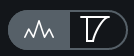
The Maximizer module includes the following views:
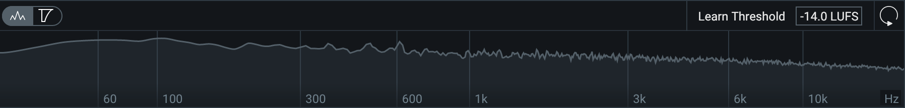
Spectrum Analyzer
Displays the magnitude (amplitude, in decibels) of a signal across the frequency spectrum in real-time. The spectrum analyzer displays the output signal of Ozone.
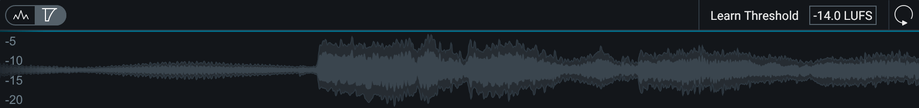
Gain Reduction Trace
Displays a scrolling waveform with a superimposed trace reflecting the amount of gain reduction applied over time.
Controls
The Maximizer includes the following controls:
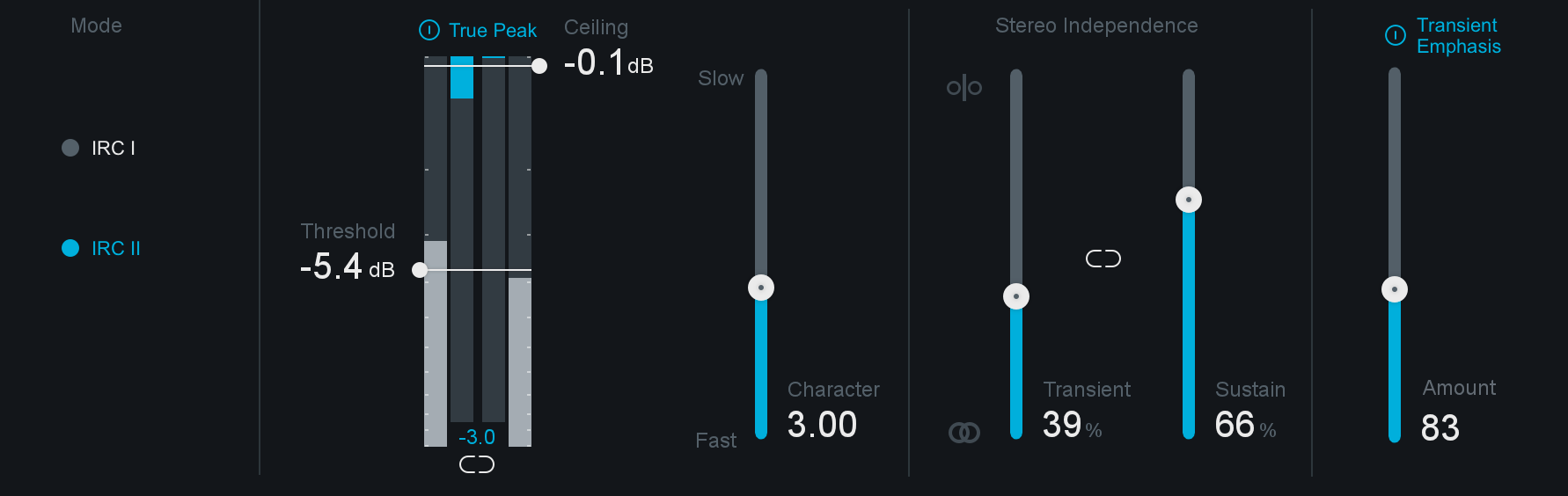
Mode
The Maximizer includes the following Intelligent Release Control (IRC) modes:
- IRC I: Provides intelligent digital loudness maximization of the signal. It does this by analyzing the source material and applying limiting in a psychoacoustically pleasing manner, reacting quickly to transients (to prevent pumping) and reacting more slowly to steady bass tones (to prevent distortion).
- IRC II: Similar to IRC I, but optimized to preserve transients even more, so they sound sharper and clearer in the output signal, even when aggressive limiting is taking place.
Threshold
Set the level at which the limiter will be triggered and adjusts the amount of gain added to the signal to maximize the output level.
Threshold and Maximizer Output
Setting the Threshold to a non-zero value that doesn’t trigger the limiter will still increase the output of the Maximizer. For example if the input level to the Maximizer is peaking at -15 dB and the Maximizer Threshold is set to -4dB, limiting will not occur, but the level at the output of the Maximizer will be peaking at -11dB.
The threshold control includes the following sub-controls and meter:
Threshold Meter
Displays input level and applied gain reduction.
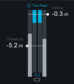
- The two outer meters display input level to the limiter.
- The two inner meters display gain reduction applied by the limiter.
- The text readout at the bottom of the meter displays the current gain reduction amount that is being applied by the limiter.
Ceiling
Adjust to set the maximum output level of the Maximizer.
Threshold and Ceiling Link
Enable to link the Threshold and Ceiling controls. Adjusting either control in linked mode will adjust the other control by the same amount and vice versa.
True Peak
When enabled, the limiter will account for the levels of each digital sample and the levels of the analog signal that will eventually be produced by D/A conversion. This is sometimes necessary, since an analog signal’s peak level can exceed the corresponding digital signal’s peak level by more than 3 dB.
True Peak Limiting & CPU Usage
This option will result in a small increase in CPU usage, but if your mixes are running very hot you may want to enable it to ensure that absolutely no distortion is introduced when your audio is finally run through a D/A converter.
Character
Adjust to customize the overall response time (attack and release times) of the Maximizer. The attack and release times are influenced by the selected Mode. The Character slider ranges from Fast (0.0) to Slow (10.0) in each mode.
Stereo Independence
The Stereo Independence controls represent the next iteration of the Stereo Unlink control in previous versions of Ozone. By default, the Stereo Independence controls (Transient and Sustain) will be linked and set to 0% - mimicking the default settings of the previous Stereo Unlink control.
- Transient Slider: Adjusts how the limiter responds to transient material across channels.
- Sustain Slider: Adjusts how the limiter responds to sustained material across channels.
- Link: Links the Transient and Sustain sliders.
Examples
- Both Sliders set to 100%: It is possible to achieve a louder output from the Maximizer, but this can result in a narrow stereo image. To alleviate the narrowing effect of the Stereo Unlink control, we split this feature into two sliders.
- Sliders independently set to non-zero values: Applies limiting to transient and sustained material separately, based on a level envelope generated from a ratio of the individual channel levels and the entire stereo image.
Transient Emphasis
Enable Transient Emphasis adjustment by clicking the Transient Emphasis power button. Adjusting the Amount control allows you to fine-tune the shaping of transients before limiting takes place. This can be useful for preserving sharper sounds, like drums, while still optimizing loudness.
Transient Emphasis Settings
Using higher amount values for Transient Emphasis will result in more pronounced transients after the limiting process.