Dynamics
Overview
One of the most powerful modules in Ozone is the Dynamics module. You can use this module to shape the dynamics of your mix, with up to four bands of analog-modeled compression, limiting, and expansion. Dynamics is also available as a component plug-in of Ozone 8 Advanced.

Global Controls
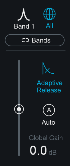
SINGLE BAND/ALL BANDS DISPLAY
Toggles between All Bands view and Single Band view. When Single Band view is selected, you can use the arrows to the left or right of the band icon to cycle through the enabled bands.
LINK BANDS
When enabled, adjustments made to any band control will affect the corresponding control in all other bands.
ADAPTIVE RELEASE
When Adaptive Release is On in the Dynamics module, it will automatically adjust the Release time of the Compressor based on the Peak factor of a signal. If a transient signal is detected, the Release time is scaled to be shorter for less pumping. If a sustained note is detected, the Release time is scaled to be longer for lower distortion.
The Release time is scaled in relation to the Release value set by the user. For example: if you are using the Compressor with the Release time set to 100 ms, the Release time will be automatically adjusted to a value within a range of 20 ms to 200 ms, depending on the type of signal that is being processed.
GAIN
- IN ALL BANDS VIEW: The Gain slider affects the gain of the entire Dynamics module after processing. This is useful, for example, after compressing or limiting to makeup the decrease in volume.
- IN SINGLE BAND VIEW: The Gain slider will affect the output gain of the currently selected band after processing.
AUTO GAIN
When you click the auto button, automatic gain control calculates the RMS levels of both the input and output signals of the Compressor for each crossover band, and then applies the appropriate gain to the output signal to compensate for the difference. This automatically brings audio levels to a level comparable to the unprocessed audio, and acts as a smart “make-up gain” control that adapts to the mix over time. This is also a useful tool for A/B’ing various settings in the multiband Dynamics module without having gain changes affect your perception.
LEVEL DETECTION MODE
The 3 buttons below the threshold input meters control the global level detection mode for the Dynamics module.
- PEAK: When this option is enabled Ozone’s detection circuit looks at peak levels of the incoming signal. In general, this setting is useful when you are trying to even out sudden peaks in your music.
- RMS: When this option is enabled, Ozone looks at the average level of the incoming signal. RMS detection is useful when you are trying to increase the overall volume level without changing the character of the sound.
- ENVELOPE: Envelope mode behaves much like RMS mode, but with some key advantages. Unlike RMS, Envelope mode produces even levels across all frequencies. Additionally, Envelope mode will not produce the aliasing or artifacts that RMS detection can cause.
PARALLEL
Adjust this slider to control the dry/wet mix of direct, unprocessed signal to the processed signal for the current band. This slider is very useful for applying the technique called “parallel compression” where you can mix in a desired amount of unprocessed signal.
Per Band Controls
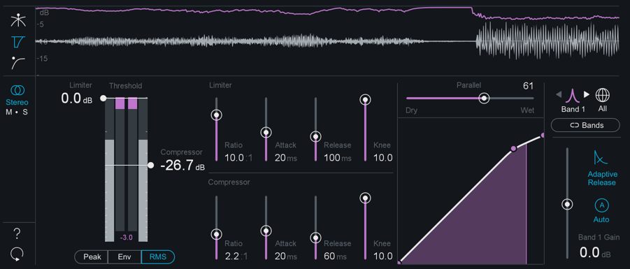
THRESHOLD
Adjust the threshold of the limiter and compressor to set the point where the dynamics processing takes place.
RATIO
Both the Limiter and Compressor have their own ratio control. Higher ratios will result in more extreme compression. When the Compressor or Limter’s ratio is set to a negative number, it will act as an expanders.
ATTACK & RELEASE
Adjust the attack and release controls to set how quickly the dynamics processor reacts to audio that crosses the threshold.
- ATTACK determines how quickly the dynamic processor reacts when the threshold is reached.
- RELEASE determines the amount of time before the dynamics processor returns the level to normal once the signal is no longer above the threshold.
KNEE
Adjust this control to set the desired character of the compression.
- Higher settings result in a “soft knee” setting with a subtler, natural sounding compression.
- Lower settings result in a “hard knee” setting with a more aggressive sounding compression, often used as an intended effect on individual tracks such as kick and snare drum.
Mid/Side Processing
The Dynamics module can operate in either Stereo or Mid/Side operation. See the Mid/Side Processing section for more details.
Meters
The Dynamics module offers 3 different mini-metering views along the top of the controls panel.
CROSSOVER
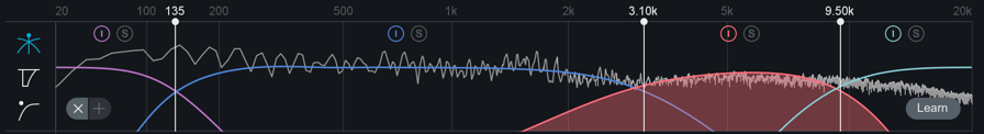
This view displays the multiband information and crossover points for the module. For more information, see the Using Multiband Modules section.
DETECTION FILTER
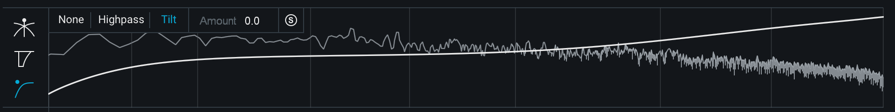
This view allows you to specify the frequency response of the detection circuit used by the dynamics processor, so that it is less sensitive to lower frequencies. This is particularly useful when using the Dynamics module in single-band mode.
You can choose between the following modes:
- None: No filter is applied to the module. The detection circuit is equally sensitive across all frequencies.
- High-pass: A high-pass filter is applied to the module.
You can make the following adjustments to the filter:
- Click the “slope” label to cycle through lter slopes (6, 12, 24, and 48 dB).
- Click and drag the frequency node, on the high-pass filter display to select the frequency of the high-pass filter.
- Tilt: Similar to the THRUST circuit found on API compressors, Tilt mode preserves low frequencies using a high-frequency weighted filter curve. You may adjust the amount of slope in the filter curve by adjusting the Amount value.
For all three of the detection filter modes, click on the small “S” icon to solo the filtered frequency, allowing you to monitor only the signal that the detection circuit is using to trigger the Dynamics module.
GAIN REDUCTION TRACE
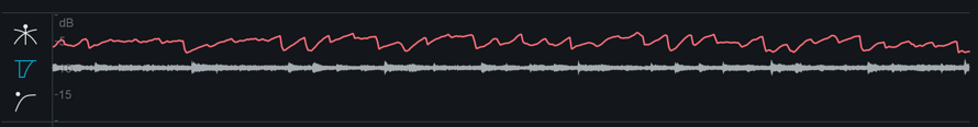
This view offers a scrolling meter that displays the incoming signal’s waveform with a superimposed curve that illustrates the amount of gain reduction taking place in real time.
When using multiband processing, the current selected band’s gain reduction is drawn imposed on a waveform of only that band’s signal. The Gain Reduction Trace can help you to set attack and release controls appropriately and monitor the envelope of gain reduction.
Note: You can adjust the scale on the left by hovering over it and using your mouse wheel. You can also slide the scale by clicking and dragging.
THRESHOLD METER
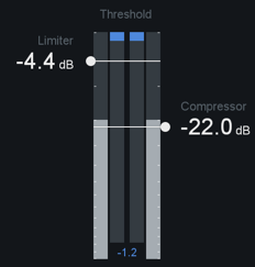
The Threshold meter displays gain reduction as it is taking place with level meters.
Two meters display the levels of the incoming signal, and as gain reduction begins to take place, a gain reduction meter appears in red between the two level bars.
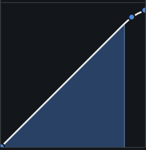
DYNAMIC CURVE METER
This meter shows the input signal (x axis) plotted against the output (processed) signal (y axis). More horizontal compression curves mean the signal is being attened (compressed) more. You can zoom in and out on the meter by clicking the “+” and “-” buttons in the bottom right. The meter features individual nodes for the Limiter ( L ) and Compressor ( C ). These nodes are linked to the Threshold and Ratio controls, and can be used to adjust the curve in a visual way, rather than setting them with the standard controls.