How to Setup Open Loop Boost Control on Modular ECUs

This article describes how to
configure boost control in open loop mode on the Modular ECUs.
In open loop mode, it means that the duty cycle is fixed in
your ECU settings, and whatever boost that generates is what
you get. This is the way many tuners configure boost
controllers because it’s relatively easy to do it this way. It
has its limitations though so let’s talk about basic boost
control hardware first of all.
First, I’m going to look at the mechanical side of boost control; the reason being that often people think that what they need is to learn about the ECU settings, when they don’t really understand the mechanical system they’re controlling. If you do know this well then skip ahead!
We know that exhaust gas comes out of the engine and spins the turbine, which in turn spins the compressor which generates the boost. To regulate the boost, we control how much exhaust is allowed to bypass the turbine through one or more wastegates.
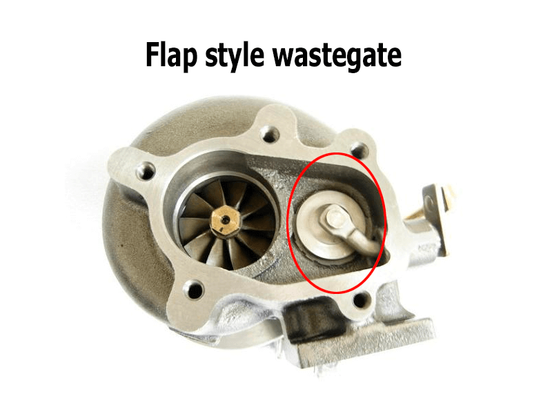
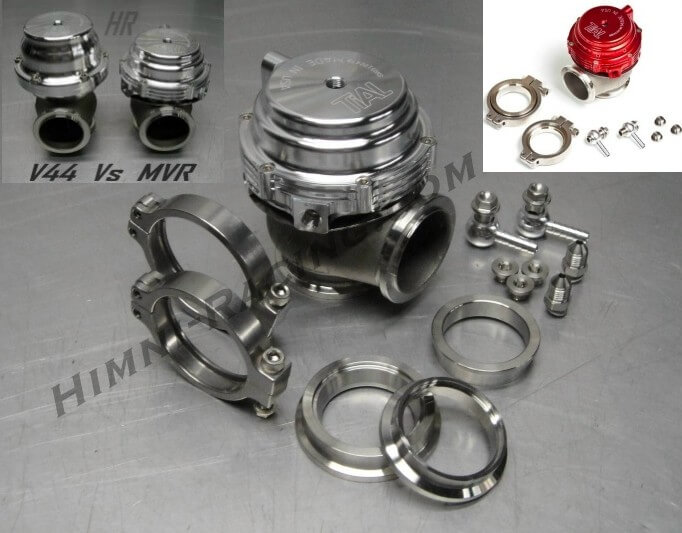
The wastegate is a flap or some other kind of valve which is opened by an actuator. Although it’s possible to design a wastegate like a butterfly so that exhaust pressure does not try to push it open, the two most common types of wastegates I’ve seen have been the flap style as on internally gated turbochargers, where high exhaust back pressures before the turbine will force the door open, and the common aftermarket external gate style where again the exhaust pressure pushes on the disc which forces it to open. This is important to remember.
First, I’m going to look at the mechanical side of boost control; the reason being that often people think that what they need is to learn about the ECU settings, when they don’t really understand the mechanical system they’re controlling. If you do know this well then skip ahead!
We know that exhaust gas comes out of the engine and spins the turbine, which in turn spins the compressor which generates the boost. To regulate the boost, we control how much exhaust is allowed to bypass the turbine through one or more wastegates.
The wastegate is a flap or some other kind of valve which is opened by an actuator. Although it’s possible to design a wastegate like a butterfly so that exhaust pressure does not try to push it open, the two most common types of wastegates I’ve seen have been the flap style as on internally gated turbochargers, where high exhaust back pressures before the turbine will force the door open, and the common aftermarket external gate style where again the exhaust pressure pushes on the disc which forces it to open. This is important to remember.
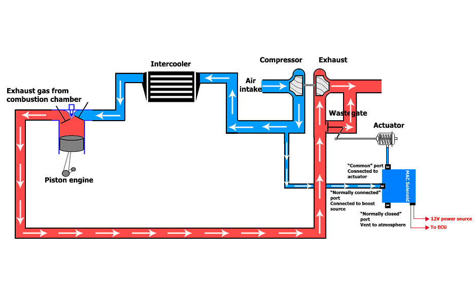
Turbo System
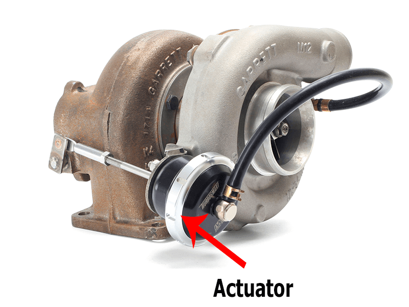
Apart from the exhaust pressure opening the gate, which is an undesired effect, the position of the gate is controlled by an actuator. The actuator has a diaphragm with pressure on either side, and the pressure difference across the diaphragm causes a force, which moves the gate actuator rod and can open the gate. Holding the gate shut is a spring which is normally a compression spring with significant preload.
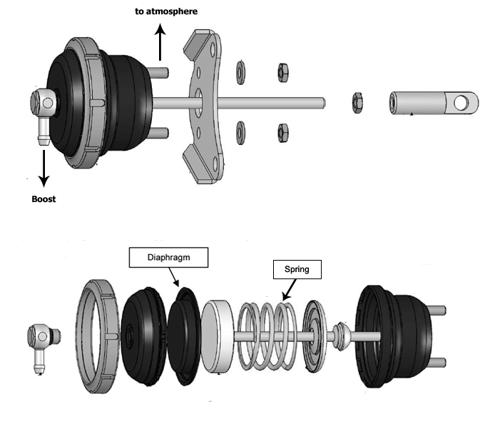
The actuator can either have two pressure ports on it, one for each side of the diaphragm, or just a single port with the other port open to atmosphere.
Single port actuator

Two-port actuator
There are other features of some wastegates such as water cooling, and some like some of the Turbosmart have position sensors as well or they can be added as an option.
Wastegate with water cooling feature
Turbosmart wastegate with position sensor feature
Let’s first consider the most basic type of wastegate system, where you have a single port actuator. The actuator’s pressure port is fed from boosted air from the compressor. At atmospheric pressure, ie zero boost, there’s zero pressure differential across the diaphragm, and the spring holds the gate shut. No exhaust bypasses the turbine, so the turbocharger starts to build boost.
If the turbocharger builds enough boost to increase the airflow through the engine to the point where it can increase the boost further, ie it’s in a position to spool (the RPM is high enough to come on boost and the throttle is open far enough), then the boost will eventually become high enough that the air pressure in the diaphragm is high enough to overcome the spring preload and the actuator rod will start to move. The pressure at which the air pressure force equals the preload in the spring, and from then on it starts to move, is sometimes called the “cracking” pressure because it’s where the wastegate cracks open. Usually the spring will be described by this pressure, for example a 10 PSI spring or a 1 bar spring.
As the boost increases more, the spring is compressed further and the wastegate opens further, until a point where so much exhaust is bypassing the turbine that it can’t build any more boost, and boost is now stable at this point. Note that this will be higher than the cracking pressure because the gate has had to move further to reach an equilibrium point.
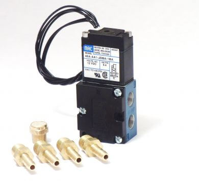
There are multiple ways to control the boost on such a system, but we’ll only talk about the 3-port method. In this system you have a 3-port valve under ECU control. We use the Mac valves. The “common” port on the Mac valve connects to the actuator, the “normally connected” port connects to the boost source and the “normally closed” port is allowed to vent to atmosphere.
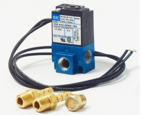
3 way solenoid Mac valve
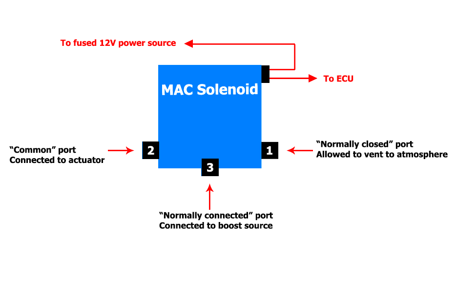
Mac valve port functions
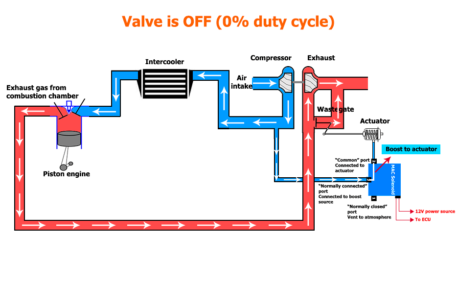
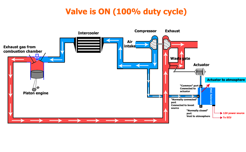
In that way, when the valve is switched off, it just connects the boost source straight to the actuator, and the amount of boost you get is determined by the spring. When the valve is turned on, the boost source is blocked off and the actuator vents to atmosphere, so you get an unlimited amount of boost. By pulse width modulating the valve, you can control it to anywhere in between.
For example if you have a 10 PSI spring, you can achieve 20 PSI of boost by pulse width modulating the valve at 50% duty cycle. At 50% duty cycle it means that half of the time, the actuator sees the 20 PSI from the compressor exist, and the other half of the time it sees atmospheric pressure which is zero boost – so the average works out to be 10 PSI which is what the actuator is trying to regulate to. If you set the duty cycle to 25%, then one quarter of the time it would see atmospheric pressure and three quarters would see boost, so that means you’d end up with 13 PSI boost . Normally you’d PWM the solenoid at about 30 Hz.

Now, let’s look at some undesired effects of this system, limitations and so on, so that you can spot them when they occur.
The first I mentioned before; the exhaust back pressure pushes the door open. The force exerted by a pressure is the pressure times the area. So unless the diaphragm is very large compared to the wastegate, then exhaust back pressure is going to have an effect on boost. In many cases it will limit the amount of boost you can run, because even with the solenoid at 100% or leaving the hose off the actuator all together, once the boost reaches a certain level, the turbo will need a certain amount of exhaust pressure to create the boost and that pressure will force the door open, so it will be self limiting. So this limits the amount of boost you can practically run in an internally gated, factory style turbocharger. It also means that if you run a constant duty cycle, the boost will normally drop off to some extent as RPM increases, due to the backpressure increase at higher speeds (the compressor has to spin faster to make the same boost at higher RPM because the engine is hungrier, so the turbine has to spin faster also).
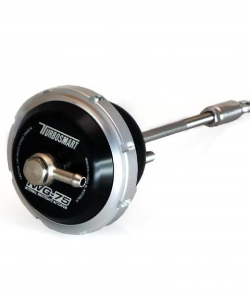
Turbosmart have come out with a replacement for the factory actuator though, called the IWG. It’s similar in construction to a proper actuator from an external gate, but it’s packaged so it can be used as an upgrade for factory style, internally gated turbochargers. The big advantage of this over the standard actuators is that they can have larger diaphragm area than the factory actuator, which makes the behaviour less dependent on exhaust back pressure. This makes the boost pressure more stable and predictable, and also increases the maximum amount of boost you can run.
A common mistake, in my opinion, that people make is to get the pressure source for the boost control from the inlet manifold, rather than from the compressor exit. We know that whichever pressure the actuator sees is the pressure it will attempt to regulate to because that’s all the information it has. Consider a part throttle condition where the driver does not want the full torque available. If the system is set to produce 10 PSI of boost, and the actuator gets its pressure reference from the compressor exit, then we will have 10 PSI before the throttle body, and less after the throttle body, for example zero boost. This is what the driver says that he or she wants, by only applying part throttle.

Connecting the boost pressure source on the intake manifold
If the actuator reference is taken from the manifold instead of the compressor exit (or some other point before the throttle), then it means that the turbo will need to work extra hard because the actuator will keep the gate shut until it sees 10 PSI in the manifold. So the turbo might be making say 20 PSI of boost, but because of the partial throttle condition we only see 10 PSI in the manifold. This has two problems:
- It makes it harder for the driver to control the torque, since whatever he’s doing with the pedal will be undone to some extent by the action of the actuator and wastegate
- It could result in an overspeeding condition where if you put your foot down afterwards, you would get a boost spike because the turbo is spinning too fast.
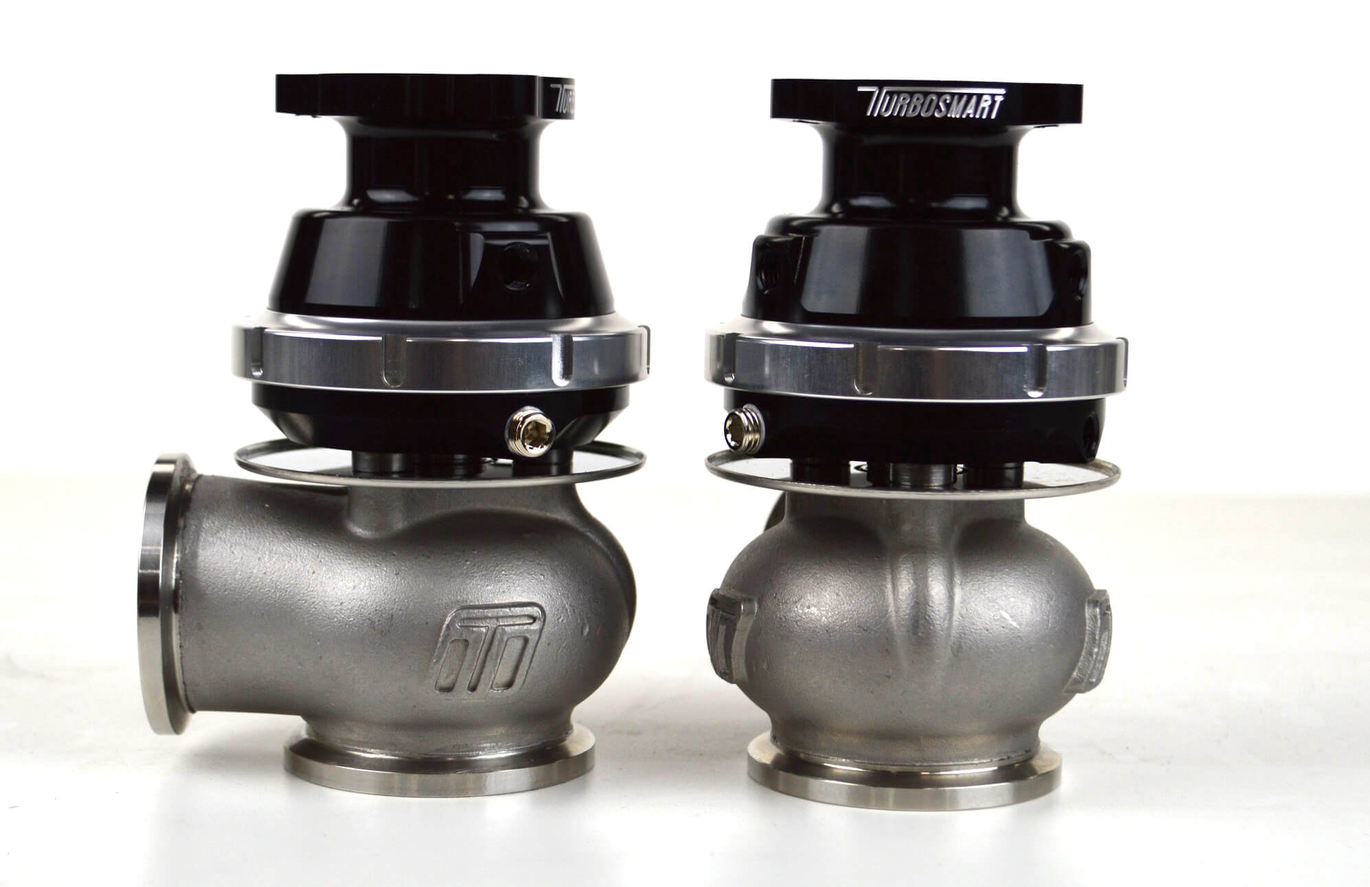
Turbosmart also now have a dual port version of the IWG, so rather than having one side of the diaphragm open to the atmosphere, both sides of the diaphragm have ports on them. With a dual port actuator, the connection method is usually different. The standard way is to connect the boost pressure to the “normal” of the actuator, ie the one which you increase the pressure to open the gate. Then the second port of the actuator, which holds the gate shut, goes to the “common” of a 3-port valve. The “normally connected” port on the 3-port valve vents to atmosphere, so in the normal condition the actuator connection is the same as a single port actuator. When the solenoid is activated though, the “normally closed” port is connected to the pressure source and then the actuator sees boost pressure on both sides.
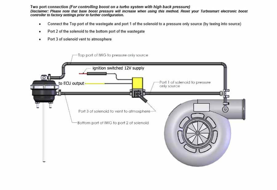
The mathematics is the same as the single port actuator, but it means that there’s more pressure available to force against the back pressure forcing the flap open, and therefore the boost regulation at higher back pressure conditions is better.
This theory can also be applied to an external wastegate. External gates normally have much bigger diaphragms, but they also usually have larger gates. In this case the “bottom” port is the one which gets the pressure to open the gate, and the “top” or the dome gets the pressure to close the gate.
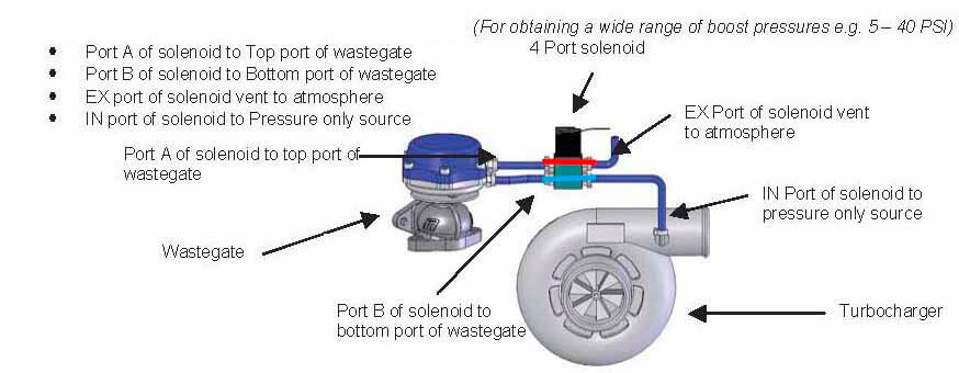
There is a third connection type, which uses a 4-port Mac valve. Conceptually it’s the same as a 3-port valve, and if you have 2 x 3-port valves you can achieve the same thing so I’ll just describe it as 2 x 3-port valves here.
Four-port Mac valve
In this configuration, the top and the bottom of the actuator each connect to the common ports of their own 3-port valves. The bottom one’s normally connected port connects to the boost source, and the normally closed port vents to atmosphere, just as with a single port actuator. The top port’s connection is opposite – the normally connected port connects vents to atmosphere and the normally closed port connects to the pressure source.

When the solenoid is turned off, the bottom of the actuator sees boost, and the top sees atmospheric pressure so you end up with the boost set by the spring pressure. However when it’s turned on, the bottom sees atmospheric pressure and the top sees boost which holds the gate shut. Because you don’t have the boost on the other side of the diaphragm, this can hold shut against substantial exhaust back pressure even with a spring that isn’t that strong.
A typical single 3-port valve system can usually only hold up to about double the spring pressure level of boost with any degree of control, but a 4-port system as described here can hold much higher. The limiting factor is when the exhaust back pressure ends up being more than or close to the spring pressure plus your boost pressure; in that case the only way to do it is with an external pressure source like a CO2 bottle.
Now that we’ve talked about the mechanical system, we can talk about how the ECU works out the duty cycle in the basic duty cycle mode.
The first thing to understand is that there are many variables that the ECU can use to control the boost level. The ECU can determine boost by the main boost map, but can also have corrections for external switch inputs, the current transmission gear ethanol content and “push to pass” or “scramble boost”.
All the settings are found in the Tuning – Air, boost control section in the software.
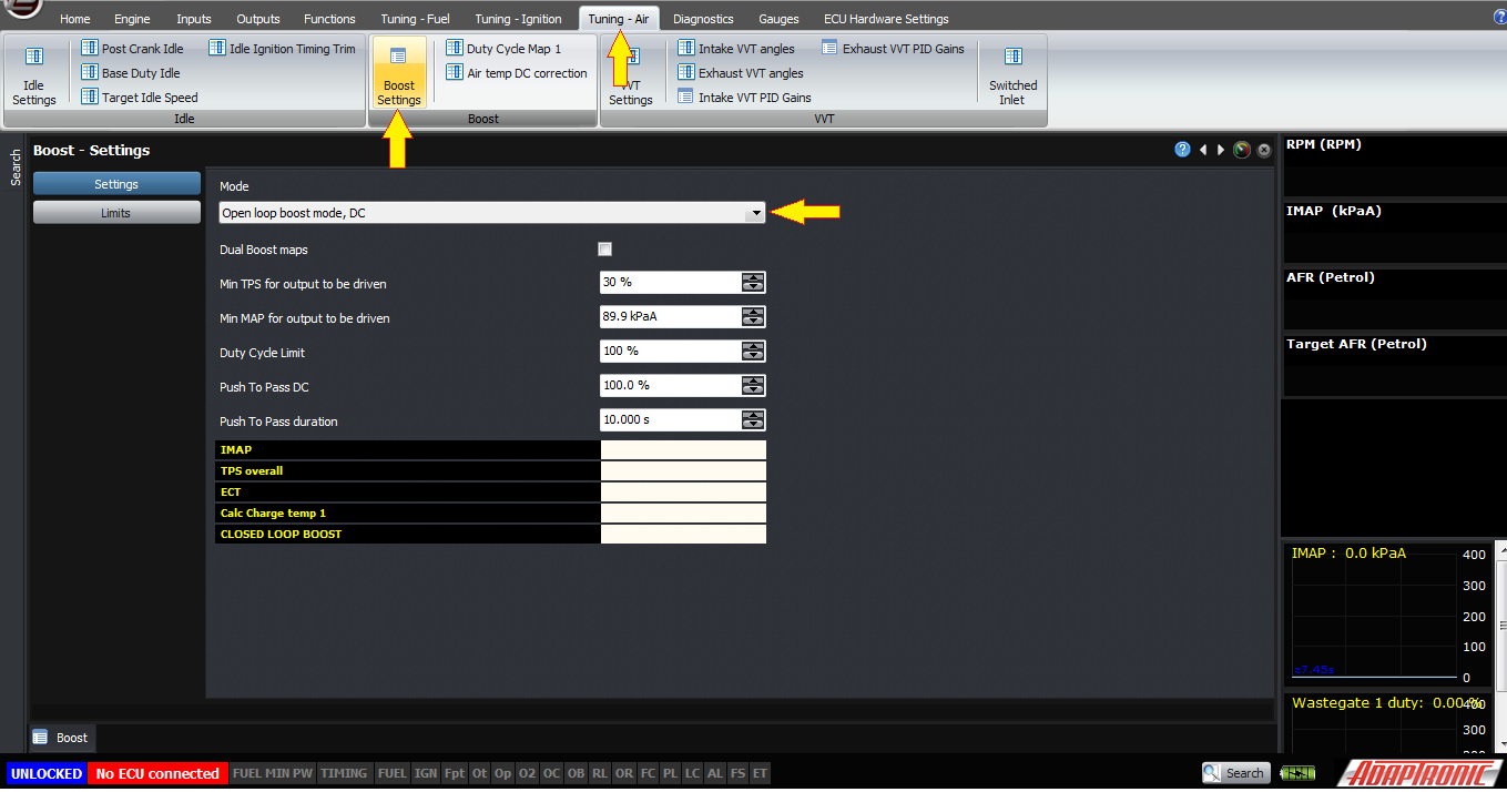
Firstly, the mode you should select if you want to do it based on the duty cycle only, is the “Open loop boost mode, DC”
Secondly, you can choose whether to enable “dual boost maps” or not. Dual boost maps allow you to have two separate boost maps, which is the duty cycle vs throttle position and RPM. If you don’t enable this, then you can still have a switch to select different boost levels and I’ll explain that in a bit.
If you do enable dual boost maps, then you will have two duty cycle maps in the settings. To enable the second map, you must select a digital input as boost setting 1, and then when that input is triggered then the ECU will switch over to the second boost map.
Secondly, the ECU will only activate the wastegate control output once the conditions of minimum TPS and MAP are met, so set this to values like slightly on boost or slightly on vaccum, and TPS of say 30% so it’s not always driving the valve during cruise conditions. Of course you could just tune this in the map anyway.
Duty cycle limit is a percentage you can manually enter to be able to limit the duty cycle of the output. This is really put in there for convenience of testing and safety; there’s no logical reason to use it in a final system.
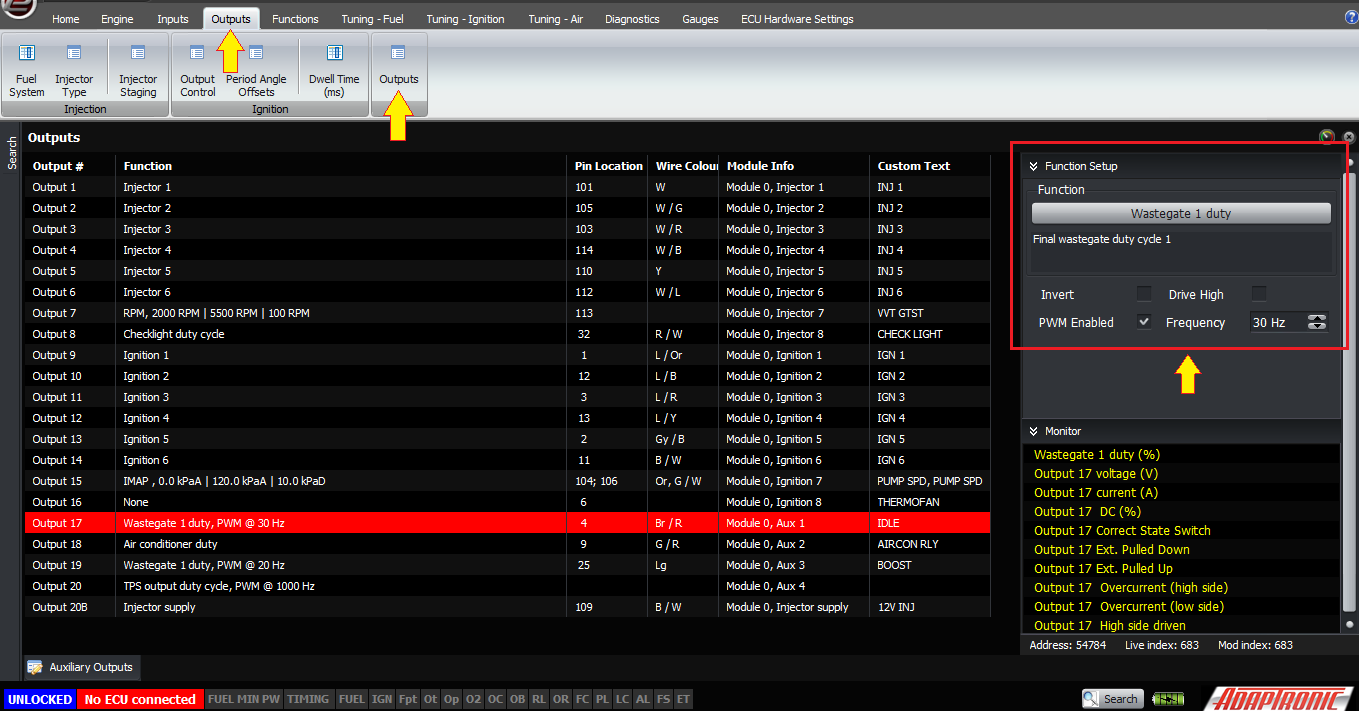
You’ll need to set up an output to drive the 3 or 4- port valve. This should be an auxiliary output, or on the Modular ECUs you can use an unused injector output instead. Just as with driving other PWM solenoid valves, the other side of the solenoid should connect to an ignition switched, 12V supply. The corresponding output in the ECU should be configured as Wastegate 1 duty, PWM at 30 Hz for most valves. You can run two or four valves off a single output, but the reason you would use the Wastegate 2 duty is if you’re doing dual closed loop boost control, for example on a 300ZX or a V12 with two separate turbos and two separate inlet manifolds.
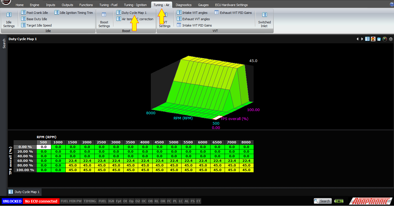
Once you’ve set up those initial settings, you can adjust the duty cycle map. In the single map mode, you’ll just have the duty cycle map 1, where the axes are throttle position and RPM. Just like the other maps in the Modular ECUs you can insert and remove columns and rows as you like.
There’s another map, which hopefully you won’t need to adjust, but it’s there in case you do, and it’s a correction for air temperature. In theory this map should be at zero everywhere but if you find that there’s an air temperature sensitivity which you want to tune out, which usually means generating more boost for the same duty cycle at lower air temperatures, you can put in a slope with negative values at lower air temperatures.
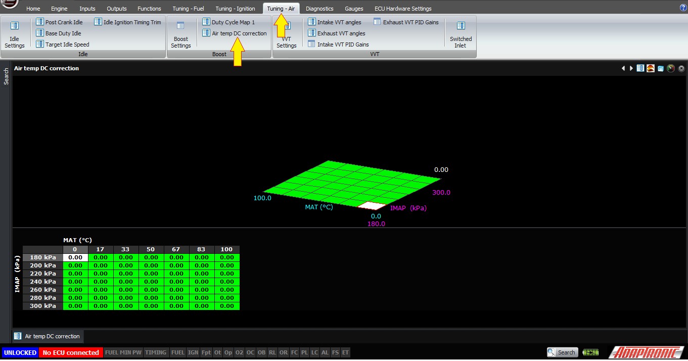 I
know that some people use a basically open loop boost control
strategy, but with a map where they can adjust a correction
based on manifold pressure. You can also do that using this
table if you like. This is similar to using a
proportional-only controller, and just as with a PID closed
loop system, you can get it to hunt if you’re not careful and
make it too aggressive.
I
know that some people use a basically open loop boost control
strategy, but with a map where they can adjust a correction
based on manifold pressure. You can also do that using this
table if you like. This is similar to using a
proportional-only controller, and just as with a PID closed
loop system, you can get it to hunt if you’re not careful and
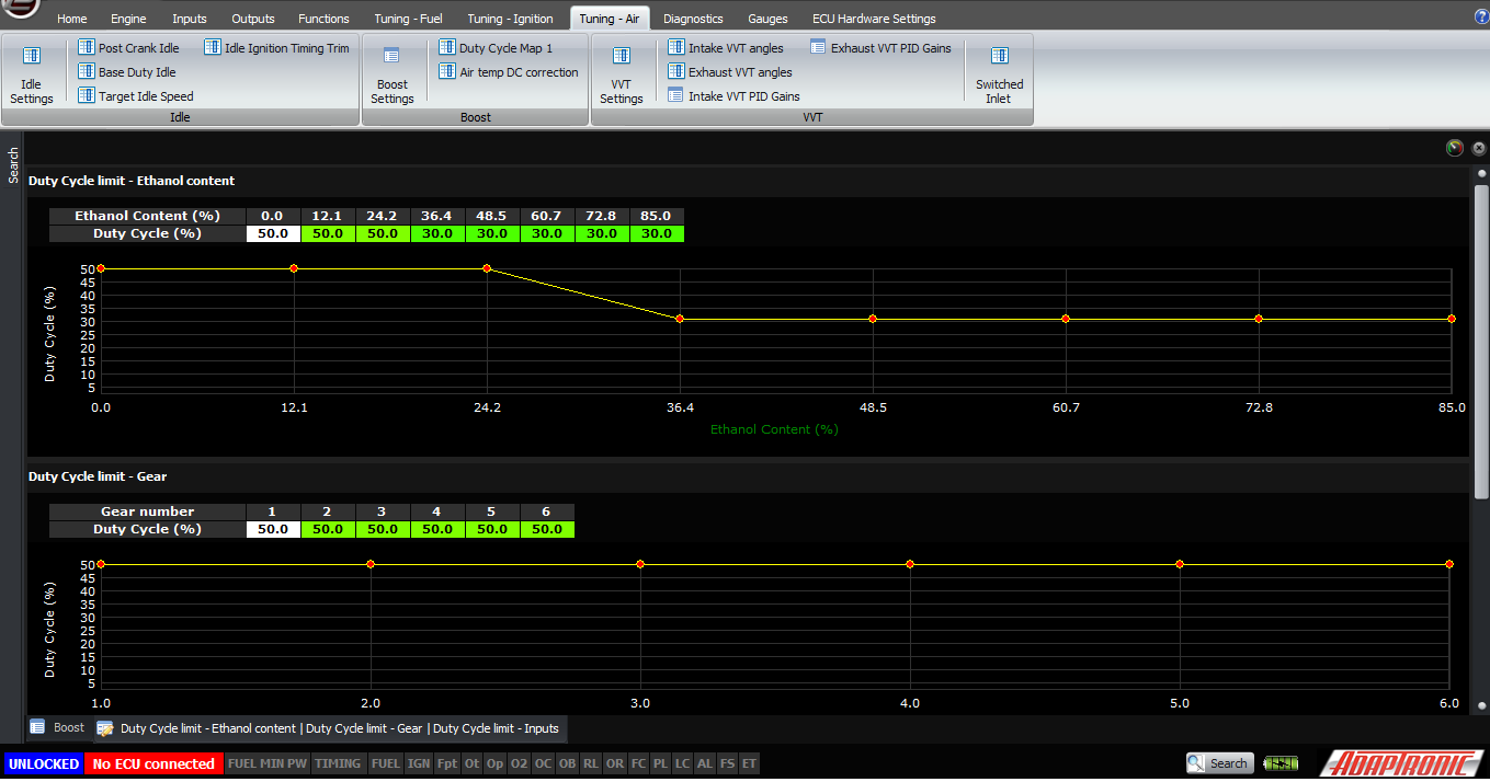
make it too aggressive.The next item to consider is boost limits. These are limits to the duty cycle based on circumstances in which you want to run less than full boost. Each of these limit types can be enabled separately.
Ethanol content is the first one, and this is a simple 2D table with ethanol content as a percentage from 0 to 100% as the input variable, and the value that you enter is the duty cycle to which the output will be limited. For example if you put 30 in this table at the current ethanol percentage, then even if you have 50% in your main map, you will only have a 30% duty cycle output (except in the case of push to pass which I’ll describe soon).
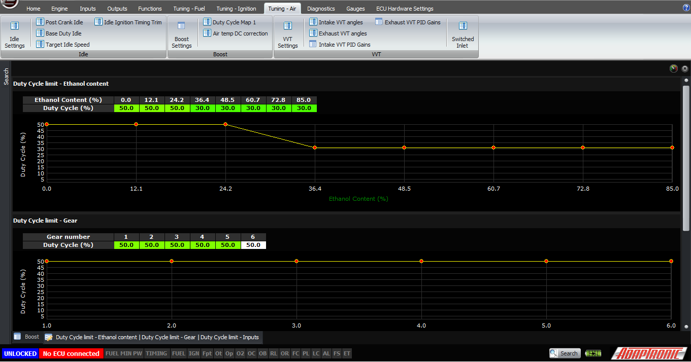
The second one is the gear based duty cycle limit – in this case the input variable is the gear number, eg 1, 2, 3, 4, 5, 6 and the value in the table is the maximum duty cycle for each gear. If you have a limit in this table and the ethanol table then both limits will apply, which means that you’ll get the lower of the two.
The final limit is based on digital inputs for boost selection.
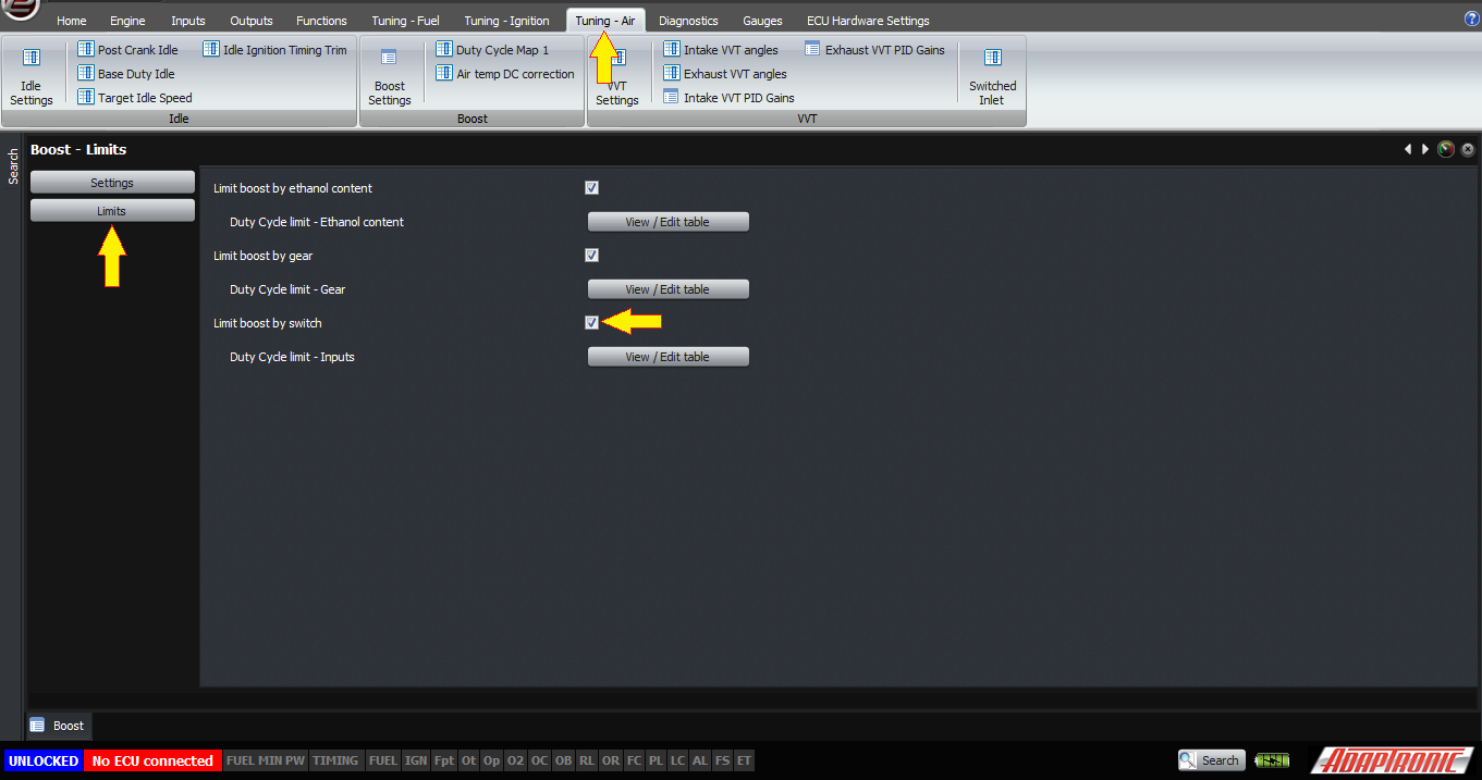
The digital input value is from 0 – 3. This allows for 4 different boost settings via 2 digital inputs, and it’s easy to set up using a 4-position, 2-pole rotary switch.
To set this up, you will need 2 digital inputs. One must be set as Boost Setting 1, and the second must be set as Boost Setting 2.
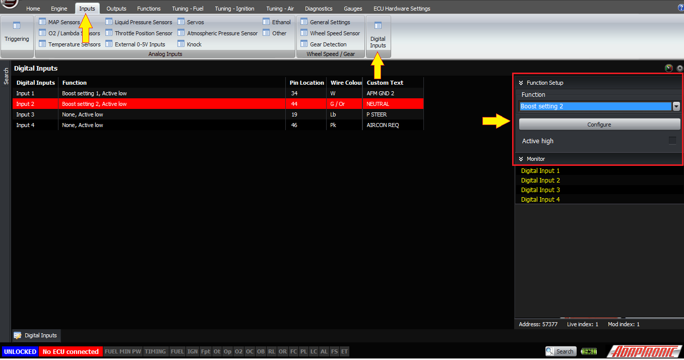
The following input configurations give the following boost switch numbers:
- Both inputs off (inactive, usually means open circuit) – 0
- Boost setting 1 active (usually that means connected to ground) – 1
- Boost setting 2 active – 2
- Both boost setting inputs active – 3
Note that on some systems, having a fixed duty cycle might give a problem where the boost is not constant with RPM, despite that being your intention, and in that case you would be better off using a target boost mode which will be covered in a different article.
The final setting you have available is the “push to pass” setting, sometimes called “scramble boost”. It’s a bit like the proton pill that Roger Ramjet used to take which gives him the strength of 20 atom bombs for a period of 20 seconds, but in this case you can define the duration, and you can also specify the duty cycle that’s active for this push to pass time. Note that the push to pass function overrides all of the limits except for the duty cycle limit.

Thank you very much!
©2018 Adaptronic