Target Boost Modes on Modular ECUs

This article describes using target
boost modes in the Modular ECUs.
Firstly, let’s talk about the reason we do it this way. What we found with the Select ECUs was that the majority of people were happy to run an open loop duty cycle, but a few wanted to do closed loop functions also.
Also, people wanted different boost levels under different conditions. For example with different ethanol content, or an external input switch to select a different boost level, or in different gears. The vast majority of people wanted the switch to hold a certain boost level, which if you have a well configured mechanical system, will equate to a fairly constant duty cycle, but in other cases this doesn’t happen and you end up with boost creep or taper as RPM increases.
If you do want to do closed loop, then as well as having different base duty cycles under these different conditions, we need to have different boost targets as well, or run in open loop mode.
This means that if you want to change one of these settings, you need to change 2 values; one is the target boost and the second is the duty cycle, not to mention the creep or taper behaviour discussed earlier.
So with the Modular ECU we’ve decided to get away from that, and instead we have two modes of running the boost control. One is open loop duty cycle, which has already been described in the open loop duty cycle article. The second is target boost, which is the topic of this article.
In target boost mode, instead of working out a duty cycle from all the maps, we instead work out a target MAP. So the basic boost map, instead of being a duty cycle map, instead becomes the target MAP in kPa, or if you prefer PSI an inHg, it’s represented as gauge pressure but offset from 1 standard atmosphere so it still represents MAP. All the limits, for example the ethanol, the switch input and the current transmission gear all become MAP limits now rather than duty cycle limits, and push to pass is now a new (higher) MAP setting rather than duty cycle.
The ECU then calculates the target MAP, based on all these functions, using the same logic as the open loop boost control uses to calculate the duty cycle.
This target MAP then becomes the target for closed loop PID, but the ECU also needs a way to work out the duty cycle from this MAP target.
Currently there are 2 ways to do this.
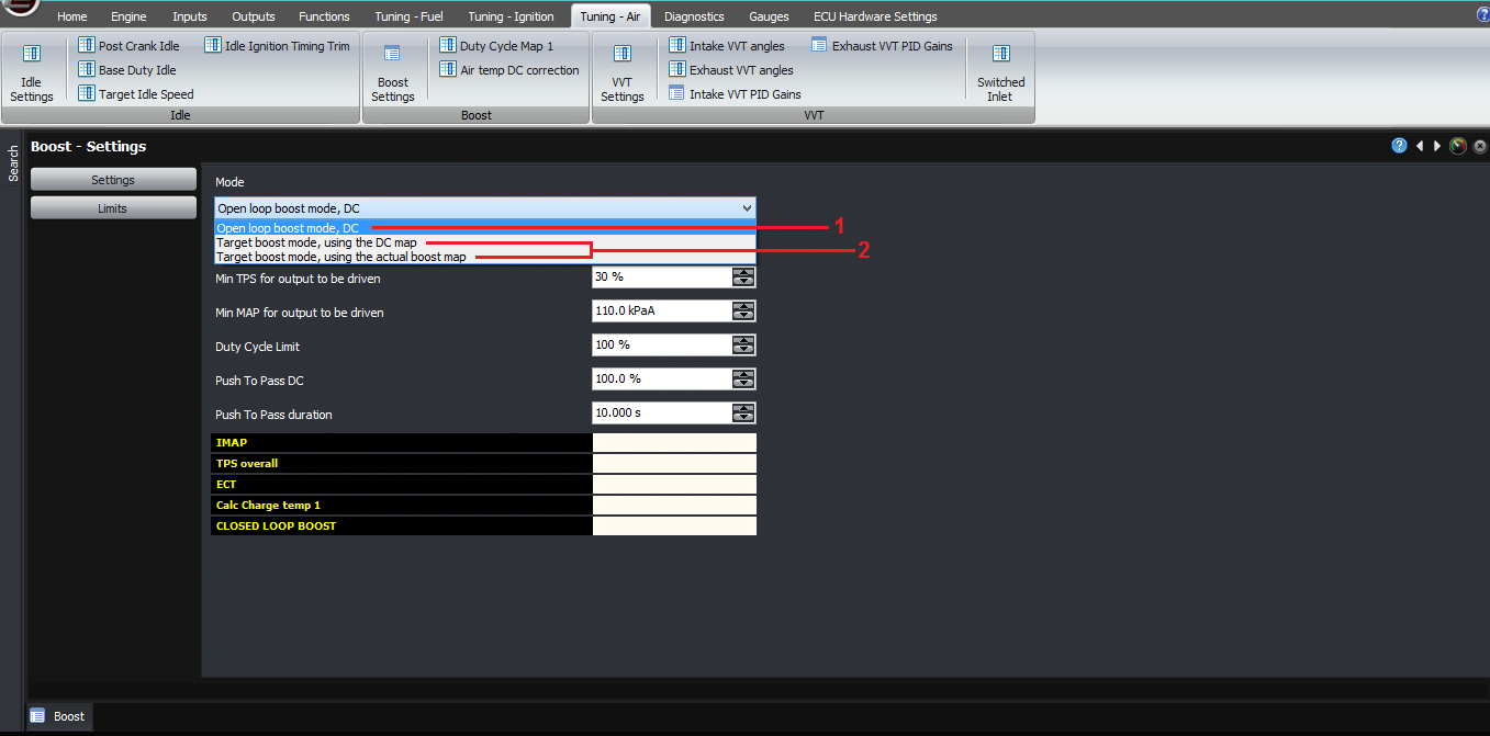
The first is the more traditional way, and in it you have a 3D map of RPM on one axis, and target MAP on the other. The value of the cell in the map is the duty cycle required to achieve that target boost at the given RPM. This means it has to be tuned, which will be pretty fiddly. So it’s here for people that are used to this technique from other ECUs but we don’t recommend it.
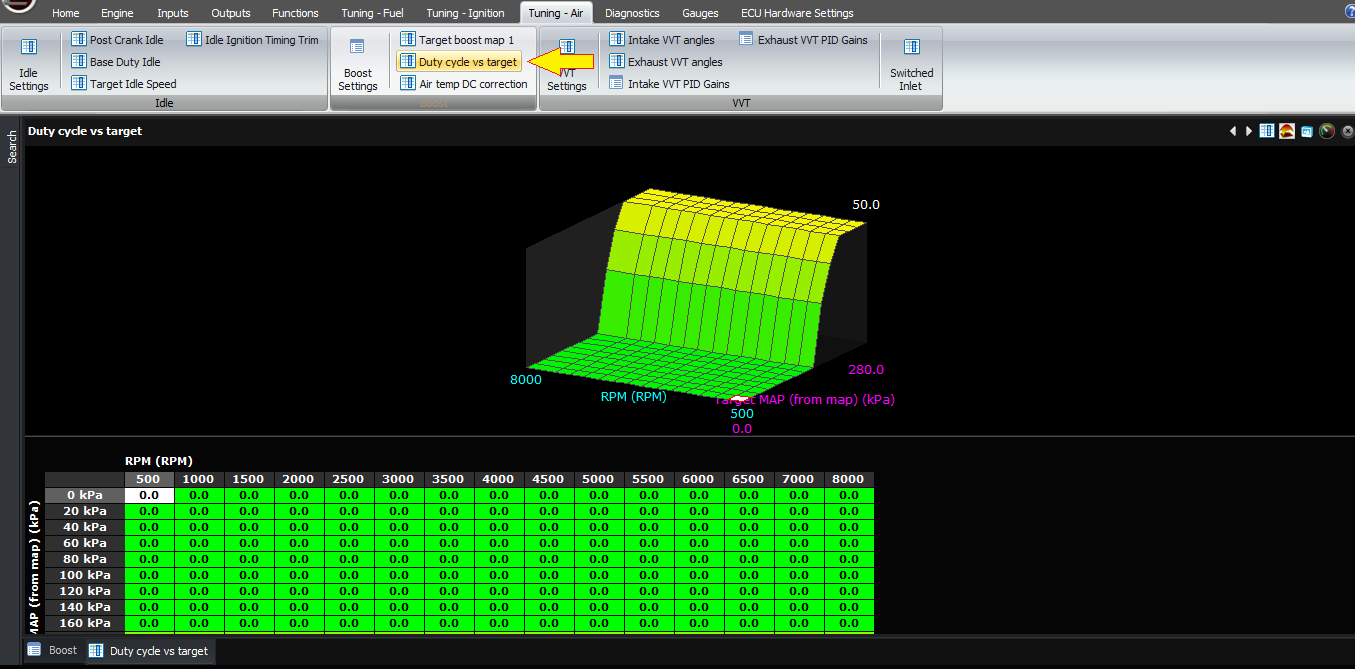
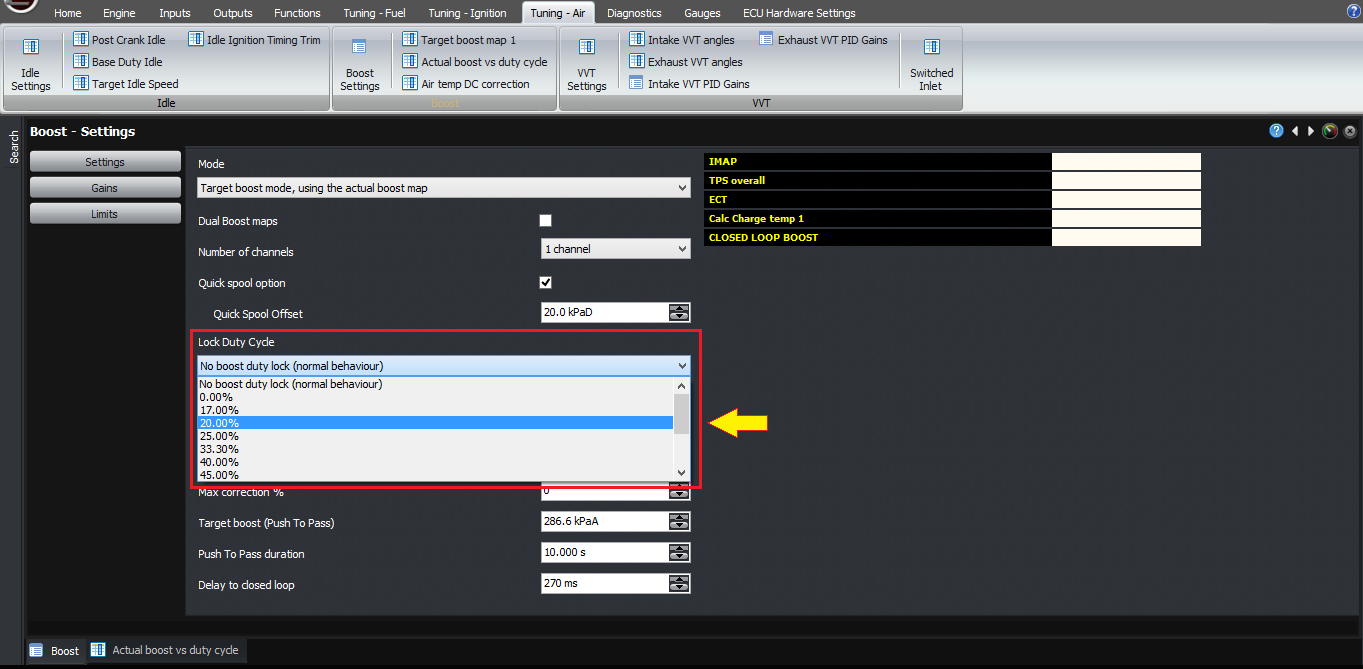
The other way is to instead have an actual boost map, where the two axes are RPM across, and duty cycle going down. The map then contains the actual boost achieved (represented as MAP) with the given RPM / duty cycle combinations. You can use the “lock duty cycle” function in the boost control settings to force the ECU to use a particular duty cycle on the actuator, and then as you increase the RPM through the rev range, the ECU will record the actual boost achieved into this table. Therefore, to set the table, all you need to do is set the axis points and then go through each duty cycle in turn and allow the ECU to sample it as you do a power run.
When you then disable the “lock duty cycle” function, the ECU then works out the target MAP or boost as described earlier. The ECU goes through the current column based on the RPM to find out what the duty cycle would need to be to achieve the target MAP. This could be described as reverse-interpolation. The ECU then uses this for the base duty cycle.
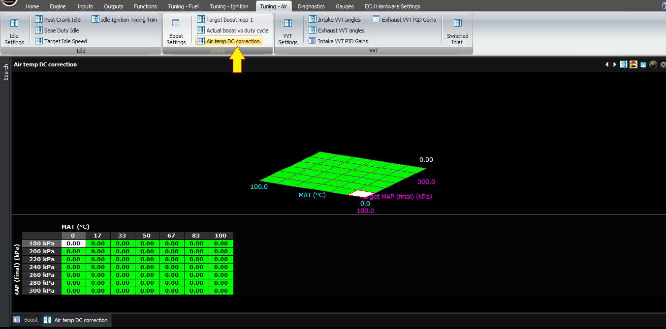
After the ECU has the base duty cycle, it applies the air temperature correction map as described earlier, however the axis is now the target MAP rather than the measured MAP. Therefore you can’t use it to do a semi-closed loop function (but you have a PID controller with which to do that).
Now the ECU has a base duty cycle and a target. Let’s look at the other functions it can perform.
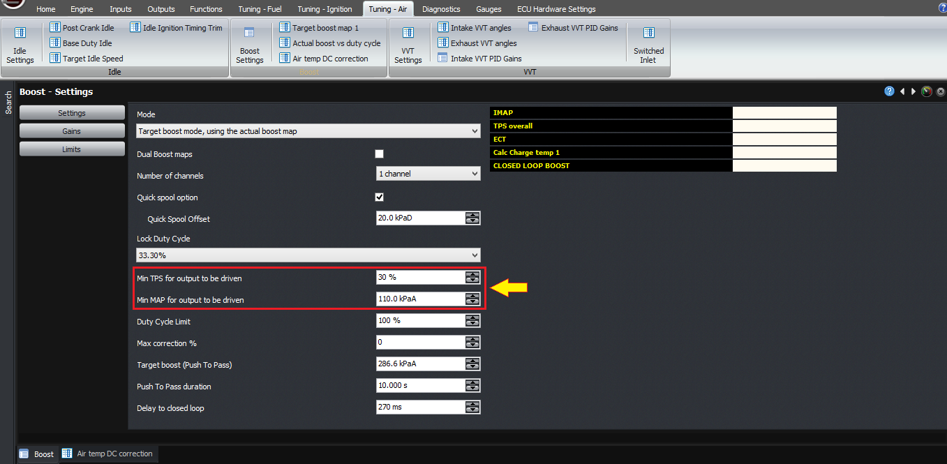
First of all, the other conditions for driving the solenoid output, such as minimum MAP and minimum TPS, still apply, so we need to bear that in mind.
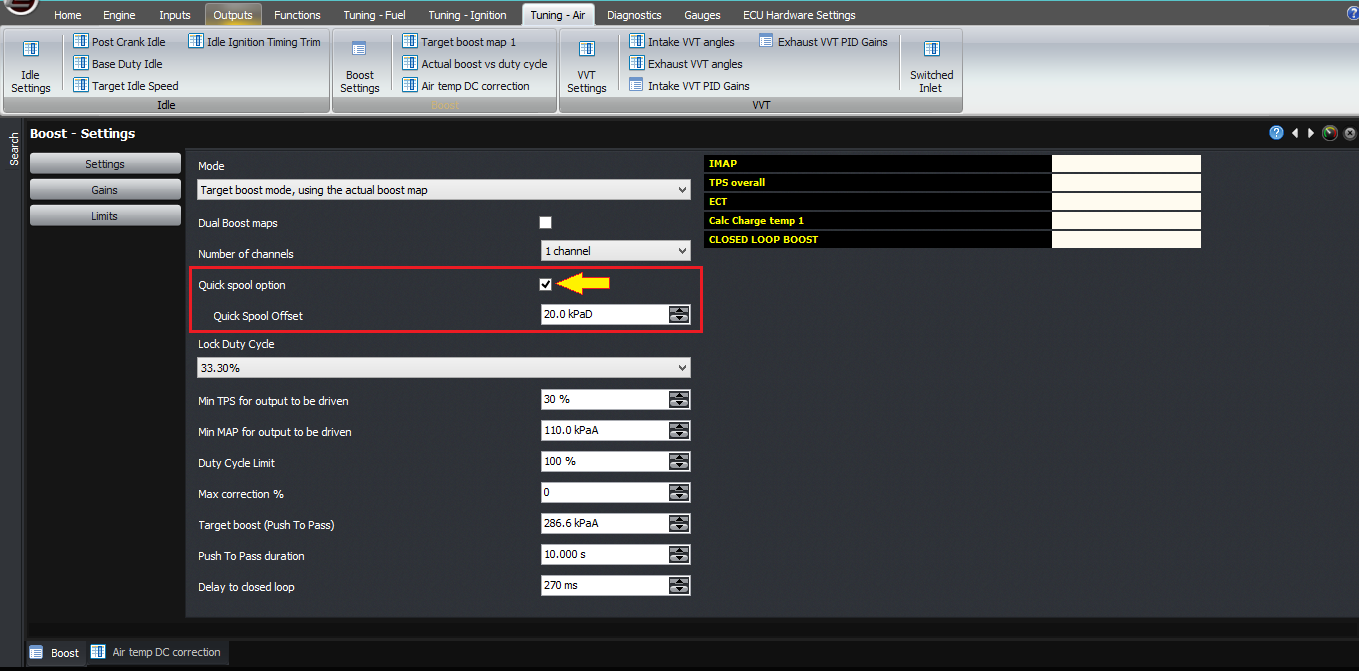
Next, there is a quick spool function. If the mechanical setup is tight then this should have no effect but nothing is perfect, so here it is. When the MAP is less than the target MAP minus the quick spool offset, the output is held on at 100% duty cycle, to help the turbo spool up more quickly. The offset is there to allow you to switch over to the standard boost control duty cycle before the turbo overspeeds and causes a boost spike condition; so you’d normally set the offset to a value like 15 kPa or 2 PSI, more if your turbo comes on to boost very suddenly.
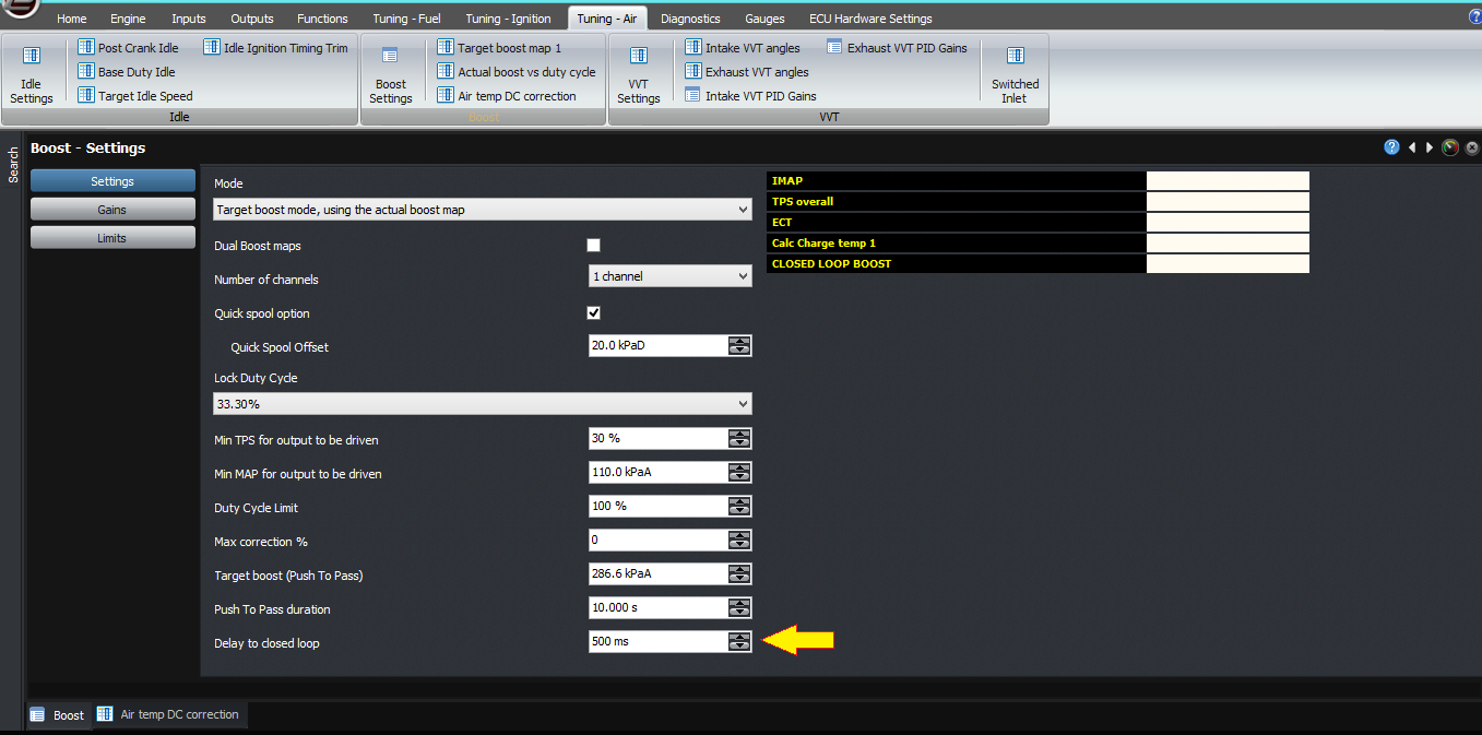
After that, there is a time allowed before the ECU will go into closed loop boost control. This is to avoid integrator wind-up effects; basically it allows the turbo to reach an equilibrium speed. A typical value would be 500 milliseconds.
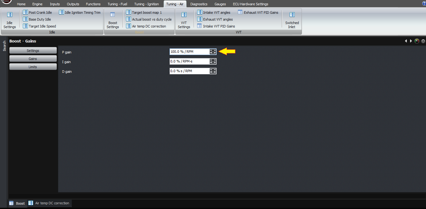
Then you have the PID gains, for if you want to run closed loop. If you want to run open loop, just set these to zero. The gains are in percent-percent; so as an example, if your target is 210 kPa, and the actual MAP is 200 kPa, that means you’re 10 kPa too low. If you enter a proportional gain of 100%, then that will give you +10% duty cycle correction on the idle valve. So in practice you need numbers smaller than this unless you have a very small wastegate spring.
Finally, in terms of diagnostics, the best way is just like fuel tuning – it should be pretty much right in open loop before you try setting up closed loop. So set the PID gains to zero initially and work your way upwards. Remember any integrator term you have will possibly lead to integrator wind-up issues so try to get as much working as possible off the P term.
Thank you!
Firstly, let’s talk about the reason we do it this way. What we found with the Select ECUs was that the majority of people were happy to run an open loop duty cycle, but a few wanted to do closed loop functions also.
Also, people wanted different boost levels under different conditions. For example with different ethanol content, or an external input switch to select a different boost level, or in different gears. The vast majority of people wanted the switch to hold a certain boost level, which if you have a well configured mechanical system, will equate to a fairly constant duty cycle, but in other cases this doesn’t happen and you end up with boost creep or taper as RPM increases.
If you do want to do closed loop, then as well as having different base duty cycles under these different conditions, we need to have different boost targets as well, or run in open loop mode.
This means that if you want to change one of these settings, you need to change 2 values; one is the target boost and the second is the duty cycle, not to mention the creep or taper behaviour discussed earlier.
So with the Modular ECU we’ve decided to get away from that, and instead we have two modes of running the boost control. One is open loop duty cycle, which has already been described in the open loop duty cycle article. The second is target boost, which is the topic of this article.
In target boost mode, instead of working out a duty cycle from all the maps, we instead work out a target MAP. So the basic boost map, instead of being a duty cycle map, instead becomes the target MAP in kPa, or if you prefer PSI an inHg, it’s represented as gauge pressure but offset from 1 standard atmosphere so it still represents MAP. All the limits, for example the ethanol, the switch input and the current transmission gear all become MAP limits now rather than duty cycle limits, and push to pass is now a new (higher) MAP setting rather than duty cycle.
The ECU then calculates the target MAP, based on all these functions, using the same logic as the open loop boost control uses to calculate the duty cycle.
This target MAP then becomes the target for closed loop PID, but the ECU also needs a way to work out the duty cycle from this MAP target.
Currently there are 2 ways to do this.
The first is the more traditional way, and in it you have a 3D map of RPM on one axis, and target MAP on the other. The value of the cell in the map is the duty cycle required to achieve that target boost at the given RPM. This means it has to be tuned, which will be pretty fiddly. So it’s here for people that are used to this technique from other ECUs but we don’t recommend it.
The other way is to instead have an actual boost map, where the two axes are RPM across, and duty cycle going down. The map then contains the actual boost achieved (represented as MAP) with the given RPM / duty cycle combinations. You can use the “lock duty cycle” function in the boost control settings to force the ECU to use a particular duty cycle on the actuator, and then as you increase the RPM through the rev range, the ECU will record the actual boost achieved into this table. Therefore, to set the table, all you need to do is set the axis points and then go through each duty cycle in turn and allow the ECU to sample it as you do a power run.
When you then disable the “lock duty cycle” function, the ECU then works out the target MAP or boost as described earlier. The ECU goes through the current column based on the RPM to find out what the duty cycle would need to be to achieve the target MAP. This could be described as reverse-interpolation. The ECU then uses this for the base duty cycle.
After the ECU has the base duty cycle, it applies the air temperature correction map as described earlier, however the axis is now the target MAP rather than the measured MAP. Therefore you can’t use it to do a semi-closed loop function (but you have a PID controller with which to do that).
Now the ECU has a base duty cycle and a target. Let’s look at the other functions it can perform.
First of all, the other conditions for driving the solenoid output, such as minimum MAP and minimum TPS, still apply, so we need to bear that in mind.
Next, there is a quick spool function. If the mechanical setup is tight then this should have no effect but nothing is perfect, so here it is. When the MAP is less than the target MAP minus the quick spool offset, the output is held on at 100% duty cycle, to help the turbo spool up more quickly. The offset is there to allow you to switch over to the standard boost control duty cycle before the turbo overspeeds and causes a boost spike condition; so you’d normally set the offset to a value like 15 kPa or 2 PSI, more if your turbo comes on to boost very suddenly.
After that, there is a time allowed before the ECU will go into closed loop boost control. This is to avoid integrator wind-up effects; basically it allows the turbo to reach an equilibrium speed. A typical value would be 500 milliseconds.
Then you have the PID gains, for if you want to run closed loop. If you want to run open loop, just set these to zero. The gains are in percent-percent; so as an example, if your target is 210 kPa, and the actual MAP is 200 kPa, that means you’re 10 kPa too low. If you enter a proportional gain of 100%, then that will give you +10% duty cycle correction on the idle valve. So in practice you need numbers smaller than this unless you have a very small wastegate spring.
Finally, in terms of diagnostics, the best way is just like fuel tuning – it should be pretty much right in open loop before you try setting up closed loop. So set the PID gains to zero initially and work your way upwards. Remember any integrator term you have will possibly lead to integrator wind-up issues so try to get as much working as possible off the P term.
Thank you!
©2018 Adaptronic