Fuel Model in Modular ECUs

Hello all, in this article I’ll describe the fuel model in the Modular ECUs. This is based on a talk that I gave at PRI in 2016, but in this talk I’ll talk specifically about where the settings are for the Modular ECU. In this talk I’m only talking about steady state tuning. However you need to understand this to be able to learn about transient fueling, and injector modelling. So if you like this is the first part of my PRI talk, but with specific reference to the Modular ECU settings.
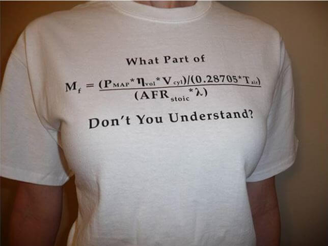
We’ve all seen the famous Greg Banish, Calibrated Success T-shirt which you can buy from Summit Racing, and I’m wearing mine now actually. I’m not sure I understand whether Mr Banish was expressing frustrating saying that it’s simple, why don’t people understand it – or if he’s making a joke and saying that actually there are many different terms in this equation, and if you don’t understand them all then you can get lost quickly. But either way, if it looks intimidating to you now, you’ll understand it in about twenty minutes so don’t worry.
Let’s talk firstly about the way that we and other ECU manufacturers used to do things, and hopefully you’ll see why we’ve changed to a proper fuel model now. Firstly, what is the purpose of the injector control in the ECU? It’s to get the right amount of fuel into the engine, to achieve a particular lambda…. when the tuner isn’t there to correct it! That means that we’re trying to control the injectors and deal with all the different conditions that will occur that will affect the lambda, if we don’t care about them.
The fuel requirement of an engine varies mostly with manifold pressure, and to a lesser extent it varies with RPM. The obvious way is therefore to have a table of millisecond values as a function of both MAP and RPM, and we’d call this a fuel map. And this works quite well, so long as all the other variables are constant.
So which variables are not included in this calculation, and we’re assuming are constant, but actually are not constant? When I did this at PRI I let people call them out and I threw Tim Tams to people who answered, but I can’t do this here so I’ll just tell you the list I came up with:
- Temperatures – coolant, air, fuel
- Fuel pressure
- Battery voltage
- Fuel composition (ethanol vs petrol)
- Injector type
Now, I realise that the Injector Type isn’t really a variable, because it’s supposed to be something that’s installed on the car before you do a tune. And there is some case to say that it would be nice to be able to change injectors and not have to do a complete return. But that’s not the main point. The main point is that often tuners tend to specialise in particular engine types, and end up developing a decent library of maps for these engines in which they specialise. However often they don’t get to choose the injectors on the engine when they have to tune it, so they don’t get to use one of their maps from their library because the milliseconds are all wrong.
So to deal with these variables, what ECU manufacturers (including us) used to do is to add in “compensation tables” for all of these variables. For example to deal with battery voltage changes, old ECUs had a “battery voltage compensation table” where you could enter a number of milliseconds to add to the injector duration as a function of battery voltage.
Now, as a tuner, how do you know how to set this table? How many tuners are going to run the EFI system off a variable power supply and wind it up and down, adjusting the table so that the AFR at idle is constant? I don’t know many tuners who would do that.
Similarly for temperature changes, you have separate tables for coolant temperature and air temperature, which makes life very complicated. How do you know if it’s the air or the coolant table which is wrong, for example? In general the more correction tables that you have, the harder it is to know which table needs to be adjusted, and the longer it takes. And to be honest, if you have all these compensation tables to account for incorrect assumptions you’ve made about other variables being constant, maybe your model isn’t that good in the first place. As in, maybe having a millisecond map against RPM and MAP isn’t the right way to do it.
So let’s go back to chemistry and physics and work it out from first principles instead of making these assumptions.
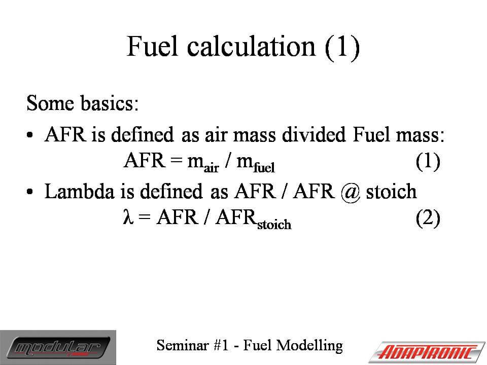
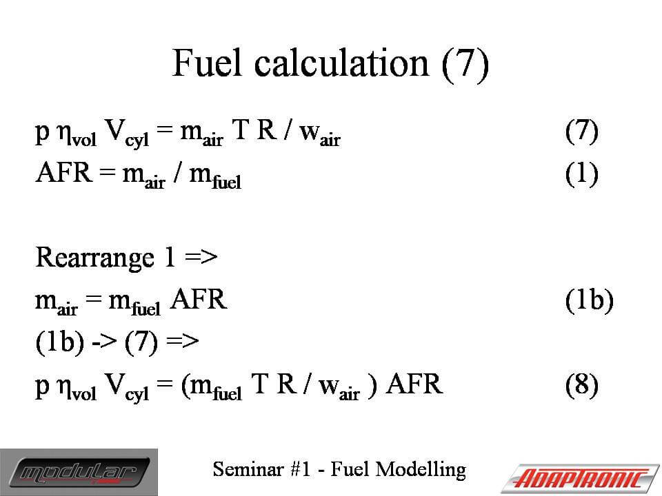
This is just the definition of an Air-Fuel ratio, and the definition of Lambda.
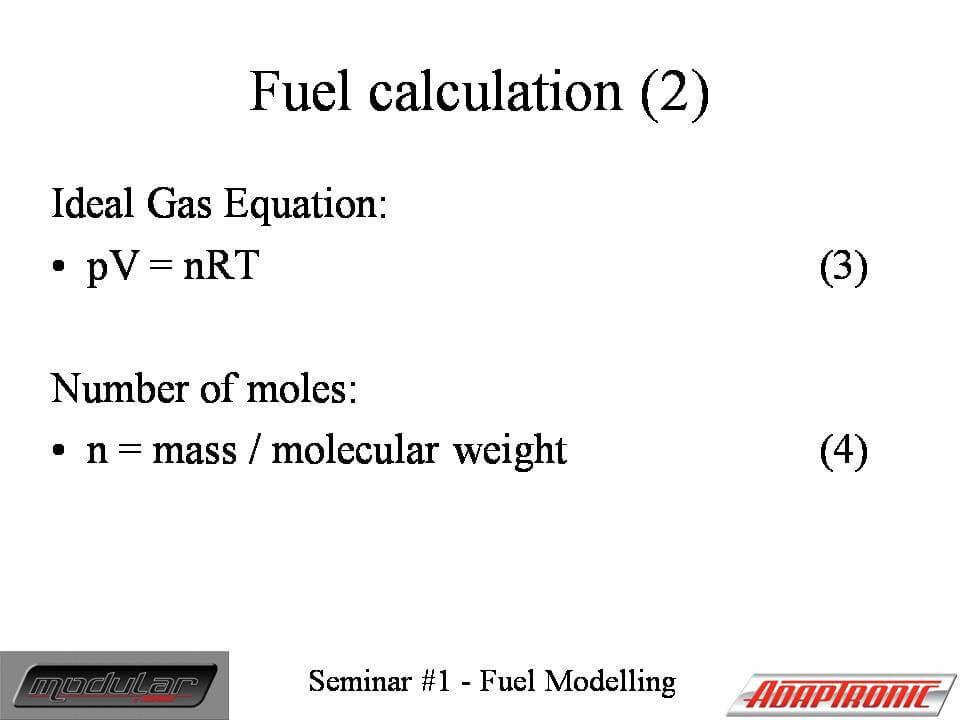
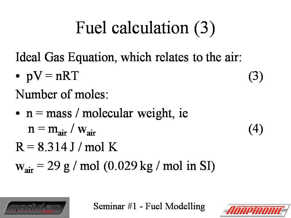
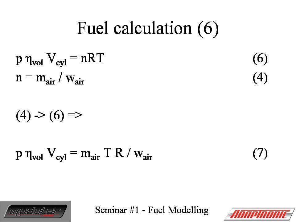
The top one is called the Ideal Gas Equation or Boyle’s Law, and it’s given by the pressure times the volume equals the number of moles times the ideal gas constant times the temperature. Note that the pressure and temperature in this equation are absolute temperature and pressure.
The second one is the conversion between number of moles into mass, based on the molecular weight of the gas. A mole is defined as approximately 6.022 x 10^23 molecules in this case. We don’t count the molecules, we just work it out from the weight and knowing what air is made of.
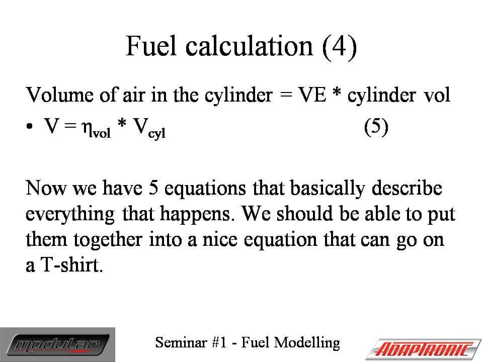
This is the definition of volumetric efficiency. It’s given by that Greek letter Neta, which looks like n, which is the thermodynamic symbol for efficiency, and it’s given by the ratio of the effective volume of air that travels through the inlet valve into the cylinder, if it was the same pressure as in the manifold, divided by the swept volume of the cylinder. In practice of course the volume expands or compresses to fit in the cylinder anyway, so it’s the pressure that changes, not the volume, but volumetric efficiency is a way to think of it.

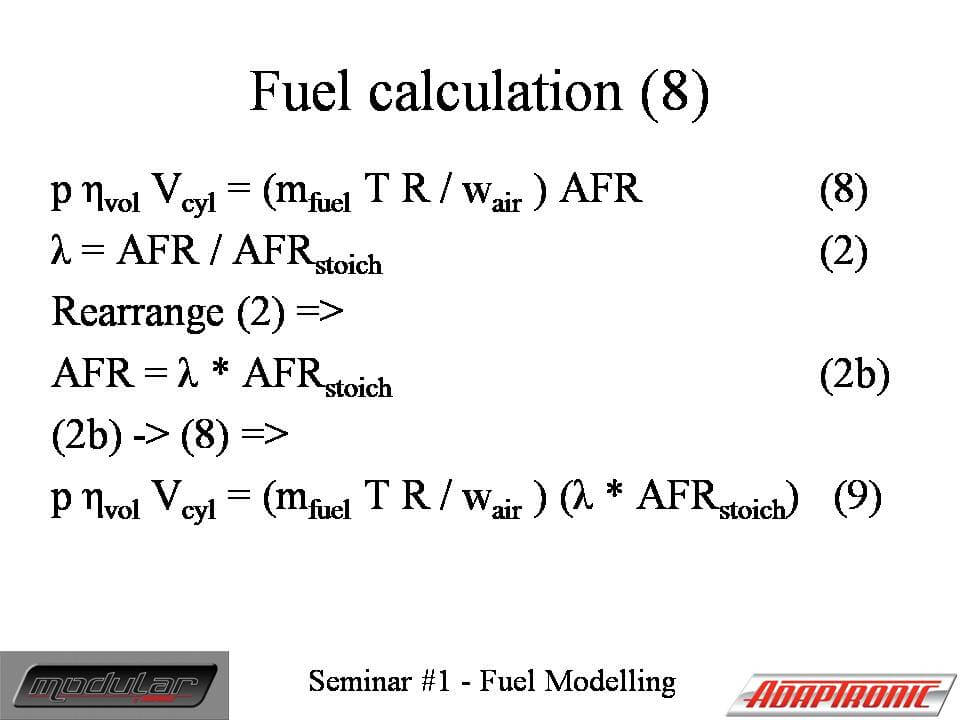
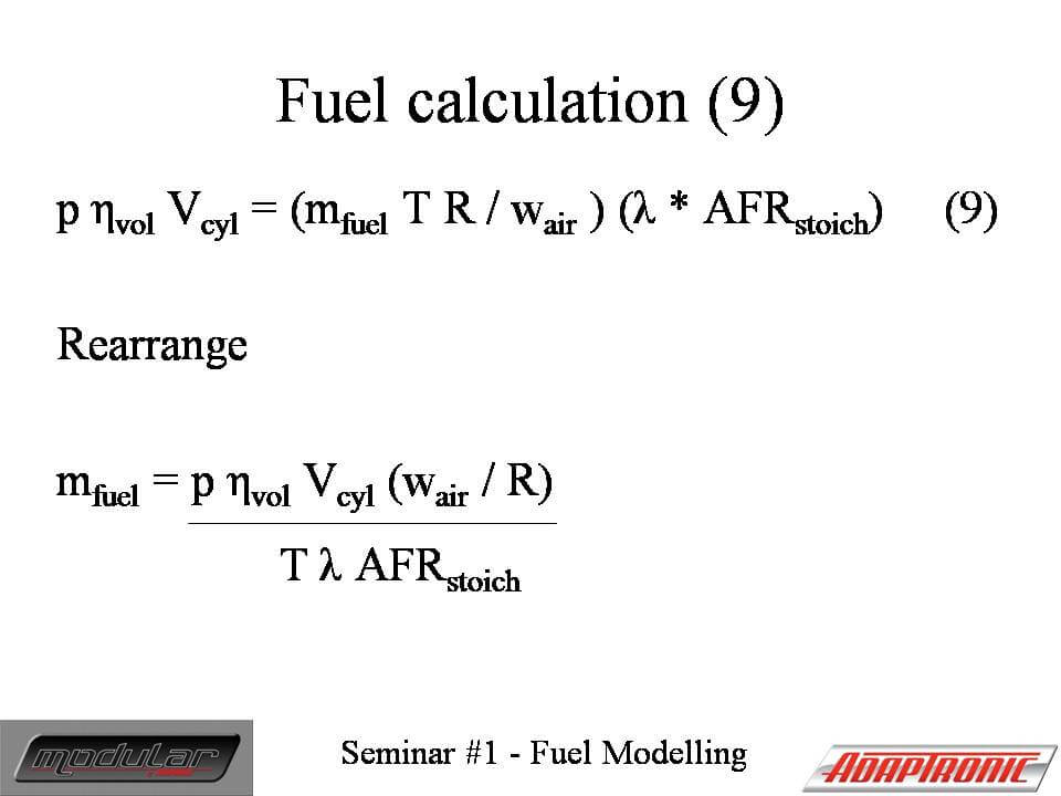
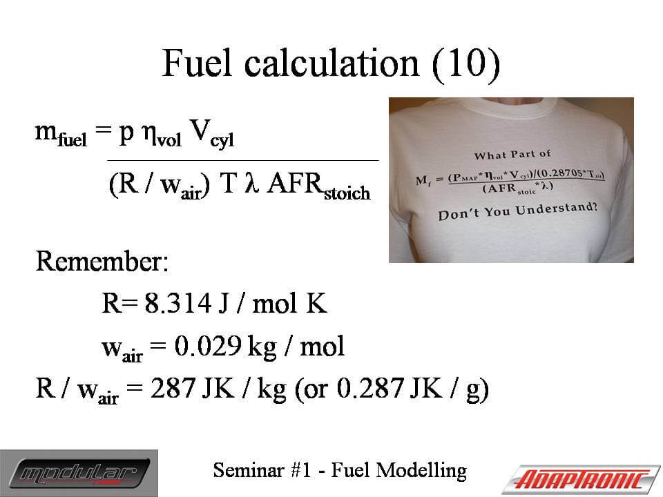
You can see now that we’ve essentially arrived at Greg’s T-shirt equation. There’s a scaling difference of 1000 in there, so I assume that’s because he’s calculating fuel in grams instead of the SI unit of kg or something like that.
Now, let’s go over all the variables again and see how we can measure or know what they are.
Mfuel is what we’re trying to calculate
MAP is something that we can measure directly with a MAP sensor. To learn more about how you can measure this accurately, see the video on configuring inputs because there are some funky requirements regarding filtering, because the MAP is not constant throughout a cycle.
VE is something we can look up from the fuel map. This replaces our millisecond fuel map. Please see my tuning modes video for a more detailed discussion of VE, what affects it on different types of induction systems.
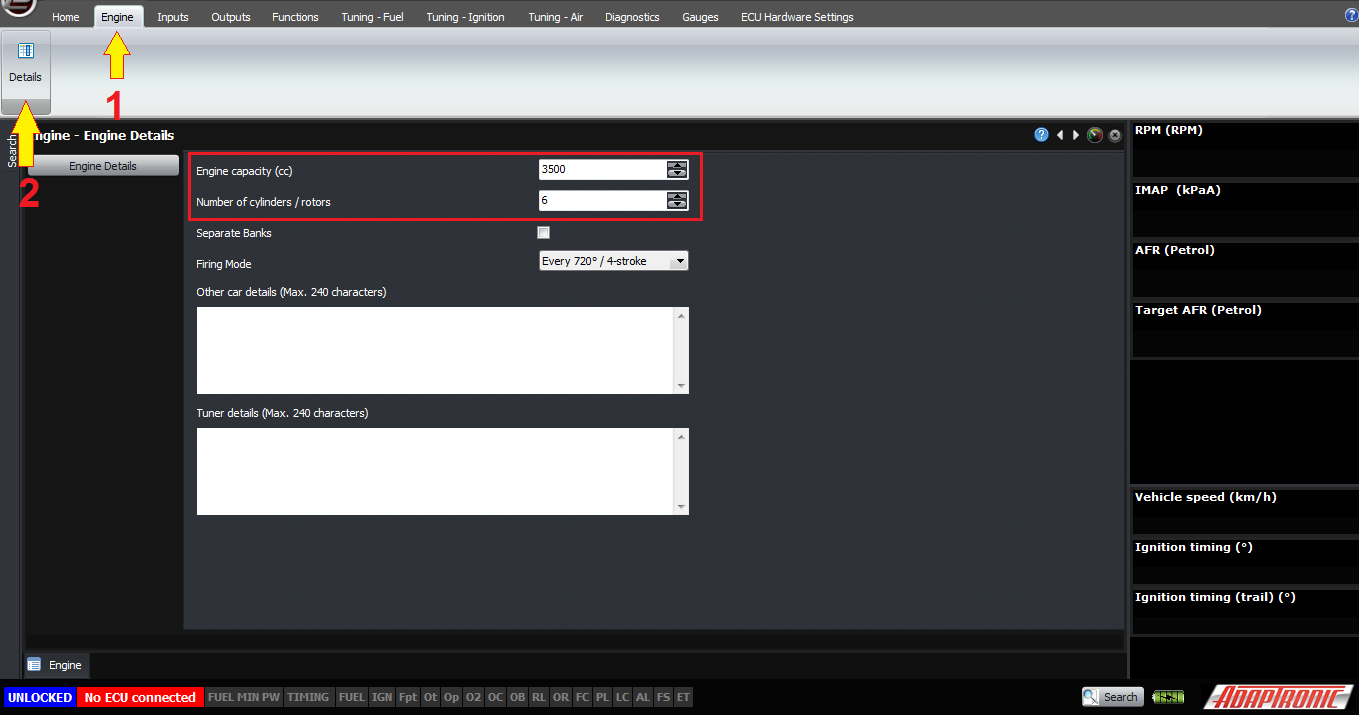
Vcyl – cylinder volume, the ECU knows this at setup time because of the engine capacity and number of cylinders.
T – the air temperature, is taken as a blend between air and coolant temperature; I’ll do a separate article just on that topic.
Lambda, is the lambda that we want, so that just comes from the target lambda table
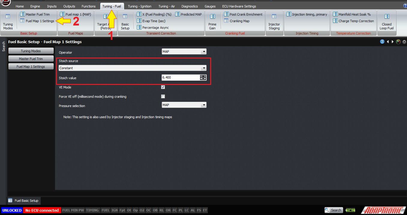
AFRstoich comes either from an ECU setting, or is calculated from measurement from a flex fuel sensor.

There should be some implications of this formula. For example if you double the manifold air pressure, then all other things being equal, the amount of fuel you need to inject every intake stroke will approximately double. Sometimes people ask questions like “why does the VE map look so flat, why doesn’t it increase a lot with boost”, but it should be obvious when you see this formula.
Another question we get asked is, if I change the target lambda, will the ECU change the amount of fuel injected. And again, you can see from this formula that the answer is yes.
This formula also means that in theory, your temperature correction maps should be zero, because they are supposed to be handled by the formula. And in practice, I have always left them at zero so far, and it works well because the model is accurate.
Let’s look now at how this is all set up in the ECU. There are separate videos / articles on each of these topics so I’ll just tell you where all the settings are here.
Engine capacity and number of cylinders (or rotors) are both set up in Engine -> Details.
The stoich AFR is set up in the fuel map settings, for example Tuning – Fuel -> Basic Setup –Fuel Map 1 Settings. This location also allows you to set how the VE fuel map is configured, and also where the VE mode setting is located.
There’s another article specifically about tuning modes, how to set up the load axis for fuel maps based on the type of induction system on the engine.

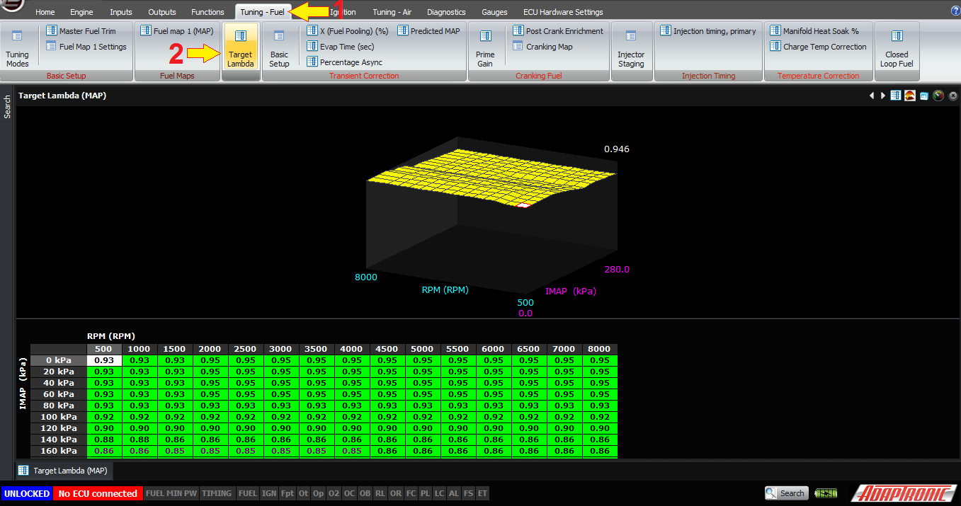
Target lambda can be found in Tuning-Fuel -> Target Lambda
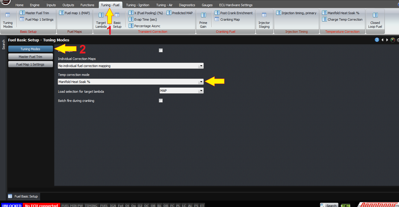
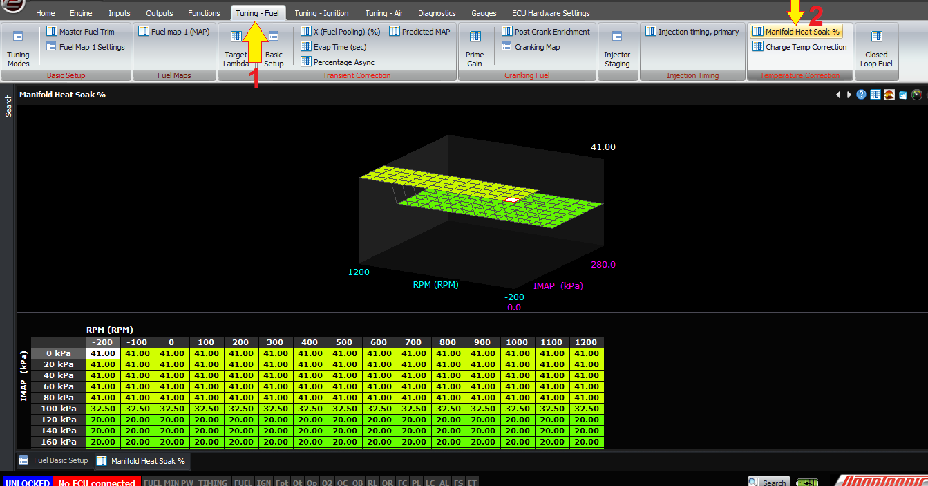
The temperature is taken from the coolant and air temperature sensors. By default, we use the manifold heat soak % mode which uses a blend of the two. This is enabled in the Tuning-Fuel -> Basic Setup -> Tuning Modes page, and the heat soak percentages can then be found in the Tuning-Fuel -> Temperature Correction -> Manifold Heat Soak %. This is the amount of weight to give to the coolant temperature, eg 100% means that there’s so much heat soak that by the time the air gets into the engine, its at engine temperature and the original air temperature doesn’t matter at all. 0% heat soaks means that there’s no effect on the air temperature by the engine temperature at all, which never happens in practice.
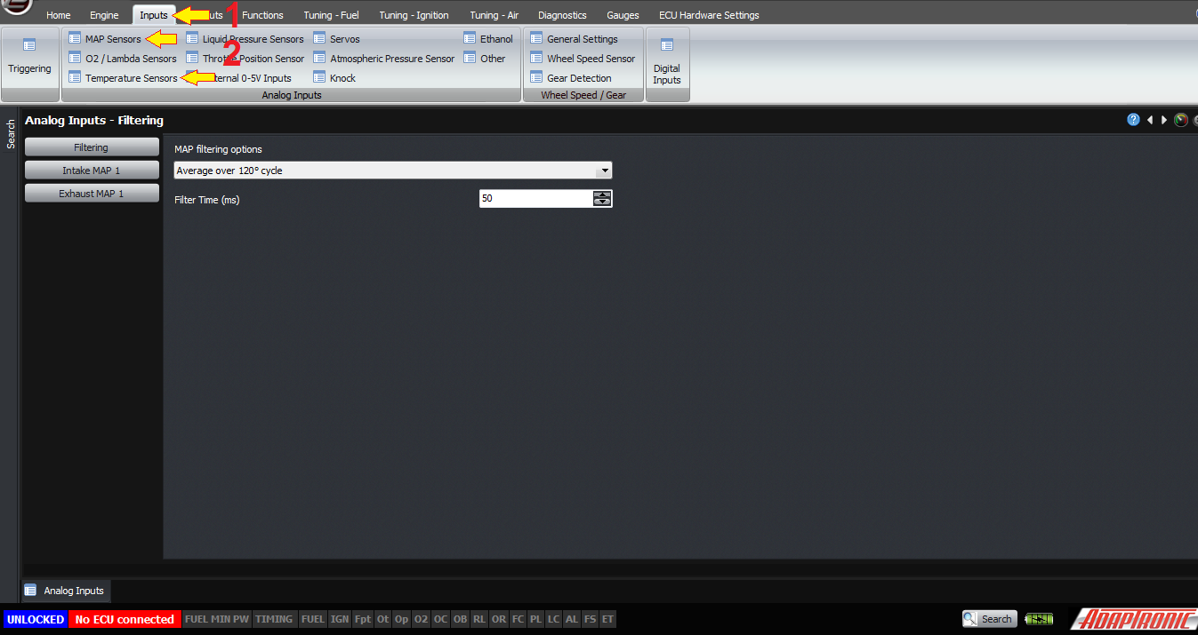
MAP and temperature inputs are configured in the Inputs menu, and there’s other article that talks about those specifically.
This doesn’t get you all the way to the injector millisecond value though, it gets you to the fuel mass. There’s a separate article on this, which includes the injector model, minimum pulsewidth or fuel delivery, the effects of fuel pressure and fuel temperature and so on. This also does not discuss transient conditions which is done in another article.
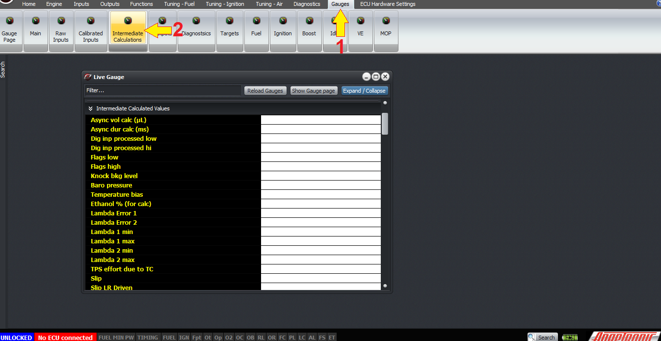
Finally, the ECU reports a lot of its intermediate calculated values. So you can see things like the actual VE read from the table, and the calculated stoichiometric AFR, the calculated charge temperature and so on by going to the gauges window and expanding the “intermediate calculated value” section.
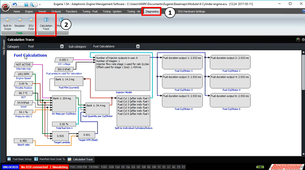
You can also see this diagrammatically by going to the Diagnostics -> Calculation Trace. The main fuel display shows the whole fuel calculation which is quite large, but you can click on individual sections in it to go into more details of the calculation. This also works with the software simulator.
Thank you!
©2018 Adaptronic