Different Fuel Tuning Modes on Modular ECUs

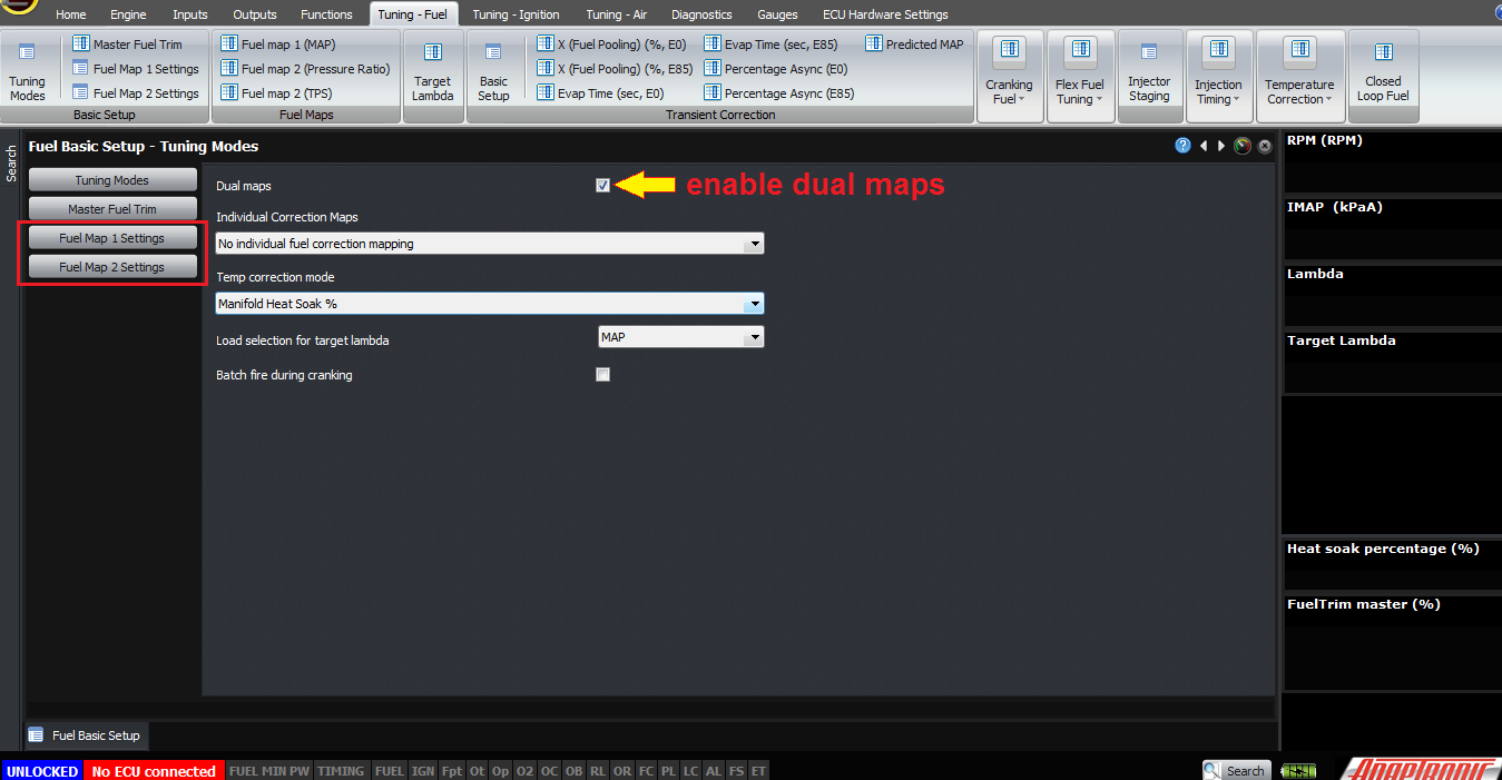
There are many different ways that ECUs can calculate the fuel requirement of an engine. On the Modular ECUs this is part of the fuel map setting, so in a dual map mode, you have the option for different calculation methods between fuel maps 1 and 2. We will describe this as though you’re only changing it for fuel map 1, but it applies equally for fuel map2.
The Modular ECUs operate on the volumetric efficiency tuning principle. For those not familiar with this, I did a talk about this at PRI in 2016, but I will be doing another video in this style to explain it with specific reference to the Modular ECU.
So the whole purpose of the tuning mode selection is to tell the ECU how to work out the volumetric efficiency.
There are currently 4 modes supported, and these are selected by the “operator” selection in the fuel map settings. They are:
- MAP
- TPS
- MAP x TPS
- MAP + TPS
Let’s take a step back and look at what affects the volumetric efficiency of an engine. Firstly, we all know that RPM affects volumetric efficiency, because otherwise the torque curve would be a flat line, so that must be one variable of the fuel map. The other variable that affects the volumetric efficiency is the pressure ratio across the engine. Why is this?
For the sake of simplicity we’ll just talk about 4 stroke piston engines because they are easiest to visualise. The same principles apply to 2 stroke piston engines and rotaries though. We’re all familiar with the 4-stroke cycle, induction, compression, expansion (or power, combustion) and exhaust. At the end of the exhaust stroke, the clearance volume at the top of the chamber is filled with exhaust gas, and the gas is actually at the exhaust manifold pressure. On a naturally aspirated engine with a free flowing exhaust, you can consider this to be atmospheric pressure. On a turbocharged engine, this pressure will be higher than atmospheric pressure so that there is a pressure drop across the turbine to make it spin.
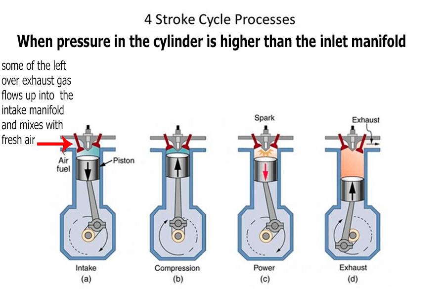
When the inlet valve opens, what happens next depends on the pressure ratio across the inlet valve. If the pressure in the cylinder is higher than in the inlet manifold, some of the left over exhaust gas flows up into the intake manifold and mixes with the fresh air coming in. The result then is that the air that’s actually sucked into the engine (or pushed in by the atmospheric air pressure) is diluted with exhaust gas, and that has the effect of reducing the volumetric efficiency. If they are at approximately the same pressure, for example on a naturally aspirated engine at wide open throttle, then very little gas transfer occurs and the cylinder sucks in approximately its swept volume in fresh air, with an amount of left over exhaust gas from the previous cycle consistent with the clearance volume. In the other case, if the inlet pressure is higher than the exhaust pressure, for example a supercharged engine at wide open throttle, you can open both the inlet and exhaust valves at the same time and the higher inlet pressure can blow the remaining exhaust gas out the exhaust port. This procedure is called “blowing down”, and has the effect of increasing the volumetric efficiency, possibly to a value higher than 100%.
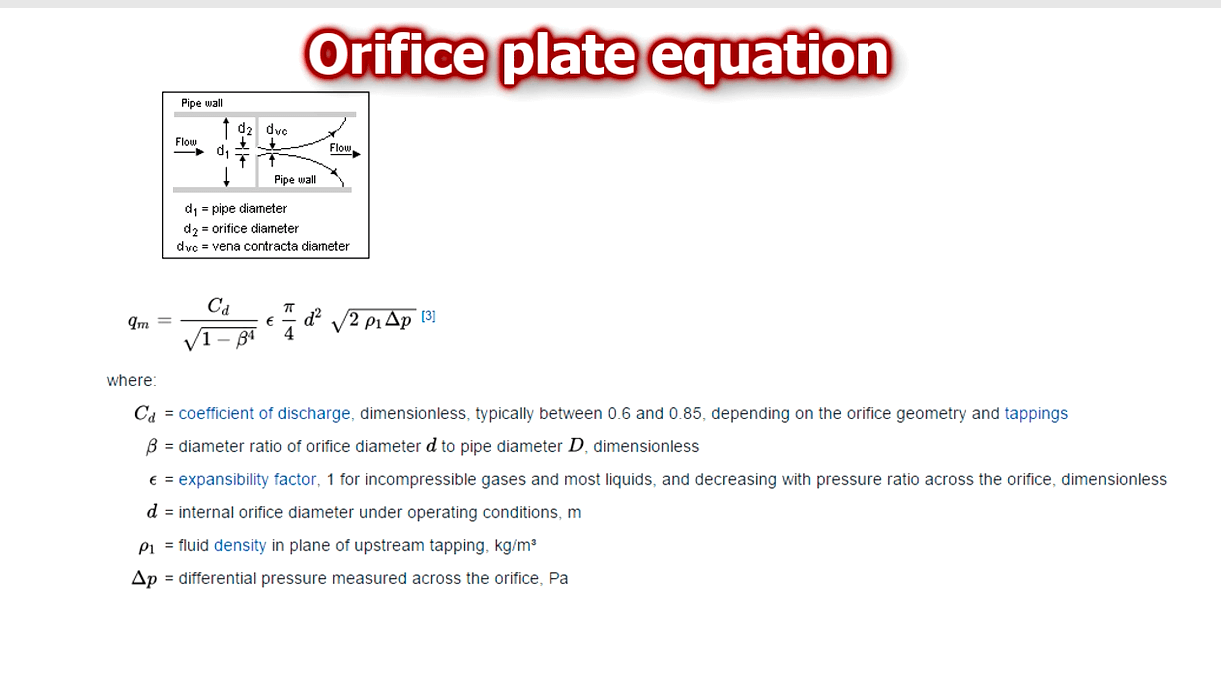
The reason that it’s the pressure ratio across the inlet port that makes the difference rather than a pressure difference is that if you research the orifice plate equation, you’ll find that the equations work out to give a pressure ratio, rather than a pressure drop. This makes sense intuitively, for example if you have a pressure drop of 2 PSI across an intercooler at 15 PSI boost, it would be pretty naïve to think that you’d have the same drop of 2 PSI when you try to force 30 PSI through it.
So this means that the volumetric efficiency is mostly dependent on the pressure ratio, which means IMAP / EMAP, intake manifold absolute pressure divided by exhaust manifold absolute pressure. This can be achieved, or approximated, in a few different ways:
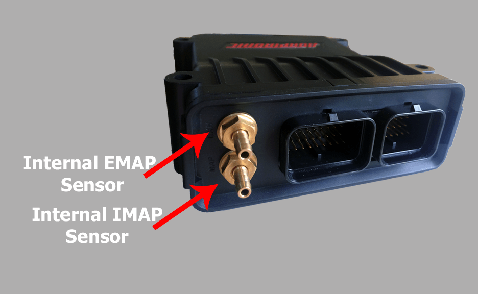
- Direct measurement. This requires an inlet and exhaust manifold pressure sensors. I describe how to configure these in the inputs and sensor configuration video, including some considerations for EMAP sensors, so I won’t repeat them here. This is the best method, and automagically compensates for barometric pressure changes, different turbochargers, exhaust restrictions and so on. For example on a conventional MAP tuned car, if you change to a less restrictive intercooler, then at the same MAP, the turbocharger needs to generate less boost because there’s less pressure drop. Therefore it requires less exhaust back pressure (EMAP), because it needs to make less boost. Therefore the engine will “breathe” better and make more power at the same boost level, and if the car was tuned on MAP then you would need to retune it. If the car was tuned by IMAP / EMAP, no change to the tune is required.
- Assume that EMAP is the barometric pressure. This is fine if you know your exhaust is not very restrictive, which means you can’t have a turbocharged engine.
- Just tune based on MAP. This has the limitation I mentioned above.
- Some tuners like to use MGP instead of MAP,
claiming that it compensates for barometric pressure
automagically. The method the reflects the physics is IMAP
/ EMAP, so the question is really how accurately does IMAP
– EMAP (which is MGP) approximate IMAP / EMAP? Well, at
WOT it’s 100% accurate. At high vacuum it’s very
inaccurate, and MAP is a much better estimate. On boost,
MGP is more accurate than MAP.In this following graph, the
grey line (pressure ratio) shows what the engine is
actually doing. The blue line is the position in the fuel
map that the ECU would look at if you used MAP as your
load lookup, and orange is what the ECU would look at if
it used MGP as the load lookup.
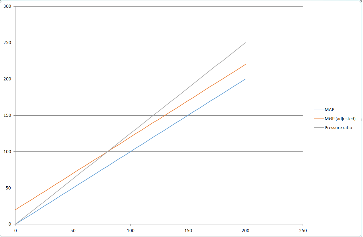 This
example is with 80 kPa barometric pressure instead of 100.
You can see that above about 40 kPa, MGP is closer to the
line than MAP. At vacuum, MAP is closer.
This
example is with 80 kPa barometric pressure instead of 100.
You can see that above about 40 kPa, MGP is closer to the
line than MAP. At vacuum, MAP is closer.
You also need to remember that the VE map of an engine is not flat at a constant RPM.
You can see from this map that the VE changes a lot more at high vacuum conditions than close to atmospheric and above. For example in this map, whether the ECU sees the 100 kPa site or the 125 kPa site makes no difference to the VE. Remember that the load axis is separate from the MAP factor in the VE equation anyway, so it’s only the difference in VE that we’re looking at.
Engines with individual throttle bodies present a different challenge because the air does not settle fully between the throttle bodies and the engine. You can measure the pressure at the port, and you can even (and you should) take multiple ports and join them together to get a more accurate reading. However at part throttle, and especially at higher engine speeds, the pressure that you measure at the ports will over-estimate the amount of air the engine is ingesting. So effectively, the engine’s volumetric efficiency changes with throttle position.
I have also met tuners who have said that on a single throttle engine with a large plenum, and the engine has a large overlap duration and produces little vacuum at idle, they can not get a good tune on pressure or pressure ratio alone, and they need to be tuned on throttle position. I haven’t witnessed this myself and I’ve set up and tuned plenty of engines that make very little vacuum at idle, but again I’m open to more information about this and we offer TPS tuning if that’s what you want to do as a tuner.
Now that we have an understanding of what engines actually want, we can look at the different modes, selected by the “Operator” setting.
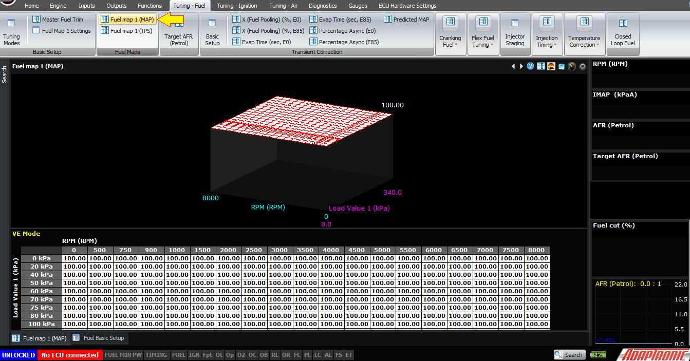
The first one, and the most basic, is MAP only. This is the one that the majority of people will use, and it’s what you’d use on a standard engine with a single throttle and a plenum. In this mode, you have one fuel map, which has RPM on one axis and pressure on the other.
The pressure axis is selected in the “pressure selection” setting. This can be either IMAP, or IMAP / EMAP or MGP. These affect the scaling of the load axis of the pressure map. The pressure map can be up to 31 x 31 and the points can be arbitrarily spaced and changed in real time as the engine is running.
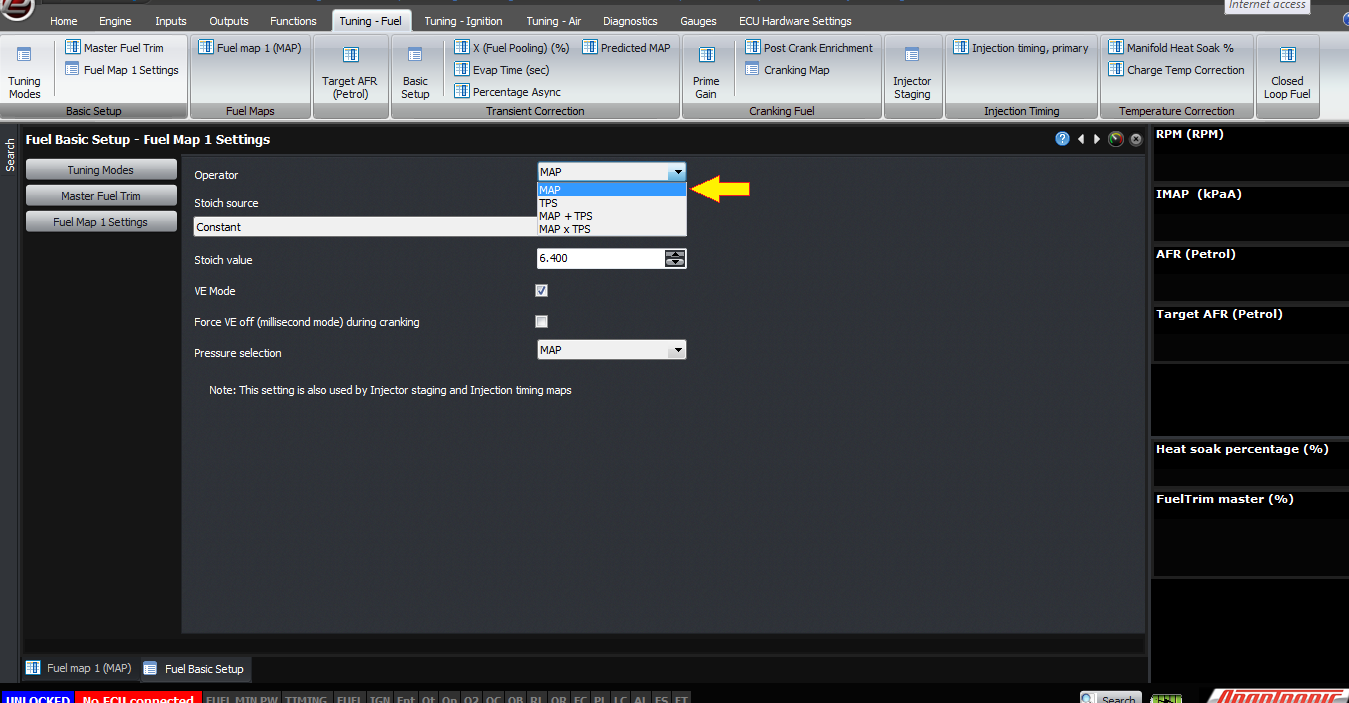
(1) Select operator
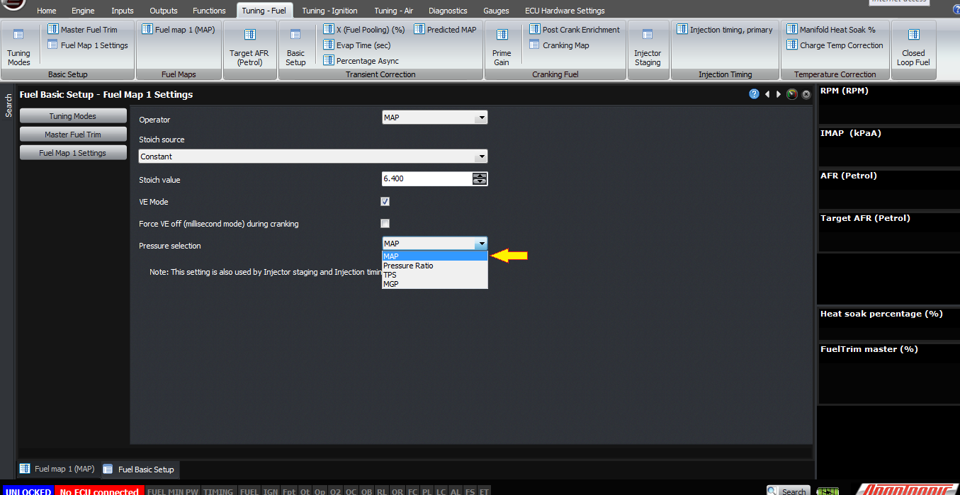
(2) Choose preferred “pressure selection”
If you have a naturally aspirated engine which either has individual throttles, or an inlet without a decent plenum, then you might want to use TPS instead of MAP. So when you select TPS instead of MAP, the pressure map disappears and instead you have TPS map against RPM. This can be a maximum size of 15 x 31 data points and they can be all arbitrarily spaced. Since it’s a VE map, the actual MAP will still be used as part of the fuel calculation, as will temperature, stoich ratio and target lambda.
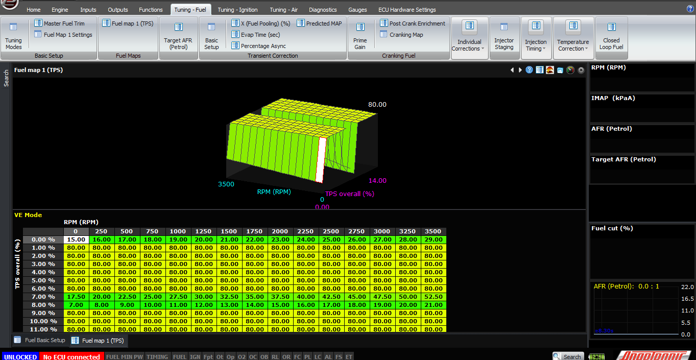
Operator is set to TPS. Fuel map has TPS against RPM
If you have an engine like the above, but it has forced induction, then we recommend using MAP x TPS mode. This is what you would use on an RB26DETT GTR engine for example, or a turbocharged semi peripheral 13B with staged throttles.
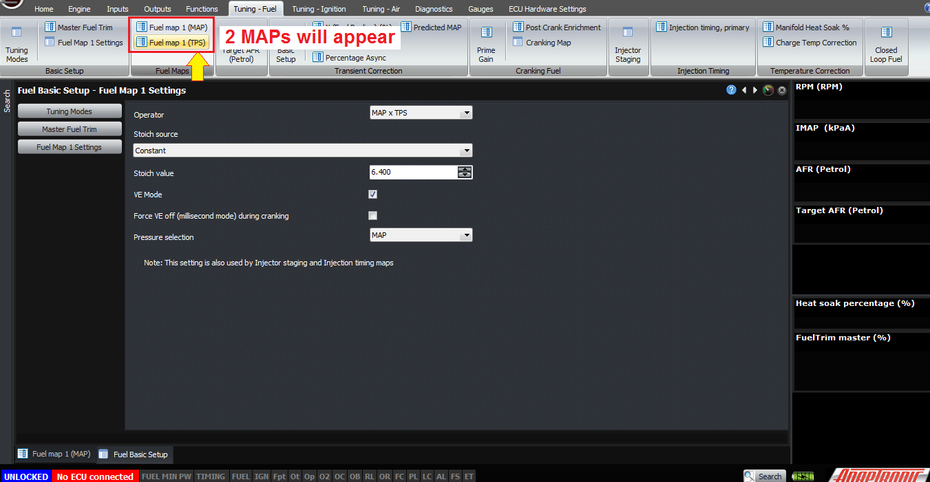
In this mode, the way we generally recommend to tune is to use the pressure selection to be MAP, and set the entire pressure map to be 100. Then do the tune on the TPS map up to wastegate boost pressure – after that you can wind up the boost and make any corrections on the pressure map. The calculation is very simple, it’s just a multiplication of the two maps. For example you are at 2000 RPM, 20% throttle and 90 kPa MAP, then the ECU will look up the 2000 RPM, 20% TPS point, which might be say 60% – and the 2000 RPM, 90 kPa point in the pressure map which might be say 90%, and then the overall VE calculated is 60% x 90% which is 54%.
There is a final mode called MAP + TPS, which is the same as MAP x TPS but the two numbers are added instead of multiplied. I don’t know a circumstance where that would be useful but we’ve had a few requests for it so it’s been included.
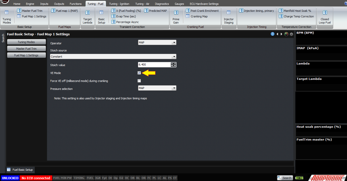
For all of these, the VE mode should be selected. If you do not select VE mode, then the maps become millisecond maps instead of VE maps. The injector model will not be followed, you will need to do all the temperature correction the old fashioned way and we highly recommend against not using VE mode because basically you’ll be re-implementing every already built into the ECU.
Just a few miscellaneous points now.
Firstly, the stoichiometric ratio has to be set for the fuel that you’re running. The dual fuel maps mean that you can run a separate fuel in each map and therefore have a different stoich ratio for each. There will be a separate article for setting up flex fuel mode.
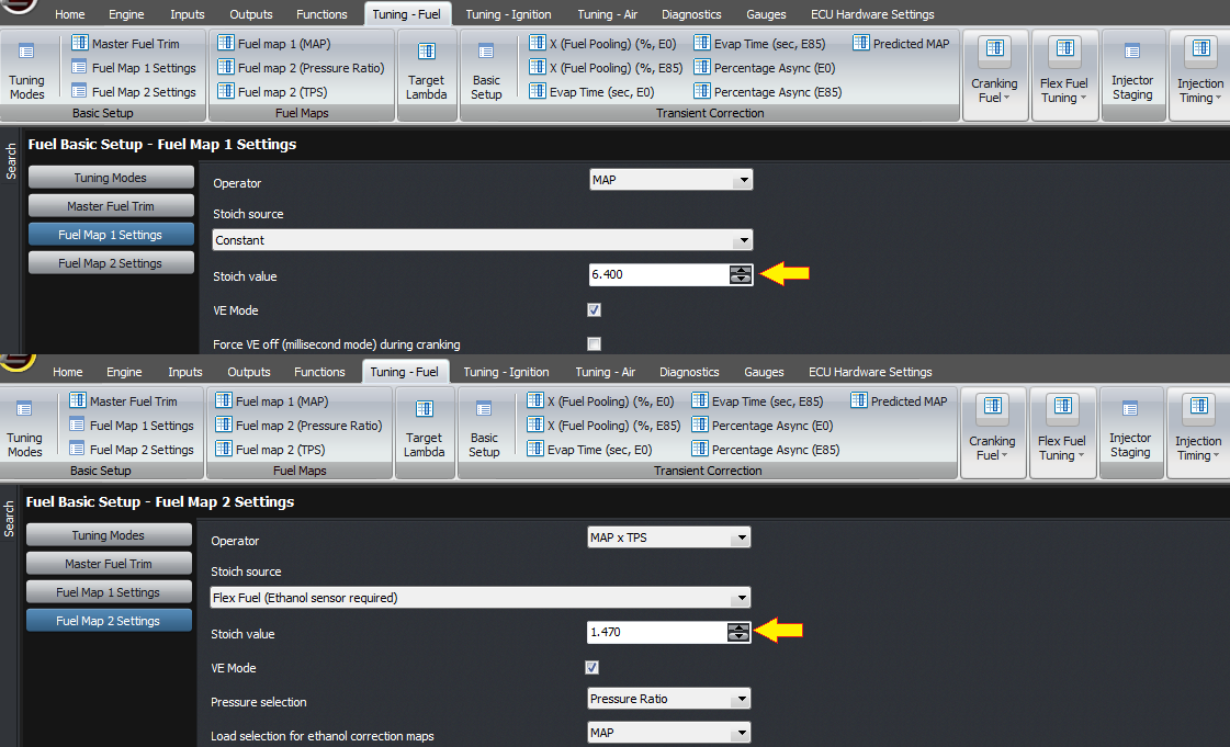
stoich value for each map can be changed
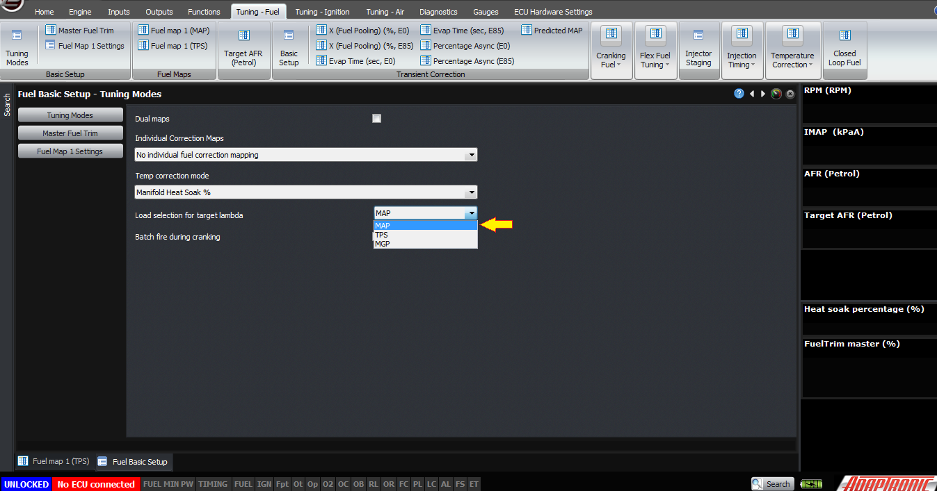
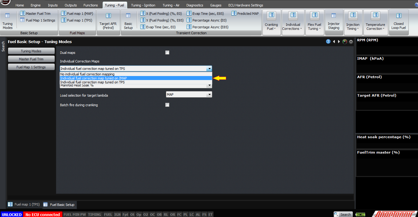
Secondly, under the global tuning modes, you can select the axis for target lambda, being TPS or IMAP, and also you can enable the individual fuel correction maps. If you enable the individual maps, then you can select the axis for them as being either IMAP or TPS, and then you can map the individual fuel corrections for each cylinder or rotor.
Thank you and happy learning!
©2018 Adaptronic