How Fuel Mass is Converted to Milliseconds on Modular ECUs

If you’ve see the other videos or articles about how the ECU calculates the amount of fuel to be delivered, you’ll have seen that the end result of those is in the units of fuel mass, not milliseconds. This article explains how the ECU converts from fuel mass into milliseconds, and a bit about how injectors behave.
Firstly, let’s talk about injectors. A fuel injector for low pressure EFI, as used on every port injected engine, is an electromechanical device. It has mechanical and electrical properties which are often not that well understood.
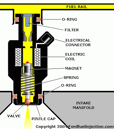
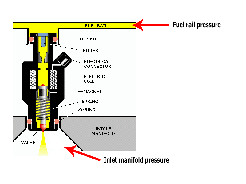
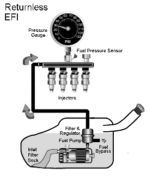
In this description I’m going to talk about fuel pressure. When I talk about fuel pressure, I’m talking about the differential fuel pressure across the injector, ie the fuel gauge pressure minus the manifold gauge pressure. If you have a manifold referenced regulator, this should be pretty much constant.
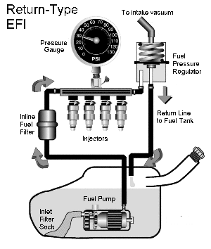
Manifold Referenced Regulator
The fuel injector is designed so that the fuel pressure holds the injector closed. The injector contains an electromagnet, or solenoid, which pulls the injector open against this fuel pressure force. The force which the solenoid exerts is proportional to the current flowing through it, and therefore you need a certain current to overcome the fuel pressure and cause the injector to open.
Electrically, the solenoid has inductance and resistance. So its response can be written using the differential equation:
v = L di/dt + iR
where:
- L is the inductance
- R is the resistance
- i is the instantaneous current
- v is the instantaneous voltage
If you’re not familiar with differential equations, you might be able to see or guess that the injector current depends on the voltage that’s applied to it. A higher voltage gives you a higher injector current. Not only that but the higher voltage also causes the current in the injector to build up faster. Therefore the amount of time it takes for the injector to open depends on the voltage applied to it.
Furthermore, at higher fuel pressures, higher injector current is required for the injector to open. Therefore the amount of time it takes for the injector to open depends on both fuel pressure and supply voltage.
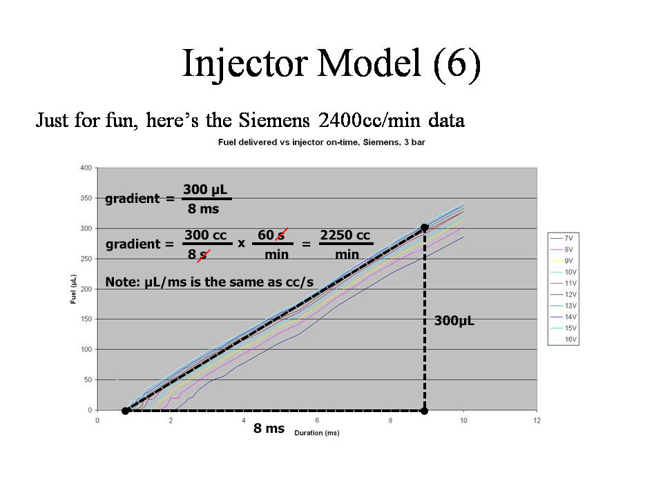
Below is an example response from an aftermarket injector, the Siemens 220lb/hr, taken at 3 bar of fuel pressure.
This graph should be a straight line, intercepting the X-axis at the amount of time it takes for the injector to open, and then going up from there at a slope determined by the injector flow rate.
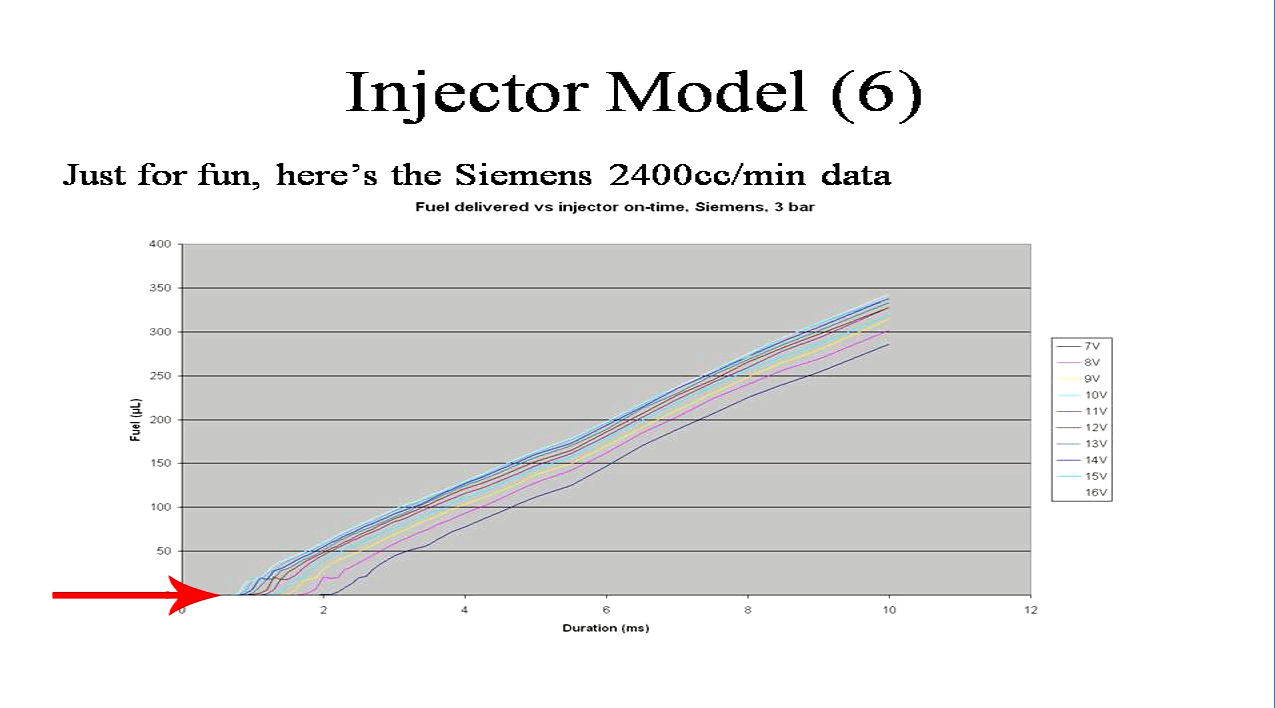
X-intercept is the line pointed by the arrow
In practice we see several lines. These correspond to different supply voltages for the injector. You can see that the higher voltages cause the injector to open more quickly, but once the injector is open, the fuel flow rate is basically independent of voltage.
If you have sharp eyes you will also see that at low opening times, that is if we’re trying to deliver 25µL of fuel or less, the curve has a bit of a kink to it. This is because of pintle bounce – you only see this on underdamped injectors; many don’t exhibit this behaviour at all. But what it means is that if you want to deliver less than 25µL of fuel, it’s going to be hard to achieve that accurately with this particular injector.
For every injector at any given pressure, there is a minimum voltage required to open. We find in testing some injectors that many of them won’t open at say 5 bar fuel pressure at a low voltage like 7 or 8 Volts. In some cases injectors don’t open reliably with 4 bar at 9V. You might be asking the question “who cares; I have a decent charging system on my car” but your charging system isn’t working when you’re cranking the engine. It’s very common to see the supply voltage drop to 8 or 9 volts during cranking, and if you’ve upgraded your injectors to larger ones, but they aren’t high powered enough to open at the low voltage at your nominate fuel pressure, you’re going to be wondering why your engine won’t start. People sometimes misdiagnose this – because after you let go of the starter the voltage recovers quickly as the engine is still spinning down, so the ECU is still injecting fuel pulses during this time. Then when they hit the key the second time, it starts. Because they haven’t diagnosed the problem correctly they say that their problem is it always takes 2 attempts to start, rather than my injectors aren’t opening during cranking. Both are correct but the first one would have you chasing cranking fuel settings when that’s not the problem.
Fuel injectors are essentially volume delivery devices, because their flow rate does not change very much with temperature. Therefore in this translation from mass to milliseconds, we need to first calculate the volume.
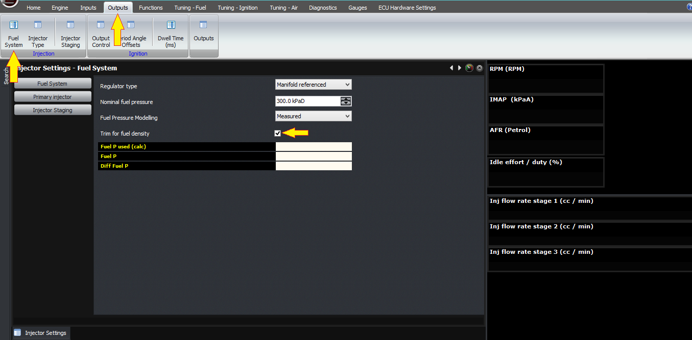
The ECU calculates the density of the fuel based on the stoichiometric ratio, and the temperature if enabled. The stoich ratio can be a constant, or it can be measured from a flex sensor, but either way the ECU calculates the basic density from this.
If under the fuel system settings you enable “trim for fuel density”, then the ECU will also compensate for changes to the fuel density due to temperature (which themselves differ between E0 and E100). This requires a fuel temperature sensor, which can either be wired in, or you can read the fuel temperature from a flex fuel / ethanol sensor.
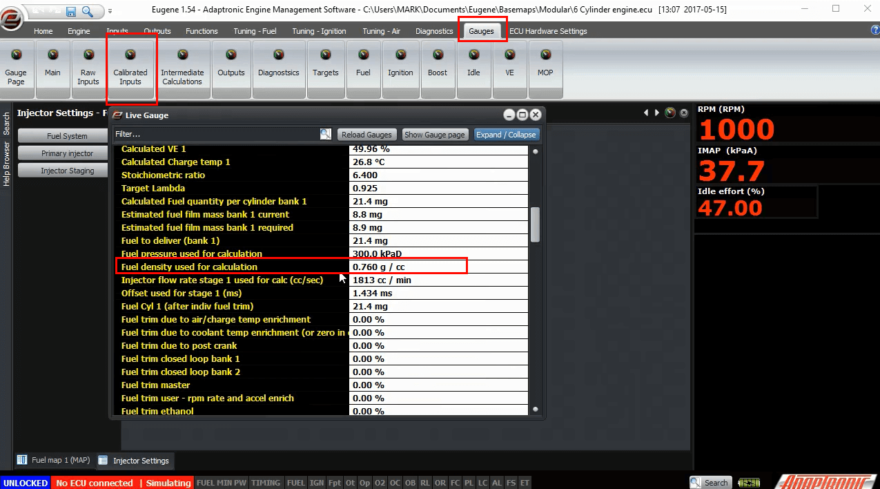
The current estimate of the fuel density is one of the variables that you can see in the gauge window under Intermediate Calculated Variables.
From the mass and the density, the ECU now knows the fuel volume to deliver. This volume is split between the different stages in accordance with the algorithm I described in the injector staging video. Then each volume for each injector is converted into a millisecond duration. This is done as follows.
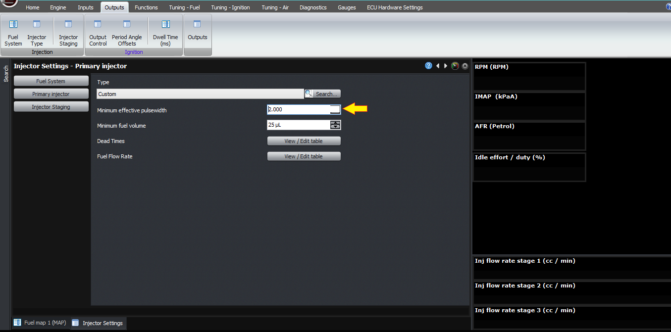
Firstly, you can specify a minimum fuel volume for the injector to deliver. If you enter a non-zero value in this setting, the ECU will “clip” the value using this as a minimum. For example if you look at the injector performance graph and find that the injector is unreliable at less than 10 µL, you can enter 10µL and instead of the ECU trying to deliver 8 which might result in missing fuel all together, it will deliver 10.

Secondly, the ECU then calculates the effective on-time from knowing the flow rate and the volume required to be delivered.
For those who prefer to think in effective milliseconds rather than fuel volume, the Modular ECUs also have a minimum effective on-time which can clip the fuel duration, so you can use either this one or the volume based one. Just set the other one to zero so they both aren’t working together!
Next, the ECU has a 3D map of offset, or dead-time, as a function of battery voltage and fuel pressure. Note that this is the differential fuel pressure, so the pressure across the injector. This can be determined in 2 ways.

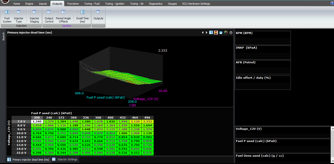
The first way is to measure it directly using a fuel pressure sensor. See the sensor setup video for information on how to configure pressure sensors. The ECU then measures the fuel pressure and subtracts the manifold pressure to determine the differential fuel pressure, which is a variable you can see on the gauges window and should be fairly much constant with a manifold-referenced regulator. The ECU then uses this value to look up the offset and flow rate the injector settings.
The second way is to use a nominal figure that you enter. For this, there are two types of fuel systems that we support; one is the manifold-referenced pressure regulator, where the pressure regulator aims to achieve a constant differential fuel pressure. The other is the fixed pressure, where this is no hose from the inlet manifold to the pressure regulator, and the gauge fuel pressure is constant. In this mode, the differential fuel pressure varies based on manifold pressure, so the ECU needs to know this to know to look up different flow rates and offsets as the differential fuel pressure changes.
Fixed Fuel Regulator
You can enter these tables manually if you have the equipment and expertise to characterise injectors, or you can select from a set of predefined injectors that we have already characterised. I need to give a big thank you to Paul Yaw from Injector Dynamics for his assistance with the characterisation.
If you select a predefined injector for which we have the short pulse correction information, which is all of the Injector Dynamics injectors, this is added automatically by the firmware.
Note that the current offset and flow rates are also displayed in the gauges under intermediate calculated values so that you can see what the ECU believes the injector to be doing.
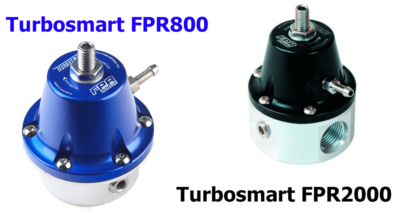
One last point; watching the differential fuel pressure is very instructive. If you have a decent pressure regulator like a Turbosmart FPR800 or 2000, the differential fuel pressure hardly moves at all; it’s very stable. If you see it move more than about 10 kPa then there’s some kind of a problem. We’ve been able to diagnose poor fuel pressure regulators on customers’ cars very quickly by watching this variable alone, and we highly recommend adding a fuel pressure sensor to any car that you’re tuning, for the simple reason that fuel pressure makes such a big difference, and as someone said… I can’t remember who, probably an American like Shane Tecklenberg, Greg Banish or Paul Yaw, if you don’t have data, you have an opinion!
Thank you.
©2018 Adaptronic