Setting up Launch Control and Drag Style Antilag

This article explains how to set up launch control and drag style antilag. Sometimes this is called “2 step” in keeping with the tradition of inaccurate and unspecific nomenclature like “dynamic compression” and “trailing throttle response”. These are really two separate functions with separate purposes, but often they are configured together and the term “2 step” is used to describe both of them by different people so we will discuss them both in the same article.
The first function is to control the launch RPM, so that when you launch the car you can have the optimum amount of wheel slip. Zero wheel slip (ie full grip) often does not allow the maximum acceleration because the engine falls out of its torque band, and too much slip (too much wheelspin) fails to get the power to the ground to accelerate the vehicle.
The second function is to build boost. A turbocharged engine will normally need some amount of boost to get off the line quickly, and holding the engine at a particular RPM with throttle, or ignition cut alone, generally won’t build enough boost. So to build boost, the EGT from the engine must be increased, so the way we do this is with a combination of ignition retard and ignition cut.
To use this function, you will need a vehicle speed sensor, so that the ECU can know to stop applying the ignition cut and retard once the car has got out of the hole.
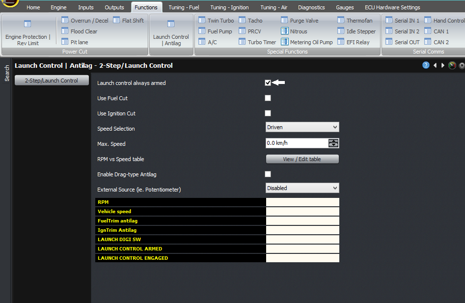
To enable it, go to the “Launch control / Antilag” screen within Functions -> Power Cut.
Select “enable launch control” to enable the function and see the settings.
Then assuming that you want to build boost, you will want to use ignition cut, and not fuel cut, so you should select ignition cut to be on and fuel cut to be off. The reason you would use fuel cut is if you have naturally aspirated engine which doesn’t mind having its fuel cut to control RPM, and you’re only doing it to control the launch RPM.
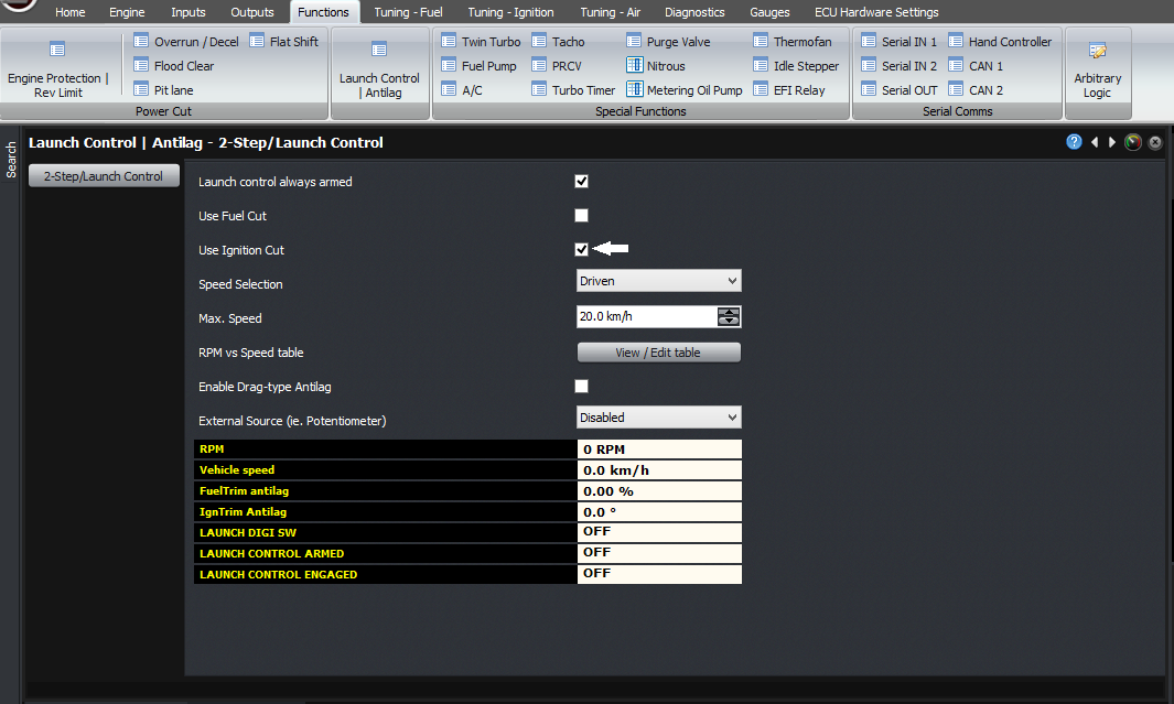
Enabled ignition cut
The next selection is “Speed selection”, in which you select how the ECU will determine vehicle speed. Ideally this would be taken from the ground speed, but to do this requires 4 vehicle speed sensors, rather than many installations which will only have a single sensor on the gearbox. If you only have a single sensor, then you must select “Driven” as the speed selection, but for obvious reasons, the RPM limit vs road speed table won’t have much of a meaning because the ECU will not know the road speed. If the RPM is too high and you only have the single sensor on the gearbox, then there’s no way for the ECU to know that the road speed isn’t high enough yet and the slip is too great.
The maximum speed is a setting above which the launch control or 2-step will not longer do anything.
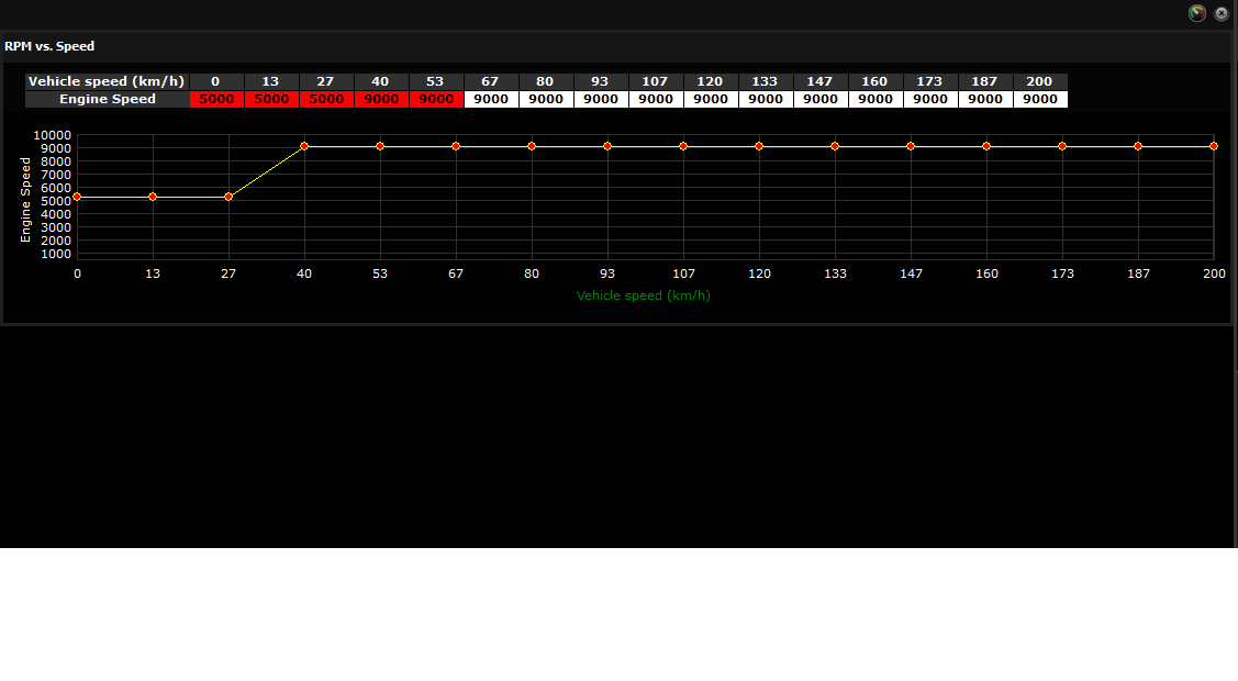
The next setting is the RPM vs speed table, which is the RPM limit as a function of the road speed. Now technically in a 2-step, there would be a fixed RPM below a certain speed, and then the RPM would not be limited about that speed. But using this system, it allows you to ramp up the RPM, if that’s what your application calls for.
 The
next setting is “enable drag-type antilag”, which if you’re
trying to build boost, you should enable.
The
next setting is “enable drag-type antilag”, which if you’re
trying to build boost, you should enable.If you enable the antilag function, the first setting is the RPM window. This is the RPM range over which the antilag feature is fed in, and the range over which the full ignition cut occurs. I’ll explain this in a second. The next settings are the amount of ignition retard (this should be a positive number), and fuel enrichment, during antilag.

Enabled drag style antilag
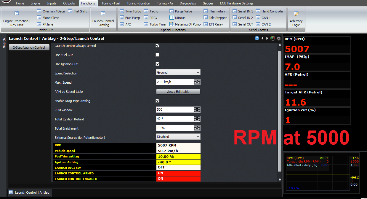
To pick an example, let’s assume our ignition retard is set to 40 degrees, the fuel enrichment is set to 10%, the RPM window is 500 RPM, and the RPM limit set in the RPM vs Speed table is set to 5000 RPM at the current speed.
Below 4500 RPM, the engine will behave normally. Then over the range of 4500 – 5000 RPM, the ignition will retard by 40 degrees and the fuel enrichment will go from 0 to 10%.
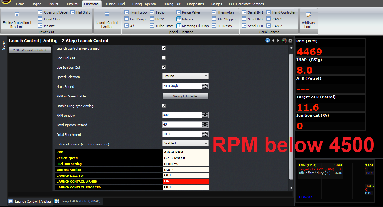
By 5000 RPM, the ECU will be applying the full ignition retard and full fuel enrichment.
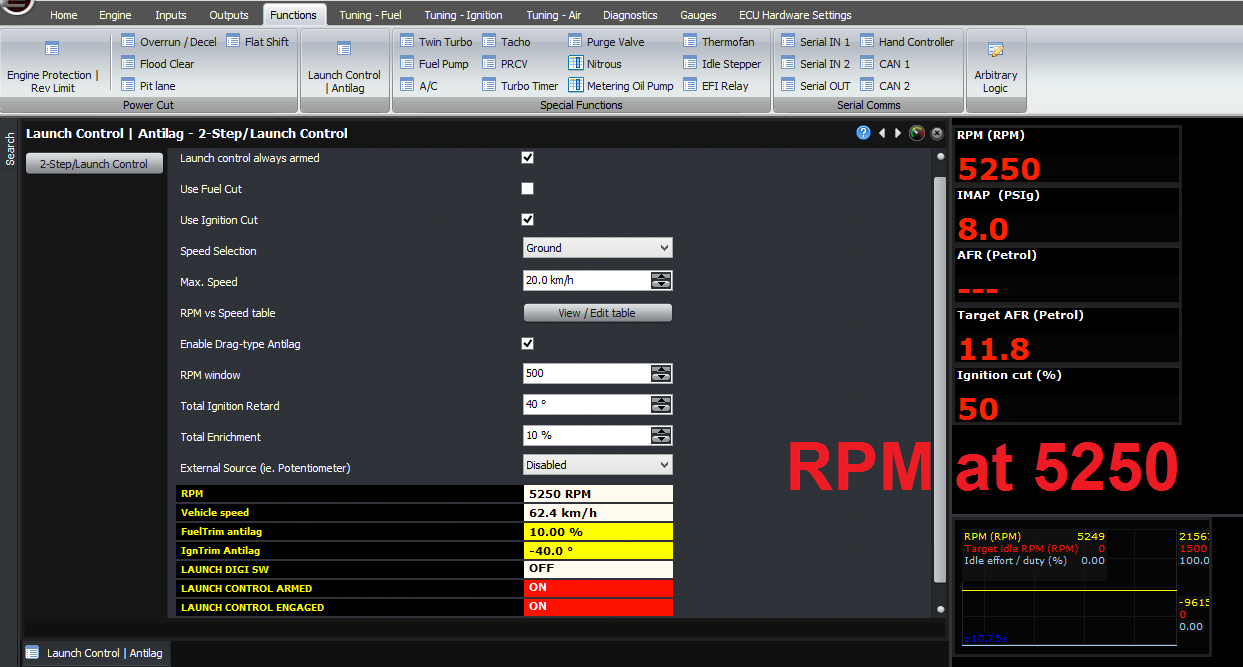
Then over the range from 5000 – 5500 RPM, the ECU will go from 0% ignition cut to 100% ignition cut. So at 5250 RPM for example, the ECU will be at 50% ignition cut, 40 degrees ignition retard with respect to the ignition map, and 10% fuel enrichment.
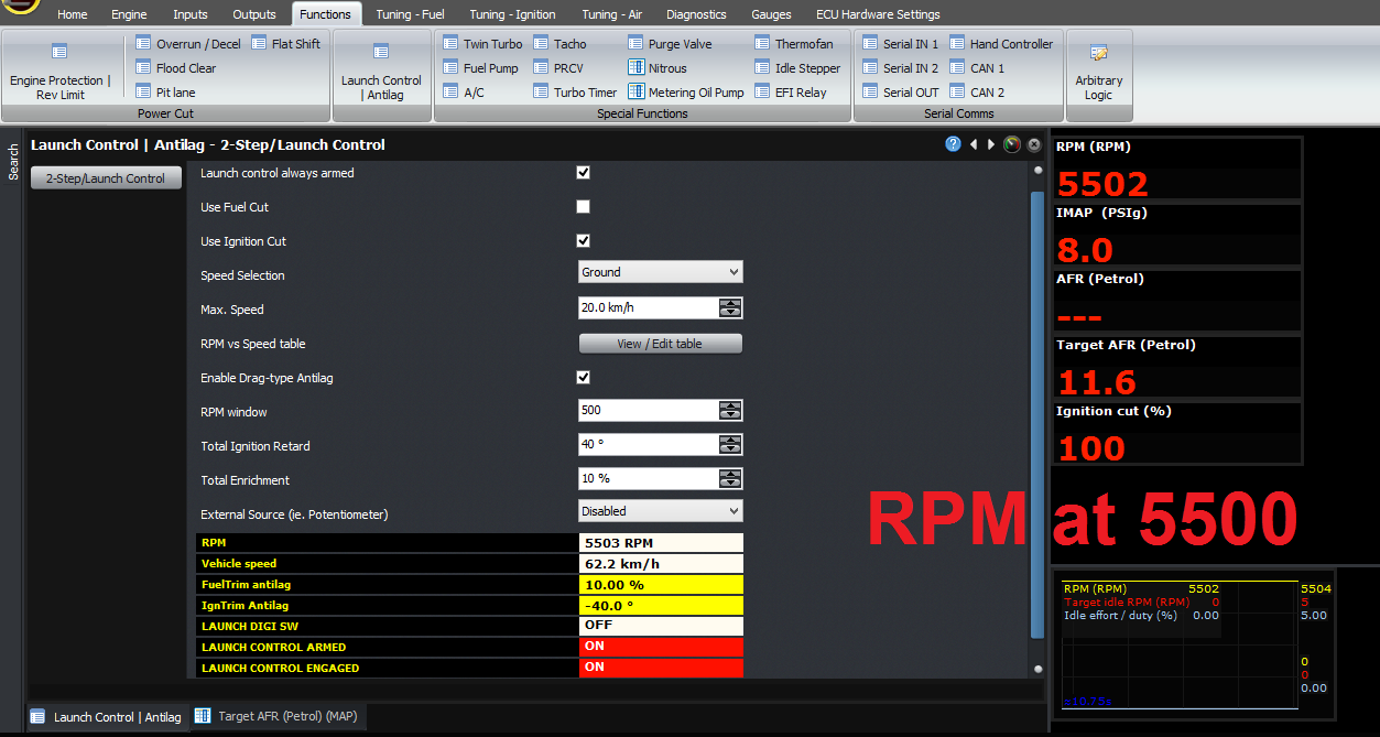
Like the other functions, you can see the current variables ont he main screen as it’s happening, and these are all logged in the if you’re logging at the time.
Thank you and happy learning!
©2018 Adaptronic