Wheel Speed Inputs & Gear Detection on Modular ECUs

Most cars have a tailshaft speed sensor mounted in the gearbox. This either connects to the ECU, or to the dash which then outputs a signal to the ECU. We need to be able to read road speed to perform functions such as idle control on some cars, launch control, gear detection and traction control.
Almost all the speed sensors you will find are magnetic in nature, but the technology varies between different sensors. As far as the ECU is concerned, there are two kinds of inputs it can accept; a digital signal that is pulsed to ground with a varying frequency, or a variable reluctance sensor which gives approximately a sine wave output whose frequency again varies with speed.
Both of these input types can be wired into the VSS input on the ECU, and this is done in the factory wiring of plug and play ECUs (assuming the car has a VSS from factory).
For the digital switch type sensor, you must select the type as digital in the wheel speed input settings. For the sine wave analogue type, you must select reluctor as the type.
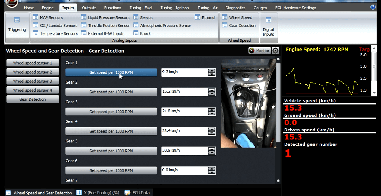
 Go
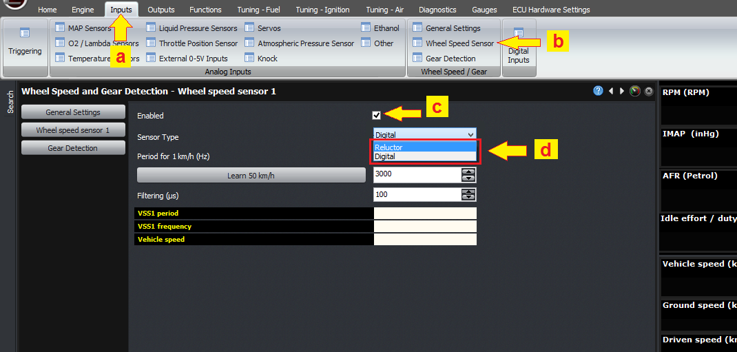
to (a) Inputs tab (b) select wheel speed (c) tick the check
box to enable wheel speed sensor (d) then select for the
sensor type (digital/reluctor).
Go
to (a) Inputs tab (b) select wheel speed (c) tick the check
box to enable wheel speed sensor (d) then select for the
sensor type (digital/reluctor).On some older cars, this digital signal is generated using a magnetic reed switch. A magnet on a rotating shaft causes the reed switch to close as the magnet passes it, which pulls the signal to ground. Because it uses mechanical contacts, they tend to bounce when they close instead of making a clean square wave. Therefore to use this kind of sensor, you may need to run a high value on the filter setting to filter out this contact bounce. Normally much lower filter settings can be used on Hall effect sensors.
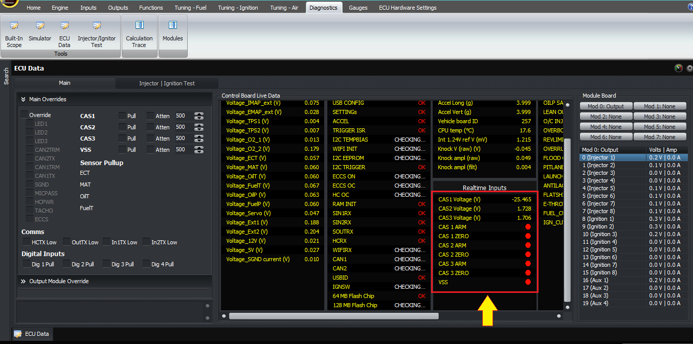
Once you have wired in the wheel speed sensor, you can verify that it’s working by checking the ECU data window in the software. As the wheel rotates, the VSS input should change state continuously, and it should keep the same state when the car is no longer moving.
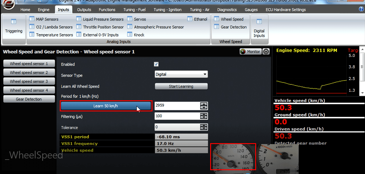
Assuming that this is working, the next step is to calibrate the road speed. If you have selected km/h as your speed units, the software will give you an option to learn the 50 km/h calibration value. In miles per hour mode, the target speed is 30 mph. To learn the speed, drive the car to this speed, and hit the “learn” button in the software. After this, the road speed should read accurately.
In a manual transmission car, you can now go through the different gears and learn them in turn. This does not require driving at any specific speed; simply drive in each gear with the clutch fully engaged (ie not slipping), and hit the “learn” button for that gear. The ECU then learns the ratio between the road speed and RPM and uses that to detect which gear is engaged. After this, the gear number in the gauges window should also read correctly when driving in that gear. This is useful in reviewing data logs, to gain context and driver training, but also to select different boost pressure in different gears.
On systems with individual wheel speed sensors, as required for traction control, the process is the same but the wheel speeds must all be learnt at the same time. If you have a two wheel drive car and you’re using a dyno to do the learning, then you can manually copy the calibration from the two driven wheels to the two passive wheels, assuming the front and rear wheels have the same type of tyre.
Thank you and happy learning!
©2018 Adaptronic