Configuring Input on Modular ECU

This article describes how to
configure inputs on your Modular ECU. In this article we will
discuss analogue and digital inputs, but we will exclude the
trigger / crank angle sensor inputs, wheel speed inputs, flex,
knock, or ethanol content. Also we will only discuss the
inputs available on a standard M2000 ECU with no expansions.
Here is the list of the inputs we will discuss:
Here is the list of the inputs we will discuss:
Manifold pressure:
The ECU can measure the intake and exhaust manifold pressures, as well as barometric pressure. The M2000 ECU has two internal MAP sensors, and supports two external MAP sensors. The minimum you will need is intake manifold pressure, as this is part of the fuel model. For a dual bank engine with separate intake manifolds for each bank, for example most V12 and some V6 engines, you can run a separate MAP sensor on each manifold and control the fuel to each bank separately. You will have already set the “separate banks” selection when you set up the engine initially, so that will already be set. If you are running separate banks, you will need to configure both of the intake MAP (IMAP) inputs; if you are running a single bank engine then you only need to do 1 IMAP configuration.
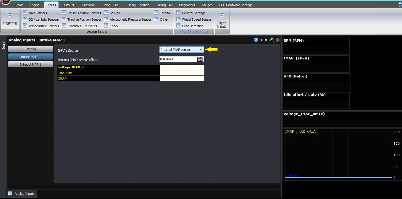
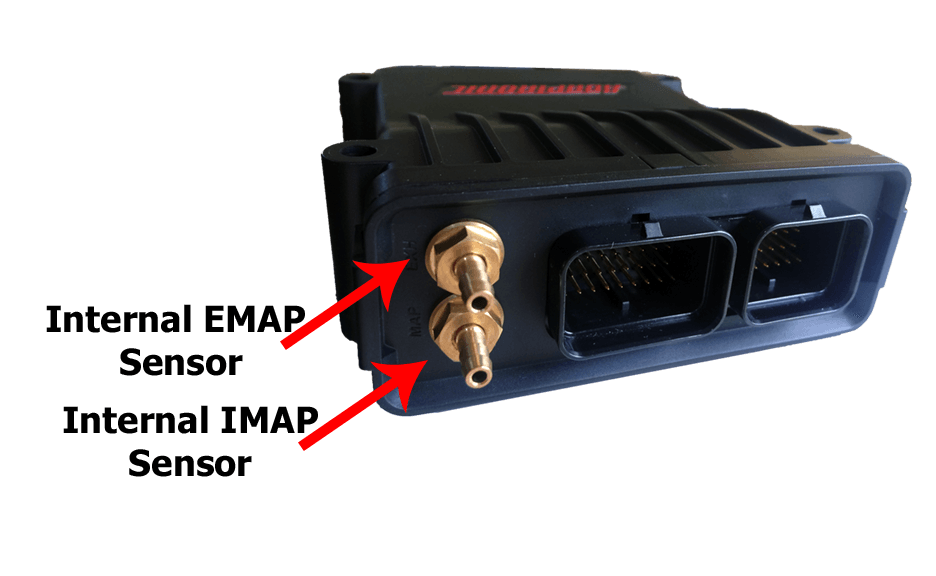
The first thing to configure is the source for the MAP sensor. Your choices are either one of the two internal 4-bar MAP sensors, or an external input with a separate MAP sensor wired in. The M2000 and small box ECUs have the intake MAP as the lower port, whereas the upper port is called the EMAP sensor. Note that both sensors are identical, so you can use either one for intake MAP.
 If
you’re using an external sensor, then you need to calibrate
the sensor, or select the calibration from the list of
preconfigured system.
If
you’re using an external sensor, then you need to calibrate
the sensor, or select the calibration from the list of
preconfigured system.After doing this for the 1 or 2 IMAP inputs, you can decide if you’re going to run exhaust MAP sensors as well. If so then you configure them in the same way as the IMAP sensors. I need to tell you that measuring EMAP is much harder than IMAP. If you’re going to use one of the built-in MAP sensors on the ECU, then the signal must be run through a canister filled with steel wool or similar to prevent water and fuel from getting into the MAP sensor. The hose from the canister to the ECU must come from the top of the canister. For some applications this still won’t be robust enough and a stainless steel sensor, the sort that would be used for fuel or oil pressure, should be used instead and wired in to the external IMAP or EMAP input signal pin.
 Sample
of EMAP Cannister
Sample
of EMAP CannisterIf you like, the second IMAP input can be used for diagnostics, for example measuring the post-compressor boost so you can detect the pressure drop across the inter-cooler.
Lastly, there are some global settings for the MAP sensor filtering. This is required because the intake manifold pressure actually changes as each cylinder or rotor does its intake stroke. The unfiltered IMAP signal actually looks like this; this was taken from a 6 cylinder engine at idle.
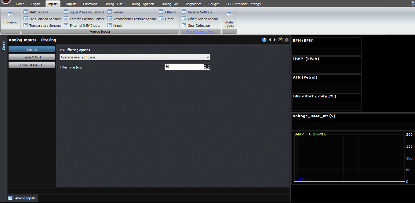
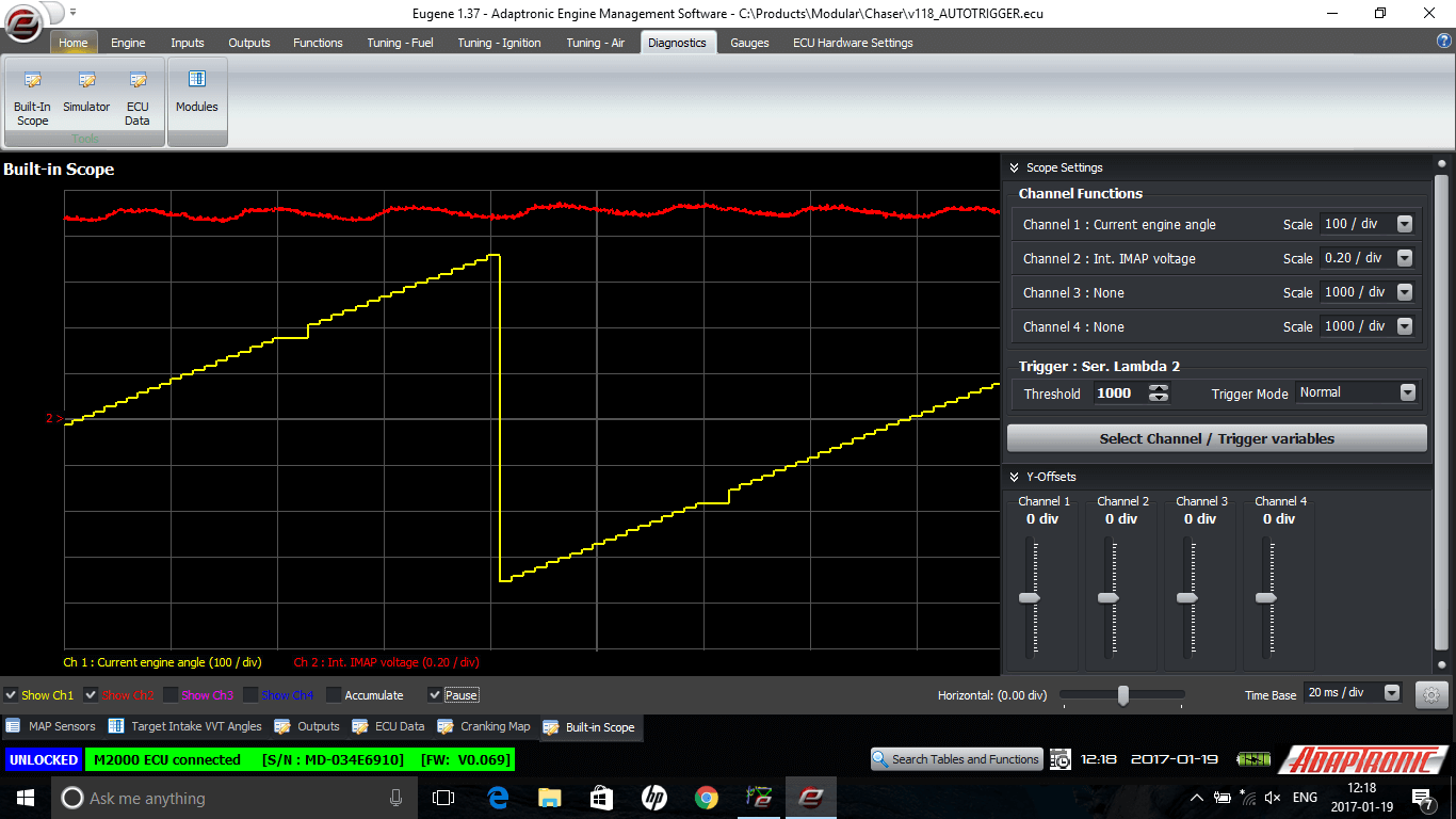 What
the ECU can do is to average the MAP signal over each
induction stroke, for example every 120 degrees on a 6
cylinder inline. If you were to use a standard V8 engine with
a single plenum, then you would select 90 degrees as the
averaging period. If you had a flat-plane V8 with a separate
plenum for each bank, then each bank would do an intake stroke
every 180 degrees, so you would select 180 degrees as the
filter period. A similar effect happens with exhaust
pulsation.
What
the ECU can do is to average the MAP signal over each
induction stroke, for example every 120 degrees on a 6
cylinder inline. If you were to use a standard V8 engine with
a single plenum, then you would select 90 degrees as the
averaging period. If you had a flat-plane V8 with a separate
plenum for each bank, then each bank would do an intake stroke
every 180 degrees, so you would select 180 degrees as the
filter period. A similar effect happens with exhaust
pulsation.Barometric pressure measurement is a separate issue. Some ECUs have an internal MAP sensor, but for obvious reasons you can’t have a waterproof ECU with an internal MAP sensor. So the options instead are to either:
1) Use the other built-in MAP sensor that you’re not already using for tuning
2) Have the ECU measure the MAP before the engine starts
3) Use an external barometric pressure sensor, for example a MAP sensor, wired in to the IMAP or EMAP port; this must be configured and calibrated.
4) Use a fixed pressure value
Note that the ECU does not use barometric pressure as part of the tuning algorithm, because MAP at wide open throttle changes with barometric pressure. For the changes in back pressure affecting the VE, the IMAP / EMAP tuning method automatically deals with this. The only reason for the ECU using barometric pressure is to convert between gauge and absolute pressure sensors, for example to measure fuel pressure which we’ll talk about in a second.
The other thing you can enable is a time based filter, which helps filter out some other effects due to asymmetry of the plenum; 0 to 50 ms are typical values.
Liquid Pressure Inputs:
The next thing we’ll talk about is fuel and oil pressure sensing. The M2000 has dedicated input pins for fuel and oil pressure, and as you’ve probably seen in other articles or videos, measuring fuel pressure and using that as part of the fuel modelling algorithm makes life a lot easier for the tuner and also safer for everyone.
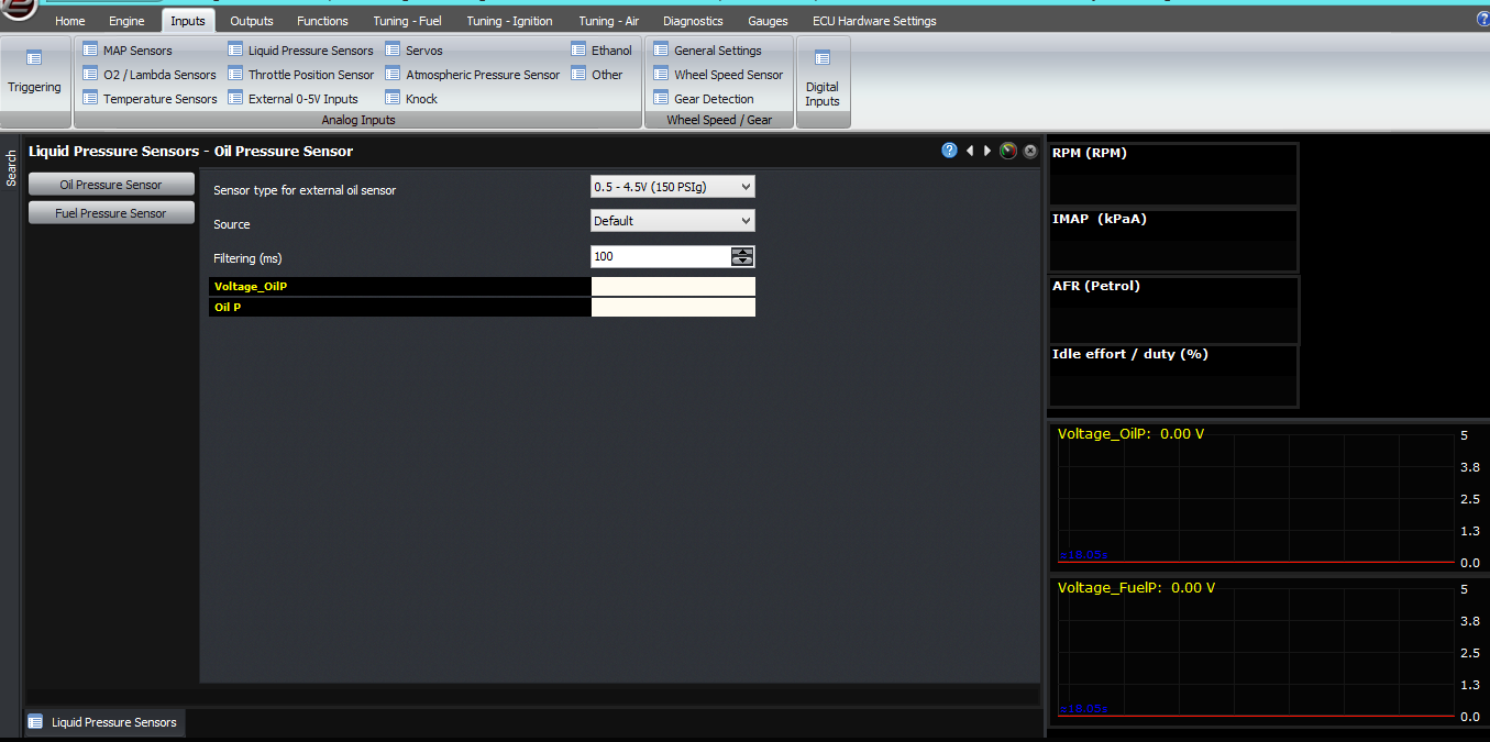
So for fuel and oil pressure, you must select firstly the sensor that you’ll be using – the 150 PSI gauge pressure sensors being the most common. You can also specify a filter time similar to the time based filter on the MAP sensor, for example 50 or 100 ms. You can also specify different input pins if you need to, but we recommend people to leave the default connection.
Now let’s discuss temperature inputs. The M2000 and the plug-in ECUs have 4 temperature inputs, which are named coolant, air, oil and fuel temperature. Coolant and air are used as part of the tuning algorithm. Oil is used for monitoring, alarms and safeties only. Fuel is used as part of the tuning algorithm if the “trim for fuel density” option is selected in the fuel output control section.
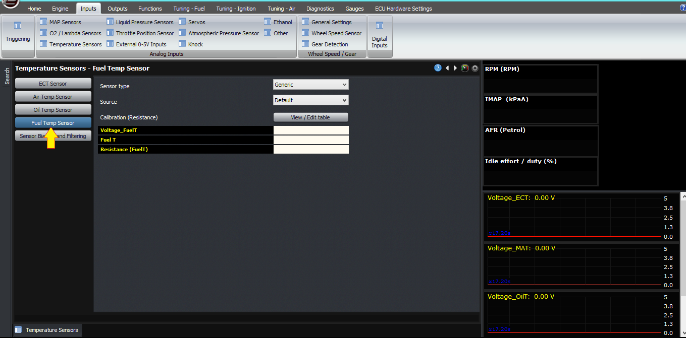
The 4 temperature inputs each have 2 bias resistors in the ECU, so the ECU can select one of three different pullup resistor values (one, two or both) and the ECU automatically selects the one that gives the best for the current sensor resistance. The ECU then calculates the resistance from this and looks it up against the calibration. So you can select a predefined temperature calibration, or you can enter your own calibration, but the values are resistances; not voltages, ADC counts or another measurement. So for each of the sensors, you must select either that there’s no sensor selected, or select the sensor type. You must also select the input source for that sensor, again we suggest people use the default input pin for this.
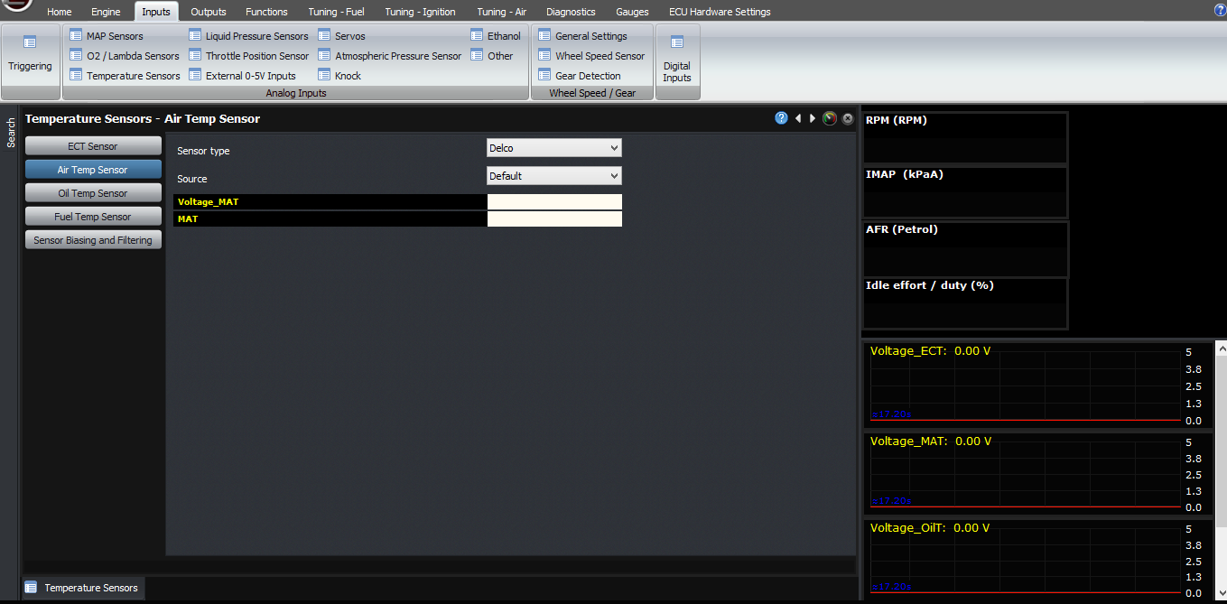
For each of the input pins, you can also select the filter time. Note that this filter is applied to the pin, not to the sensor channel. So if you are reading air temperature from the fuel temperature pin, you must select the filtering on the fuel temperature pin.
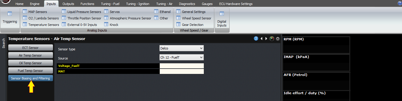 Change
the source to FuelT
Change
the source to FuelT Then
adjust the filtering in Bias FuelT Sensor Input pin
Then
adjust the filtering in Bias FuelT Sensor Input pinThe final option is if you are using an external pullup resistor, or piggybacking the sensor with a factory ECU that has its own pullup resistor. In this case you need to disable the sensor bias, but in this case the input is calibrated in Volts, rather than resistance (because the Adaptronic doesn’t know the pullup value in the factory ECU)
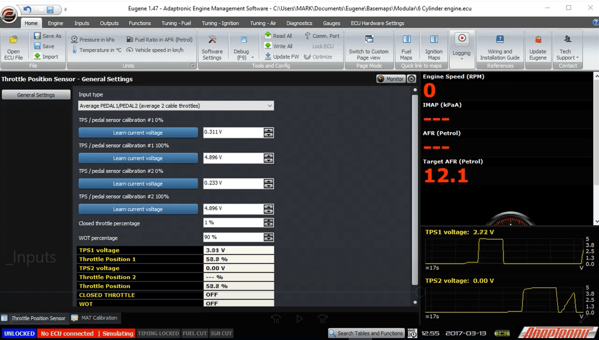
Throttle Position
Throttle position inputs are the next one that we will talk about. In this article we’ll only discuss cable throttle systems because we’ll cover electronic throttle in a separate article. We recommend setting the selection to “default”, and in this case the ECU knows it’s cable throttle because there are no DBW modules installed, and it only reads the TPS1 input. You can also set it up to average the TPS1 and TPS2 inputs if you like.
To calibrate the TPS inputs, firstly close the throttle, and then click on the Learn for TPS 0% on TPS 1. Do the same on TPS 2 if you’re using a second sensor. Then open the throttle all the way to 100% and click learn on the 100% TPS voltages. Note that on some cars like the RX7 FD, a wax pellet holds the throttle open at low coolant temperatures, so this must be done with the engine at operating temperature on such cars.
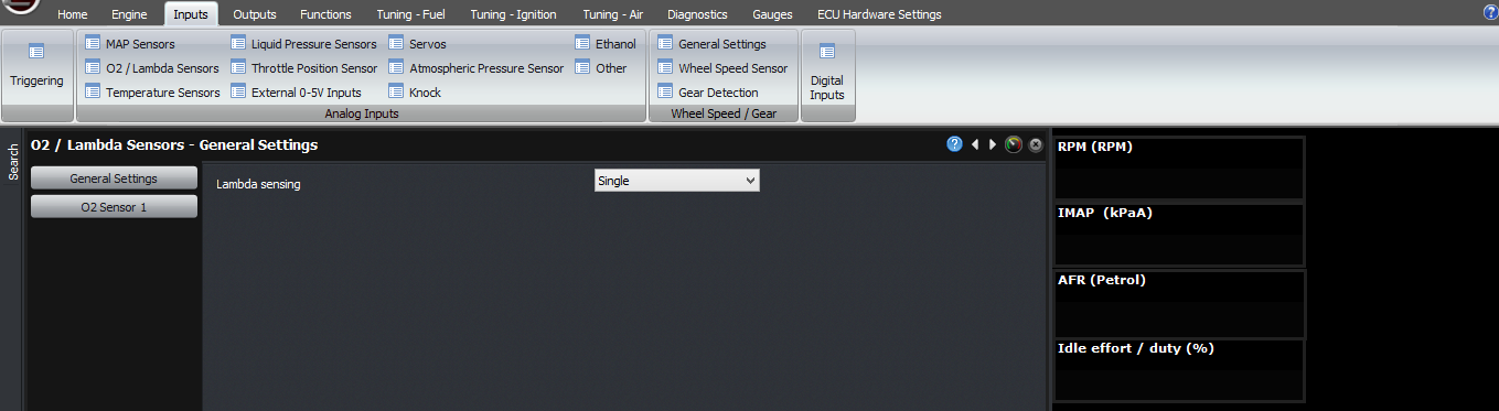
Lambda:
Lambda sensing is complex because there are many ways to do it. The first thing we need to select is the lambda sensing method we will use. The first is single, where you are using a single lambda sensor only. The second is average, where you run two, or multiple, lambda sensors, but the ECU averages them and gives you the average as the lambda reading, and that’s what’s considered for closed loop fuel and leanout safety protection. The third is individual, where you have a separate lambda sensor for each bank or cylinder, and each bank can have separate fuel trims.
Note that even if you are averaging the sensors, you can still see the individual value from each sensor on the laptop, and they will be logged individually as well, but the closed loop control and safeties will use the average.
You can also run individual lambda on each cylinder, and if so, the ECU will average all the lambdas for that bank to give the overall lambda reading, for the bank trim. For example on a V engine numbered with odd and even banks, the ECU can average the odd lambda values and the even lambda values. But as I mentioned before, you can still see the individual lambda for each cylinder.
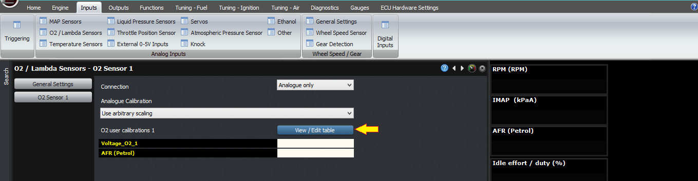
The first, and most simple way, is to connect the oxygen sensor, or sensors, into the O2 input or inputs on the ECU. If you’re doing this, then select the lambda sensing option as being analogue only. Then select the type of input from a list of precalibrated sensors, or you can enter your own calibration.
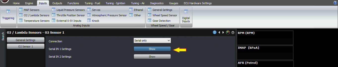
The second way is to use serial. For this, select “serial only”. In this case the ECU will read the lambda only from a serial port. But in this case you need to also configure the serial port. For the more simple products like the Zeitronix, AEM and so on, just select the correct protocol on the appropriate serial in port. The ECU has two serial input ports, which are functionally the same so they can be used interchangeably. So for example, on a V engine, you can run a Zeitronix sensor on each bank, by selecting both serial inputs as Zeitronix, connecting the odd bank sensor into serial port 1, and the even bank sensor into serial port 2.
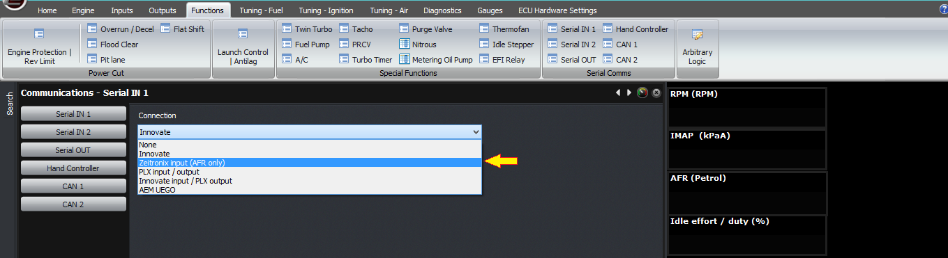 The
Innovate sensors are more complex because they can be daisy
chained, however the in-band MTS serial output doesn’t contain
the configuration of the system. The ECU can accept several of
the integrated combination gauges, for example the SCG, ECF
and so on. I won’t list them here because they’re continually
being updated. If you’re not using one of these integrated
lambda with another function gauges, then select “none” for
this input. The other setting that needs to be set is the
number of individual lambda channels, which includes the LC2,
MTX-L and the older LC1 sensor controllers.
The
Innovate sensors are more complex because they can be daisy
chained, however the in-band MTS serial output doesn’t contain
the configuration of the system. The ECU can accept several of
the integrated combination gauges, for example the SCG, ECF
and so on. I won’t list them here because they’re continually
being updated. If you’re not using one of these integrated
lambda with another function gauges, then select “none” for
this input. The other setting that needs to be set is the
number of individual lambda channels, which includes the LC2,
MTX-L and the older LC1 sensor controllers.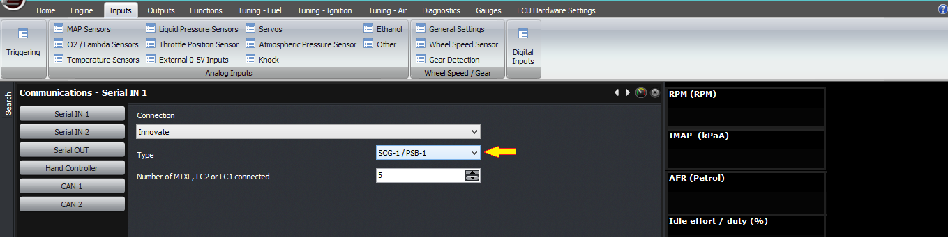
Any other channels not included in these just mentioned are considered to be EGT inputs, via the Innovate TC4 thermocouple amplifier and input device.
The “serial overrides analogue” selection will use the serial input if available, but if it’s not available then the analogue input is used instead.
Very soon we will have a CAN input option as well, for that there will be additional settings to select the pre-programmed CAN channel definition for example the Motec PLM.
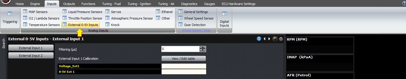
External 0-5V:
There are three more inputs which can be configured as generic 0-5V inputs; if you’re using additional sensors for logging inputs which are not part of the ECU calculations, they can be calibrated in this section.
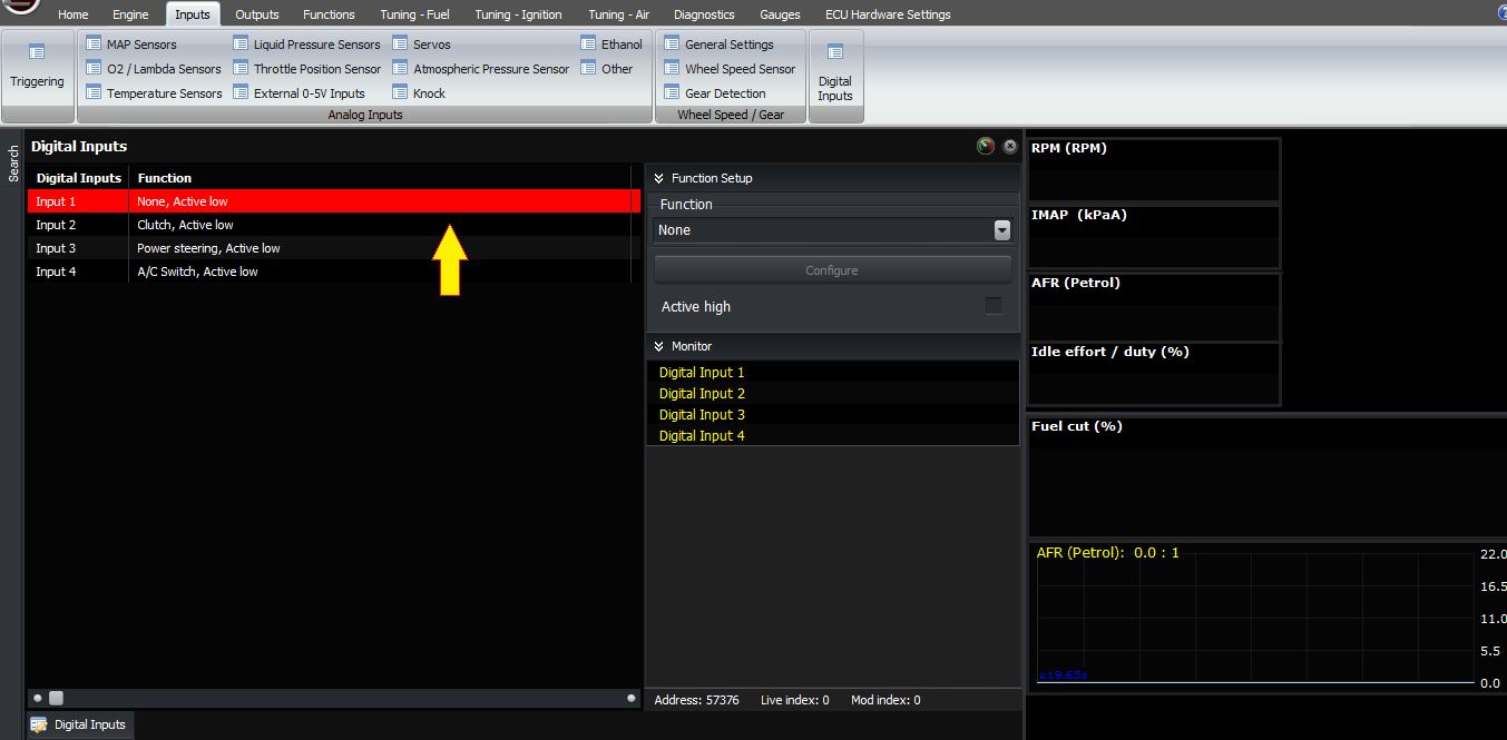
Digital Inputs:
Finally, we’re going to discuss the digital inputs.
For each digital input, you can select “none”, or the function of that digital input. In general, we will discuss the function of these digital inputs in the respective article for that function.
Thank you and happy learning!
©2018 Adaptronic