Setting up Auxiliary Outputs on Modular ECU

First I’ll explain about the types of outputs in terms of hardware, because that might affect how you select them.
Most auxiliary outputs on ECUs switch to ground, with the positive voltage supply provided to the load externally. This is basically because of the way transistors are made; switching to ground is a lot easier and cheaper than switching to power.
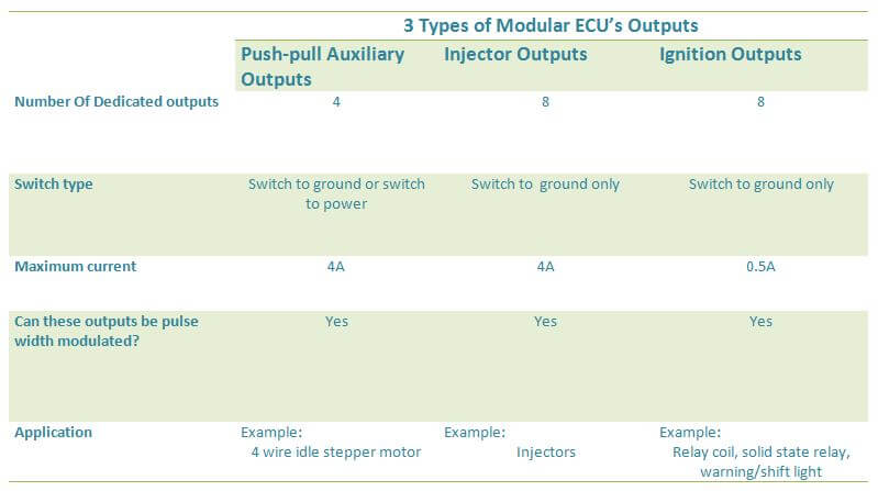
The Modular ECUs have three types of outputs.
The first is what we call a push-pull auxiliary output. All 4 of the aux outputs on the M2000 are of this type. These can switch to ground, or switch to power. Any load that requires being switched to power will need to use this type, and that includes bipolar (or 4-wire) stepper motors. For example if you’re intending to run a 4 wire idle stepper motor on an unexpanded M2000, you will need all 4 auxiliary outputs for the idle control motor. This output can source up to 1A, and sink up to 4A. The actual transistors are rated at higher currents but this is where we have set the limit so that there’s margin. These outputs can be pulse width modulated.
The second is an injector output, which can be used as an auxiliary output. In this case, the output can only switch to ground, not switch to power. The maximum current we allow it to sink is 4A, same as an auxiliary output. These can be pulse width modulated also.
The third type is an ignition output, which can be used as an auxiliary output. Again the output can only switch to ground, but the maximum current is much lower at 0.5A. This means it can be used to trigger a relay coil, solid state relay, warning / shift light and so on. This output can be pulse width modulated, but usually the actuators that you’d want to pulse width modulate would require more current to drive, for example idle or boost control valves. One example of where this would be useful is to pulse width modulate the trigger input to a solid state relay.
 Summary
Table
Summary
TableIf you expand a Modular ECU with a mini Aux Output module, then that comes with 6 push-pull auxiliary outputs, so they can be used to drive 4-wire idle motors or pretty much whatever you like.
Now, an auxiliary output can be configured to be one of the preprogrammed outputs in the ECU, or you can implement your own based on any variable in the ECU.
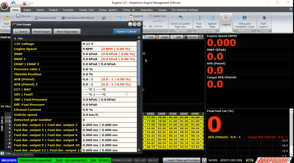
I should explain variables in the ECU at first. There are about a thousand variables built into the ECU. You can see these on either the live gauges, you can add them to the monitor panel, you can watch them in the buit-in scope and you can see them in the logs. They are separated into different categories to make them easier to find, and if you can’t find one then you can type into the search tool and see variables which include the string you’ve typed.
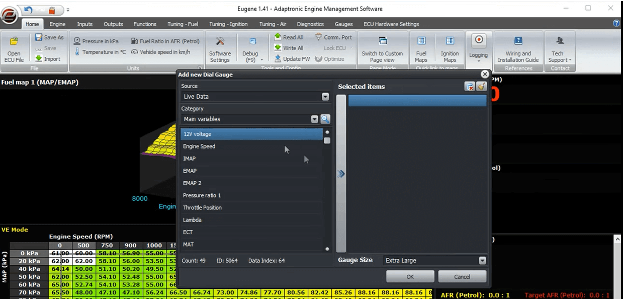 Monitor
Panel (Right click on monitor panel then add new gauge)
Monitor
Panel (Right click on monitor panel then add new gauge)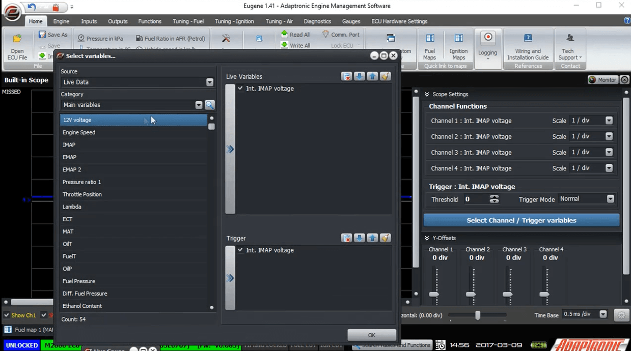 Simulator
(Shortcut key -F4)
Simulator
(Shortcut key -F4)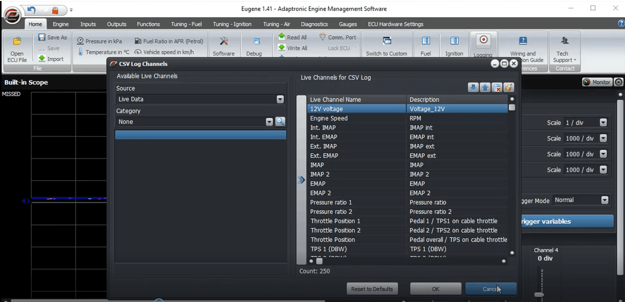 Logs
(Go to logs and select CSV Log Channel)
Logs
(Go to logs and select CSV Log Channel)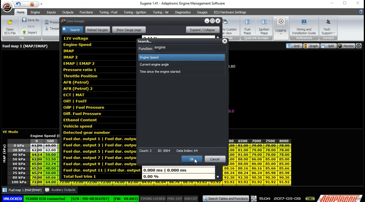
In live gauge window you can click the search button and type-in the variable your looking for.
I’ll start first with preprogrammed outputs. These are output functions that the ECU decides based on built-in logic, the settings you enter and the conditions. For an output that’s going to be a simple on/off function, these values either show 0% or 100% and this value refers to the duty cycle (representing off and on, respectively). These include functions such as thermofan, air conditioning compressor, fuel pump and also stepper motor drive phases.
Other prepregrammed outputs have variable duty cycles which vary from 0 to 100%. These include idle valve duty cycle, boost control duty cycle, VVT control valve duty cycle and so on.
Let’s have a look at the output screen in Eugene. In this screen, all the outputs on the ECU are listed, in accordance with the modules that have been installed in the ECU.
On a base model M2000 for example, there are 20 outputs; 8 injection, 8 ignition and 4 auxiliary push-pull.
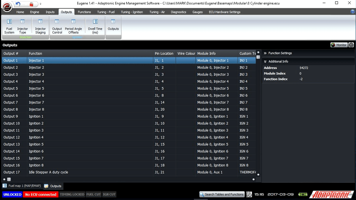
 8
ignition; 8 injection;4 auxiliary push-pull
8
ignition; 8 injection;4 auxiliary push-pull If you have a configuration that only uses 6 injector outputs, for example an in-line 6, or a 3-rotor with 2 injection stages, you will see that injector outputs 1-6 can not be changed, but injector outputs 7 and 8 can be modified in the settings.
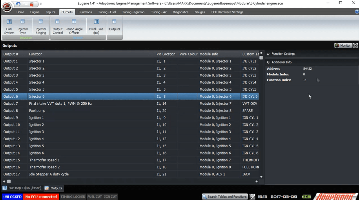 Injector
6 cannot be change.
Injector
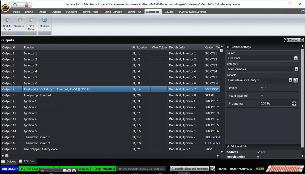
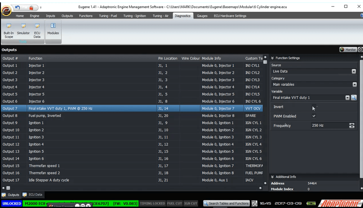
6 cannot be change.For argument’s sake, let’s assume that we want to configure injector output 7 to be an idle valve pulse width modulated output that oscillates at 250 Hz. What you would do is select the output, and change the type. Do this by selecting “outputs” from the variable category and choosing “Idle effort”. Then enter the frequency of 250 Hz, and the job is done. The procedure is the same for selecting a boost control output, although for one of those you would generally run a lower frequency eg 30 Hz.
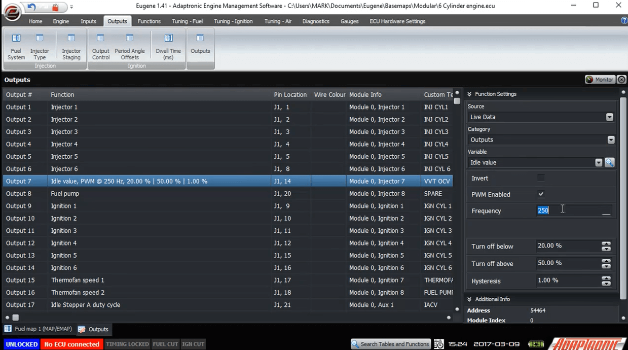 Output
7 configured
Output
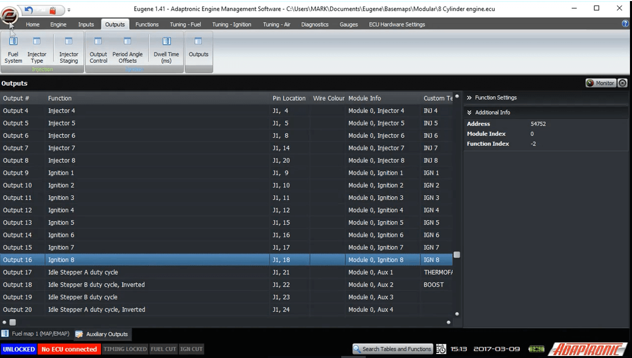
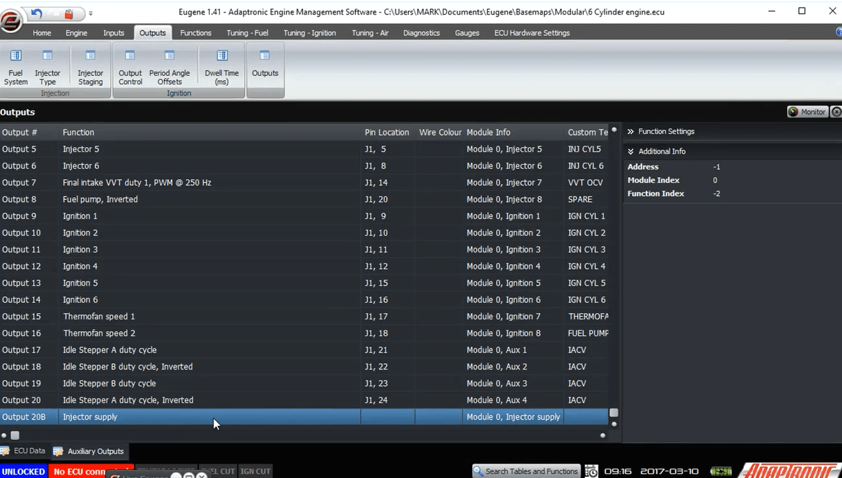
7 configuredLet’s do a more complex example now. Let’s assume that we want to configure auxiliary outputs 1-4 as push-pull outputs to drive a 4 wire stepper motor. In this case we would go to the first output, and select it as Idle Stepper A. We also need to enable Drive High to enable the output to be able to supply current, rather than just being a short to ground. The next output needs to be the complementary of this to drive the other end of the coil, so in this case we select Idle Stepper A, drive high again, but this time we also select “invert” so it drives with the opposite phase to the previous output. We then do the same for the following 2 outputs for Idle Stepper B.
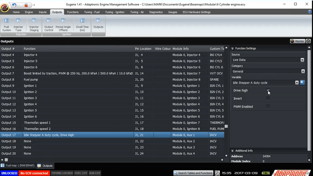 Output
17 Stepper A
Output
17 Stepper A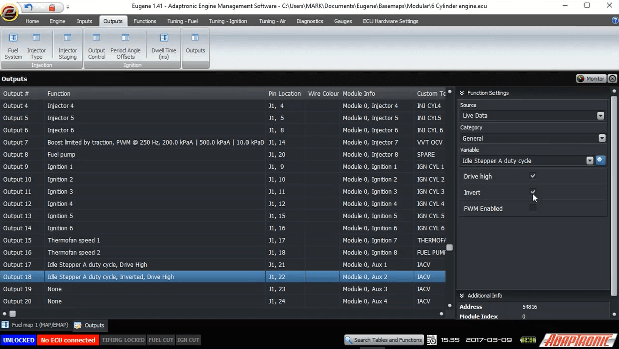 Output
18 Stepper A
Output
18 Stepper A This way, each coil gets both ends energized in the right sequence.
For a 6 wire stepper motor, the procedure is the same except that you do not enable the “drive high” selection. Because of this, you are also free to use ignition or injector outputs to drive a 6 wire stepper motor; it does not need to use push-pull outputs. The same wiring and setup process is used for other 6 wire stepper motors for example metering oil pumps.
Let’s look now are a generic, input based output. In this example we will use an on-off style VVT, for example as used on the RB25 or 4AGE engines. If you’ve played with VVT you’ll know that in general the intake cam must be advanced in the midrange, but above about 5000 RPM the cam needs to be returned to its home position. For the sake of an example, let’s say that we want the output to come on between 2000 and 5000 RPM, with 100 RPM hysteresis. Ie, as the engine accelerates from idle, it will turn the output on when the RPM exceeds 2000, but it must go below 1900 for the output to turn off again. Similarly above 5000 the valve will turn off, and to turn back on the RPM must all below 4900.
You configure this firstly by selecting the variable from “main variables” rather than “outputs”. The variable that you want is obviously “engine speed”. Enter the “off below” as 2000 RPM, and the “off-above” as 5000 RPM, and the hysteresis as 100 RPM. Disable PWM on the output, and the job is done.
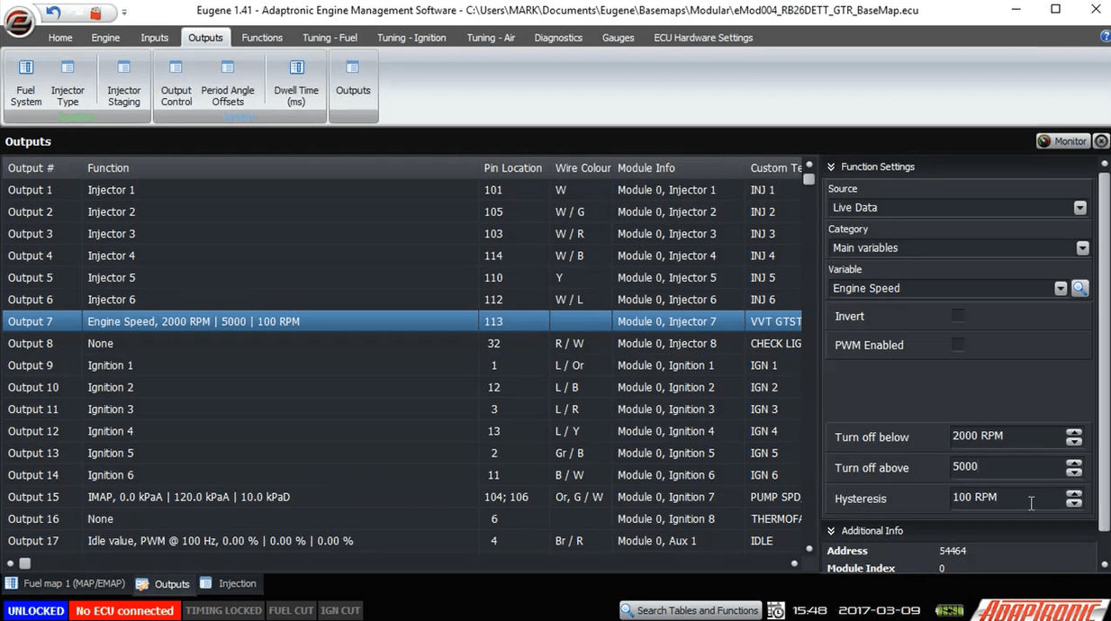 Configured
engine speed.
Configured
engine speed.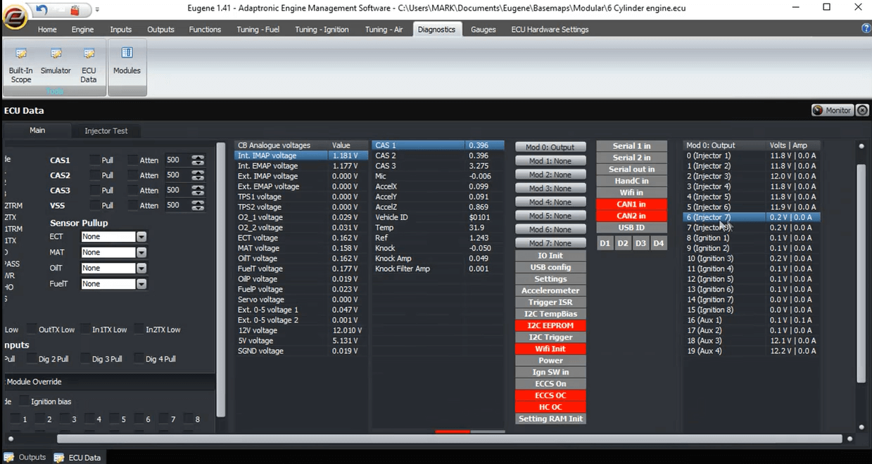
If you want a simple threshold, for example an auxiliary fuel pump to come on above a certain MAP value (above a certain boost), you can do this by just selecting the “off below” as your turn-on threshold (eg 130 kPa or 5 PSI), and make the “off above” very high so that you don’t ever see it (eg 500 kPa).
There is also a shortcut here which tells you which pin this output controls on the ECU connector, and how it is described in the pinout page. You can double click on that to take you to the wiring page so you can make sure you keep that up to date as you add another output.
Just
double click the output row.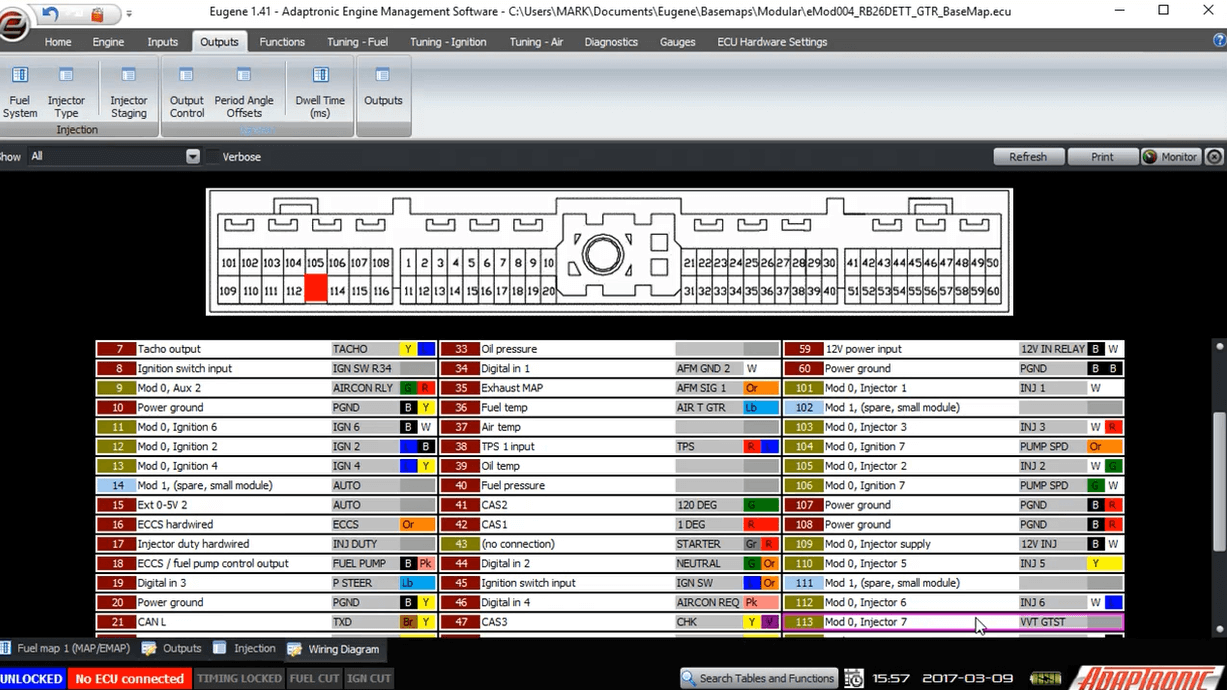 Wiring
pins.
Wiring
pins.To check that an output is working, there are a few ways to do it. The easiest is to go into the auxiliary output setting and click the invert on and off and verify that the output turns off and on.
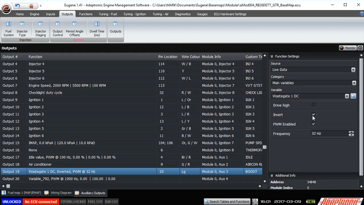 Click
invert on/off
Click
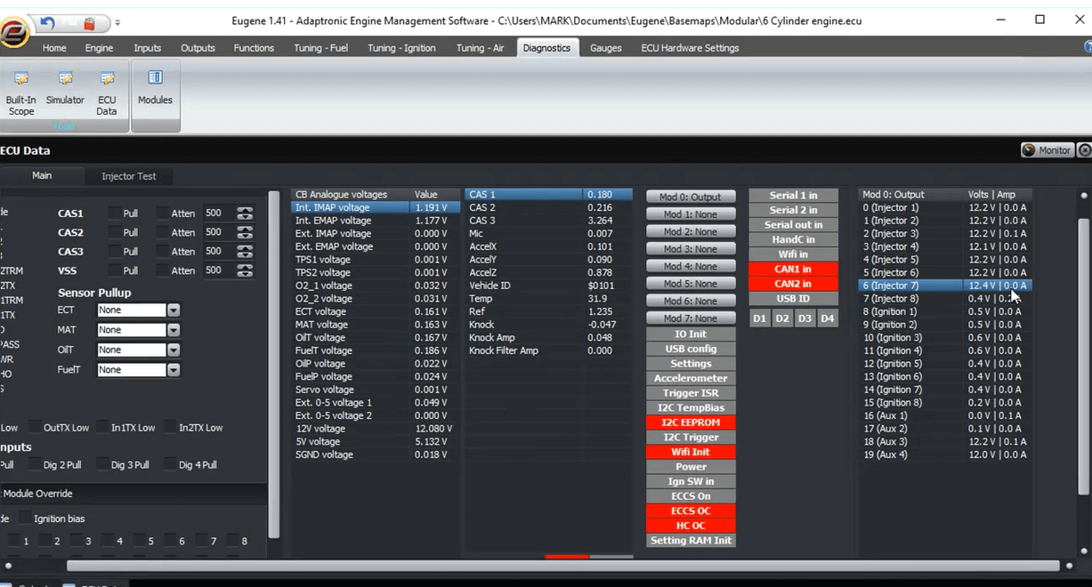
invert on/offA second way is to go into the ECU data page, and look at the output voltage and current. If an output is off, then its current should be close to zero, and if there is a load connected with 12V on the other side, then you should see the 12V on the auxiliary output pin, and in the diagnostic window. When you turn the output on, this voltage should go to near zero, and the current should increase to represent the current drawn by the load. This way you can tell if the load is connected and if it’s drawing the approximate correct amount of current.
 When
invert check box is off output voltage on diagnostic window
will show 12V. When
invert check box is on output voltage on diagnostic window
will show 0V.
When
invert check box is off output voltage on diagnostic window
will show 12V. When
invert check box is on output voltage on diagnostic window
will show 0V.One final point about the outputs page; because the injector outputs are switching mode, they need to recirculate the current back to the injector supply. If they recirculate the current back to another 12V supply then you end up with a large current loop and corresponding electrical noise. So this is why we show injectors powered from the ECU power in the M2000 wiring diagram. On some cars, the injectors are hot all the time, and on plug and play ECUs for those cars we connect the injector flyback connection to the injector supply, rather than to the 12V supply inside the ECU. This injector flyback connection is also shown on the outputs page, not so that you can change anything, but so that you can see which pin it connects to
Thank you and happy learning!
©2018 Adaptronic