Wiring and Configuring Outputs on Different Types of Idle Actuators using Modular ECUs

In this article I’m going to describe the different types of idle actuators, how to wire them to a Modular ECU and how to configure the outputs in the software. I will not be discussing how to set up open or closed loop idle, there will be other articles for that.
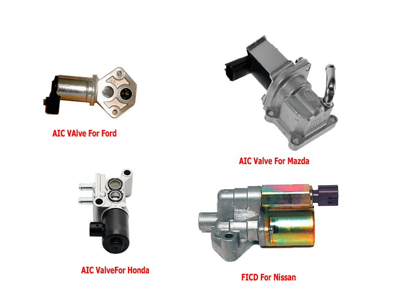
Firstly, let’s describe the different types of idle actuators. There are four types that we support. There may be others which might work using these methods, but these are the most common and the ones we support.
The four types can broadly be categorised by the number of pins on the connector; 2, 3, 4 and 6.
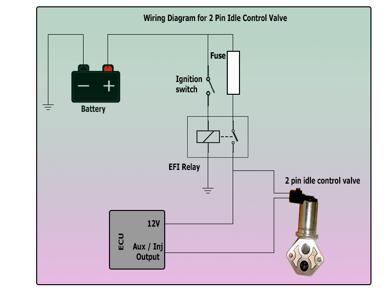
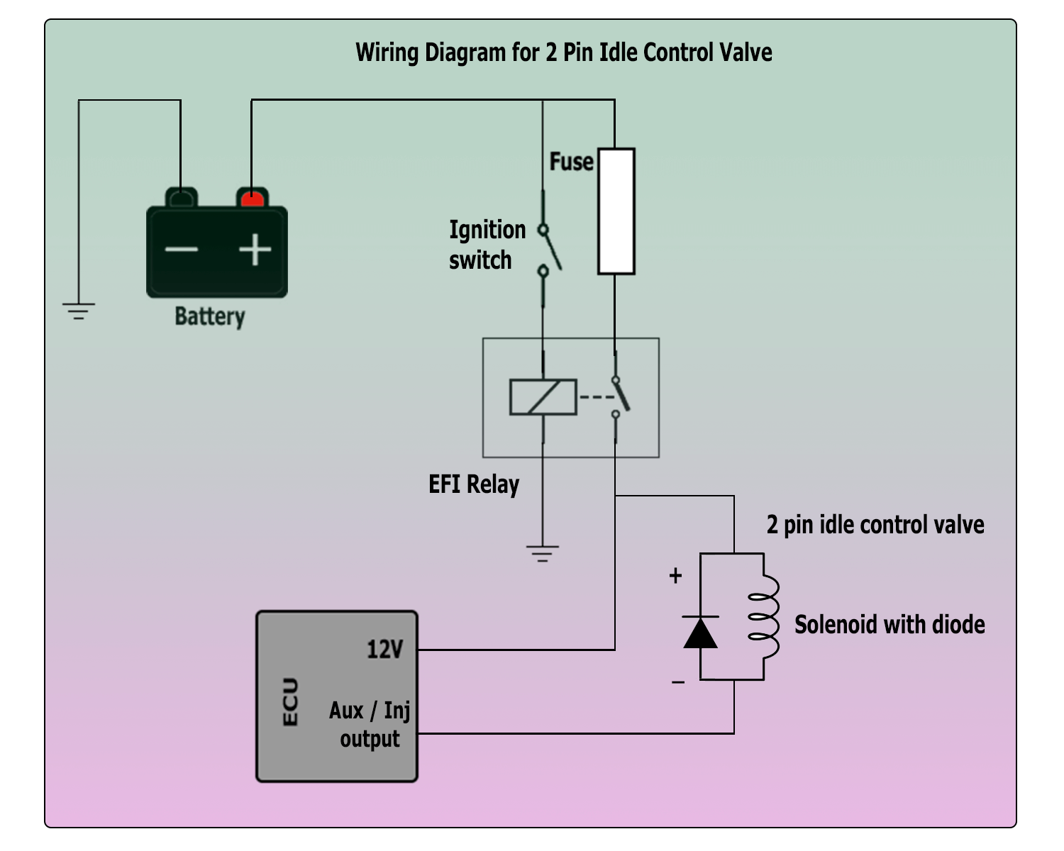
The most basic type is the 2-wire solenoid. These can be found on many Fords, Mazda, Nissan and Honda engines. Normally one side is connected to a 12V supply, and the other is pulled to ground by the ECU when it is to be activated. Sometimes these will have an internal diode; if so then you have to get the polarity correct or you’ll blow up the ECU output, or the internal diode, or both. If in doubt, check the factory diagram for which pin is positive and which is negative.
In almost all cases, these can be pulse width modulated to vary the amount of air going into the engine and thereby control the idle speed. To connect one of these to the ECU, one side must be connected to an ignition switched 12V supply, and the other side must connect to a high current output on the ECU, ie either an auxiliary output or an unused injector output.
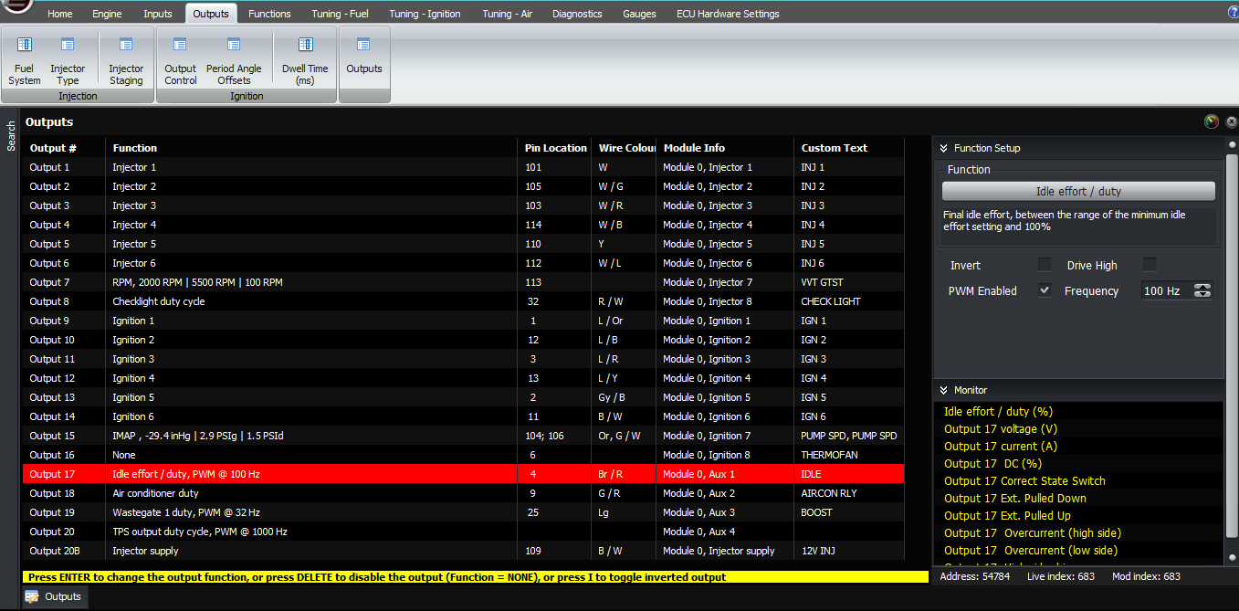
The output then needs to be selected as Idle Effort, PWM. The PWM frequency may take some experimenting if you don’t already know what it’s supposed to be. If the PWM frequency is too high, then the current going to the valve can be very smooth, so a small increase in the duty cycle will mean only a small increase in the current. Sometimes the valve can get stuck at a particular position, with the result that small movements are impossible. So a lower PWM frequency causes the valve to wiggle a little bit and prevent it from getting stuck in one place. Therefore, lower PWM frequencies give greater control, so if you’re struggling to get consistency (idle effort corresponding to RPM) then try a lower PWM frequency.
The downside with the frequency being too low is that if the valve opens closes too much, then it creates a pressure wave at the PWM frequency which is audible from the intake. That is, you can hear a humming sound at the PWM frequency you’ve selected, but the hum doesn’t come from the idle valve itself, you hear it through the intake and it transmits through the intake air. This can be annoying and the only solution is to use a higher PWM frequency.
Typical frequencies we use are 100 Hz on RB and SR Nissan engines, and the same on Mazda 13B engines, but on the Mazda B engines as in the MX5 / Miata we generally use about 500 Hz because of the induction noise.
100 Hz on RB and SR Nissan engines, and the same on Mazda 13B engines
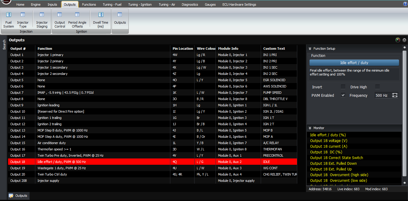
Mazda B engines as in the MX5 / Miata we generally use about 500 Hz
You can check that it’s connected electrically by looking in the diagnostic screen for the voltage and current for that output. When the output is on (eg if the engine is stopped, or if you set the output to none, inverted) the voltage should be about 0V, because the ECU is pulling that line down. The current should read a positive value, eg 1 – 2 Amps. When the output is off, for example if you set it to none or set the idle duty cycle to zero, the current should be approximately zero and the voltage should show battery voltage, eg 12V.
The next type is the 3-wire. There’s an old style Bosch idle valve with 3 wires, I’m not sure which cars it was used on – and it’s also found on some Subarus and Toyota engines. We’ll discuss the standard connection first of all but there’s an alternative connection I’ve also see which is a bit different.
Instead of the single coil, which pulls to open the valve as on the 2-wire type, the 3-wire idle valve has 2 coils. When one is energised, the opens the valve and allows more air to flow. When the other is energised, it closes the valve and allows less air to flow. If you don’t energeise either coil, for example if you just unplug the motor, it flows about half its maximum amount.
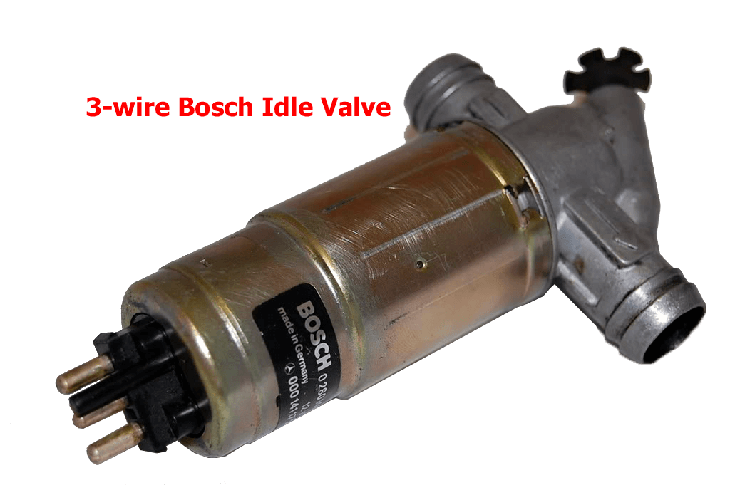
3-wire Bosch Idle Valve
To connect this, the standard way is to connect the middle pin to 12V, and either side to a high current output on the ECU, ie either an injector or an auxiliary output. One output must be configured as Idle effort, PWM, the same as with the 2-wire solenoid. The other must be Idle effort, PWM, but the output should be inverted. Both should have the same PWM frequency, we’ve found 250 Hz works well.

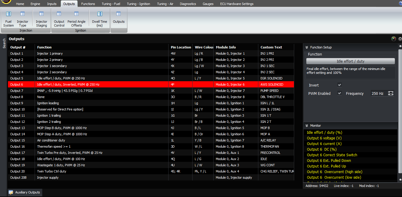
The one which is configured as idle effort must be the one that is pulled low to allow more air into the RPM, ie the one that increases the idle speed.
You can check that the outputs are connected correctly in the same way as with the 2 wire idle valve, except that you have 2 outputs to check instead of just one.
One way I’ve seen these connected differently is that instead of the middle terminal connected to 12V and each outside terminal pulled to 0V in turn, is that the two outside pins are connected to 0V and 12V, and the middle terminal connects to the ECU. In this case, you should use an auxiliary output to drive the idle motor, and enable the “drive high”. Normally the factory wiring would be so that pulling the pin to ground increases the idle speed, but if not, then just select “invert” on that output so it becomes idle effort, invert instead of just idle effort. In this case the PWM frequency should remain the same as with the conventional connection, as I mentioned earlier so far 250 Hz has worked well with these. So far the only time I’ve seen this is with the cable throttle series 2 Lotus Elise and Exige with the 2ZZGE engine. Interestingly, when the 2ZZ engine is used in the Celica, it’s connected normally with 12V on the middle pin and the two other terminals going to the ECU.

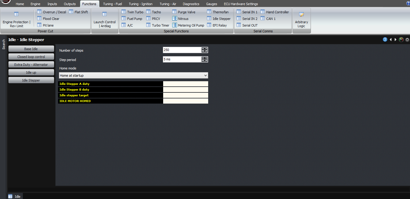
The next type is the 4 wire stepper motor. So far I’ve only seen these on GM engines, but possibly for that reason they seem to be popular in aftermarket installations as well. These stepper motors have 250 steps, and the step period they need is 5ms, so these both need to be set in the idle stepper configuration.
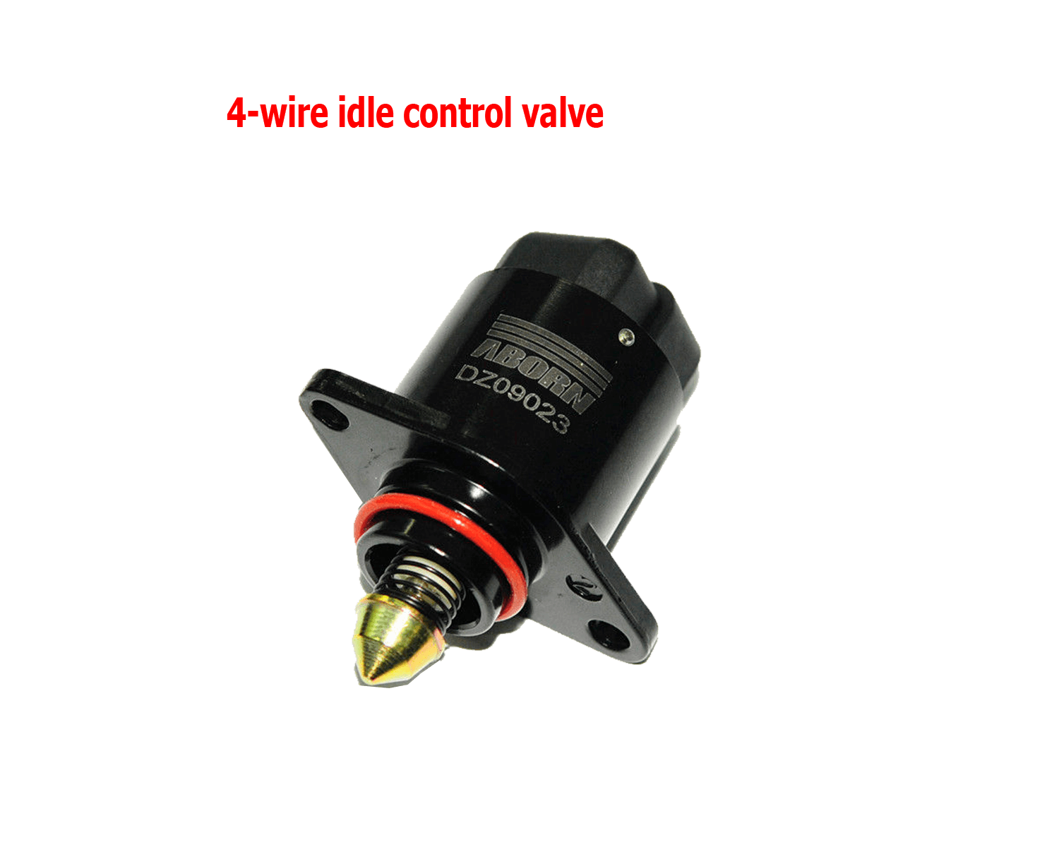
4-wire Idle Control Valve
The 4 wires on the stepper motor connect to two coils internally. Usually the pins are labelled as letters with A B C D, and A and B are one coil, and C and D are the other coil.
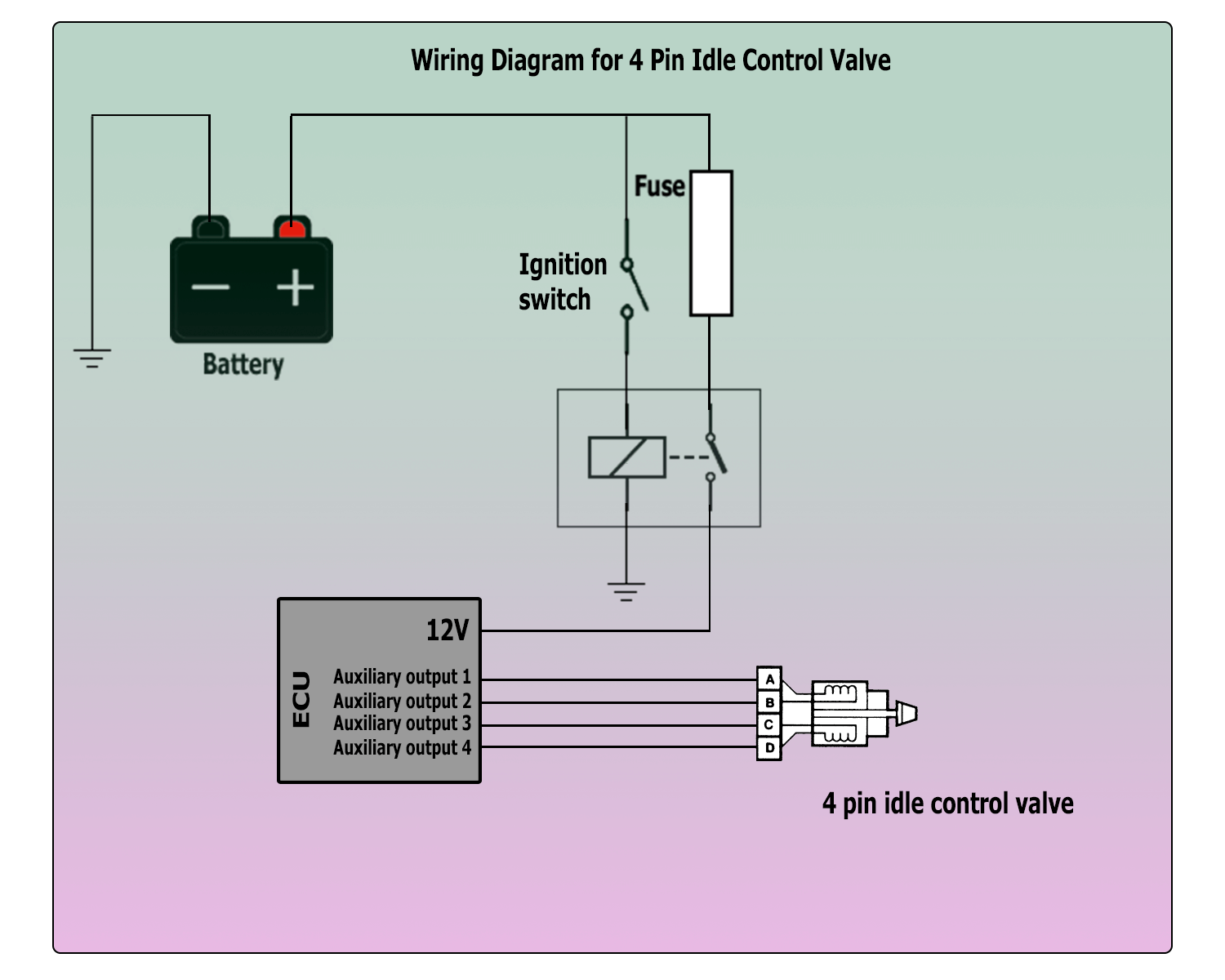
Each coil needs to be driven high at one end, and low at the other.
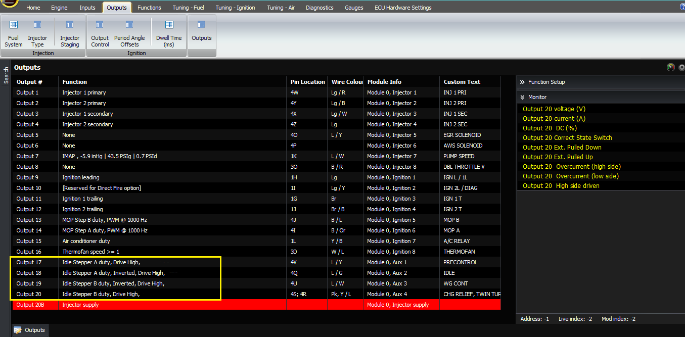
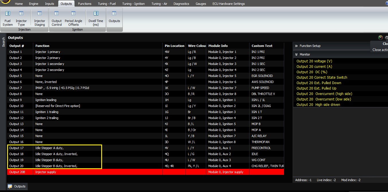
Therefore, to drive one of these motors, you need to use auxiliary outputs (not injector or ignition outputs), and they must be configured as drive high. Here are the settings that are required:
| Idle motor pin |
ECU function |
| A |
Stepper A duty cycle |
|
B |
Stepper A duty cycle inverted |
| C |
Stepper B duty cycle inverted |
| D |
Stepper B duty cycle |
To check that the ECU is driving the outputs correct, set the outputs as follows and check the voltage shown in the software:
| Idle motor pin |
ECU function |
Indicated voltage in software |
| A |
None |
12V |
| B |
None inverted |
0V (current should be > 0) |
| C |
None inverted |
0V (current should be > 0) |
| D |
None |
12V |
And now invert the outputs and check that they work in the opposite phase:
| Idle motor pin |
ECU function |
Indicated voltage in software |
| A |
None inverted |
0V (current should be > 0) |
| B |
None |
12V |
| C |
None |
12V |
| D |
None inverted |
0V (current should be > 0) |
If the current shows as zero on the output which is at 0V, that means that either there’s a bad connection between the ECU and the motor on that pin, or the other pin on the same coil. If the voltage does not switch between 0V and 12V correctly, but the ECU setting is correct (ie “drive high” is enabled), then either there’s a short circuit or the ECU output has been damaged.
If your 4-wire stepper motor has pins labelled differently, then you can work out which pins are joined internally with a multimeter. However the direction could still be reversed, ie a higher idle effort could result in less airflow and lower RPM. If this happens, then swap around outputs C and D, ie C becomes Stepper B and D becomes Stepper B inverted.
At the moment, we recommend using the home mode as “home at startup” which ensures that the stepper starts from the same position each time you start the engine, which is necessary for consistency.
The last type of idle valve we will discuss is the 6-wire stepper motor. These are similar to the 4-wire motors except that each coil is actually 2 coils with a centretap, which is connected to 12V. Normally it will be connected as a 6 pin plug with 2 rows of 3 pins, and the middle pin on each row needs to be connected to a ignition switched 12V source.

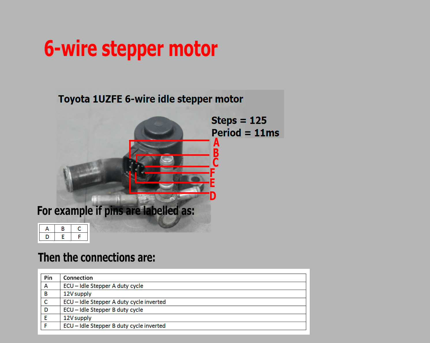
Each of the outside 4 pins then needs to connect to an output on the ECU. It’s acceptable to use unused ignition outputs for this use because the stepper motor draws very little current.
The outputs then need to be configured the same as with a 4 wire stepper, but without the drive high function enabled. For example if the pins are labelled as:
| A |
B |
C |
| D |
E |
F |
Then the connections are:
| Pin |
Connection |
| A |
ECU – Idle Stepper A duty cycle |
| B |
12V supply |
| C |
ECU – Idle Stepper A duty cycle inverted |
| D |
ECU – Idle Stepper B duty cycle |
| E |
12V supply |
| F |
ECU – Idle Stepper B duty cycle inverted |
Again, the number of steps and step period must be configured. The Mitsubishi steppers we’ve tested have 120 steps whereas the Toyota have 125. Both are happy with 10ms steps. Again we recommend using the “home at startup” mode.
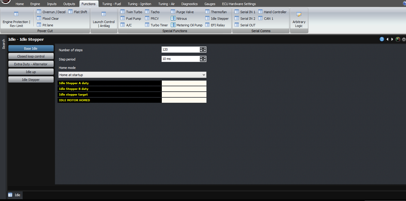
Mitsubishi
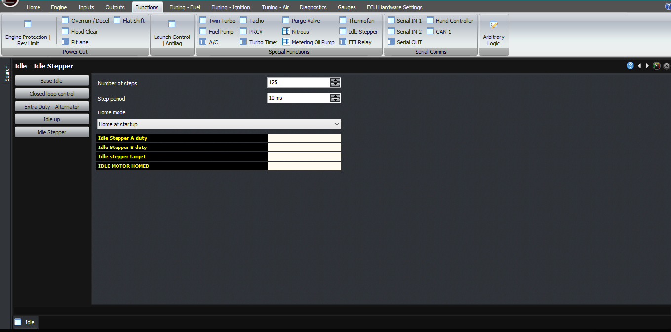
Toyota
Just as with the 4 wire stepper motor, depending on exactly how your stepper is wired, this above configuration can result in the stepper driving the wrong way, ie a higher idle effort corresponding to a lower RPM. To rectify this, simply swap around the second row, as shown:
| Pin |
Connection |
| A |
ECU – Idle Stepper A duty cycle |
| B |
12V supply |
| C |
ECU – Idle Stepper A duty cycle inverted |
| D |
ECU – Idle Stepper B duty cycle inverted |
| E |
12V supply |
| F |
ECU – Idle Stepper B duty cycle |
To test the outputs are connected correctly, again you can select each output to be “none” and verify first that they all show 12V. As each one is “inverted”, the output voltage should go to zero volts as the ECU pulls it to ground, and you should see a small amount of current at that output also. If the voltage doesn’t pull to 0V and stays at 12V, that means that the output of the ECU has been damaged. If the voltage isn’t at 12V in the first place, or the current stays at 0 even when the output is turned on, it means that the load isn’t connected. Eg there’s no 12V supply to the stepper motor, or there’s no (or a bad) connection between the stepper motor and the ECU, or the stepper motor coil is open circuit (which you can check with a multimeter).
A final word about the meanings of some of the live variables on the stepper motor setup page in the software. The Stepper A and Stepper B motor duty cycles will either be 0% or 100% depending on whether they are being pulled low or not at the time. They will go between 0% and 100% in a sequence, which will be too fast to log but you can see it on the built-in scope or a real scope. So seeing them skip between 0% and 100% is normal.
The ECU calculates idle effort as if it were a duty cycle, from 0 – 100%. So for a stepper motor, the ECU takes this percentage and multiplies it by the number of steps, to arrive at the target step which the ECU is aiming for. This is shown here as the target stepper position. The final flag is idle motor homed, which becomes true after power-up and the motor has been opened all the way to make it easy to start the engine.
We will be doing other articles and videos about setting up the idle parameters.
Thank you and happy learning!
©2018 Adaptronic