Thermofan Control on the Modular ECUs

In this article we’ll discuss the thermofan control on the Modular ECUs.
You might be already thinking, why do we need a special control mode for the thermofan, can’t we just trigger an output based on coolant temperature? Yes you can, but to control a thermofan nicely, there’s a bit more to it than that. That’s the way that we used to do it on the Select ECUs, but it causes some complications, namely:
- You also want the thermofans to come on when the air conditioner comes on, to draw air through the condenser
- You want the thermofan to come ON by default if there’s no sensor connected or a sensor fault, which if you use a generic output based on coolant temperature, you can’t do
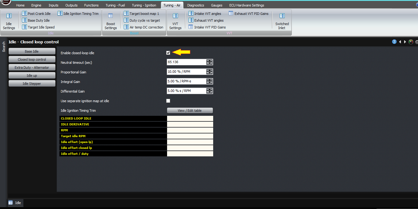
- You want to bump up the idle effort when the thermofan switches on, especially with little engines
- Ideally, you would want to bump up the idle effort slightly BEFORE turning on the thermofan, as we do with the air conditioner, to avoid a dip in the idle speed just after the fan or fans turn on
With all these considerations together, we decided to make the thermofan a dedicated output type on the Modular ECU rather than have people implement it with a threshold based on coolant temperature with a bunch of external logic to make it behave really nicely.
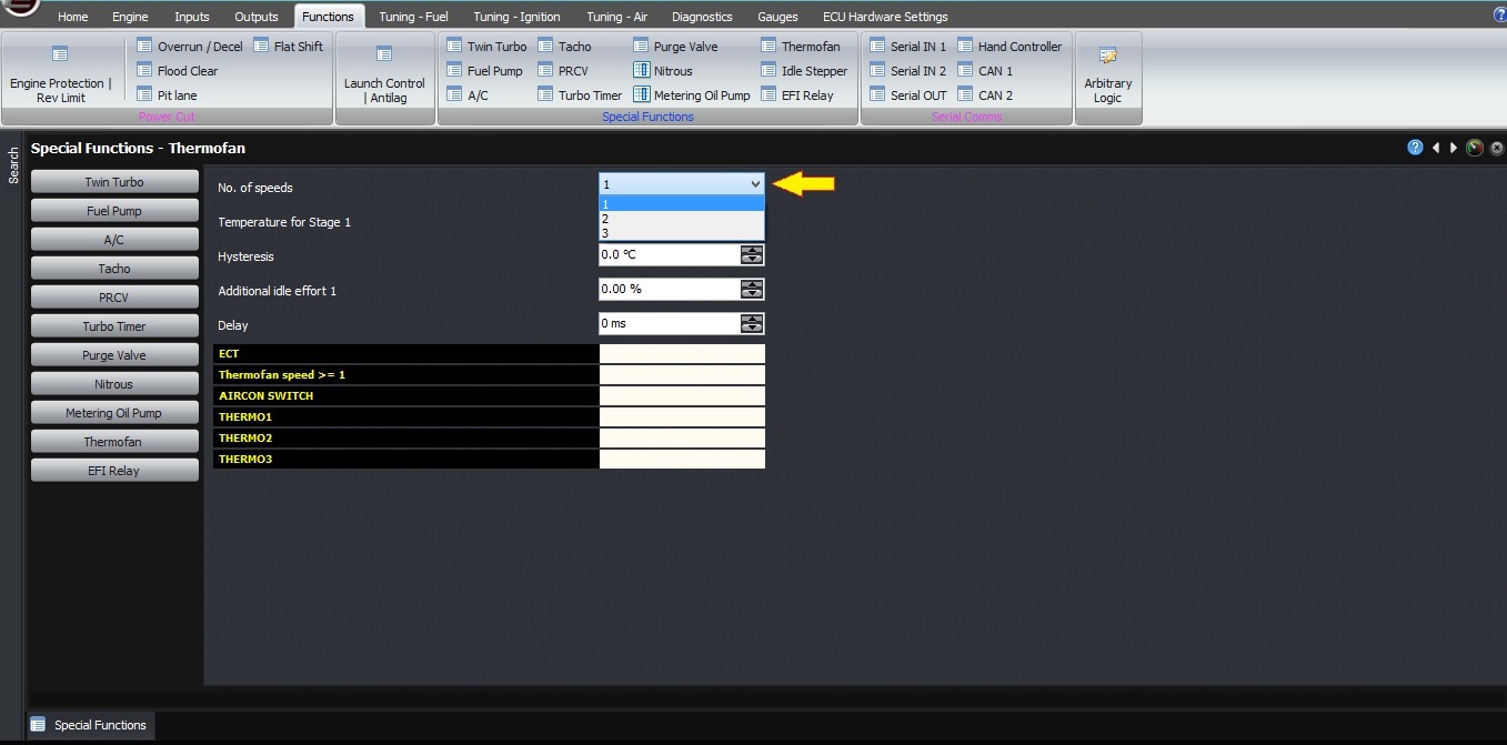
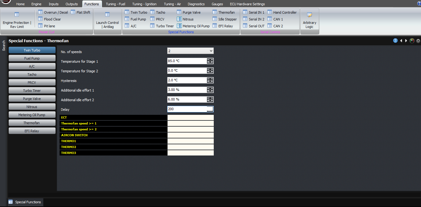
Firstly, let’s look at the different settings available, and these are available in the functions -> thermofan page in the software.
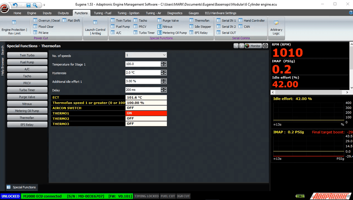
The first is the number of thermofan stages. This can be a number from 1 to 3, and represents the number of different speeds or stages for the fans. For example:
| 1 fan |
1 stage |
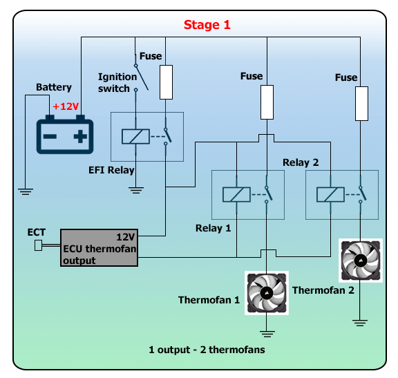
| 2 fans, wired to come on at the same time (single ECU output) |
1 stage |
| 2 fans, independently controlled (2 ECU outputs) |
2 stages |
| 2 fans, able to run in parallel or series or just 1 fan, high / low speed fans etc (3 ECU outputs) |
3 stages |
Thermofan number of stages


A separate output pin on the ECU is required for each stage that you are going to run.
The next setting is the temperate for each stage to be activated. For example if you have 2 stages, then you have 2 activation temperatures. When the coolant temperature goes above the first stage temperature, the first stage will activate. When the coolant temperature goes above the second stage temperature, the second stage will activate.

The next setting is the hysteresis, which is the temperature drop below the activation temperature to turn off the fan. As an example, if you set the temperature to 2 degrees and the activation temperature is 100 degrees, then the coolant temperature will need to go above 100 degrees for the fan to turn on, and it will turn off when the temperature goes below 98.
The next settings are the additional idle effort (percentage) to be applied when each stage is active. For example if you enter 3% here, the ECU will automatically add 3% to the idle duty cycle to help stabilise the idle speed with the additional electrical load from the fan.
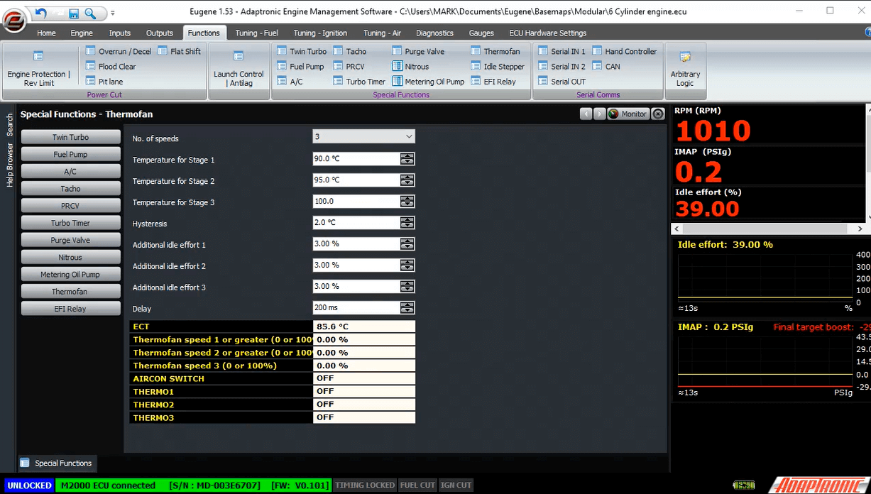
The final setting is the delay. When the coolant temperature exceeds the threshold, the ECU first applies the additional idle effort. After the delay time, the ECU then turns on the thermofan output. This helps reduce or eliminate the idle dip when the fan is turned on.
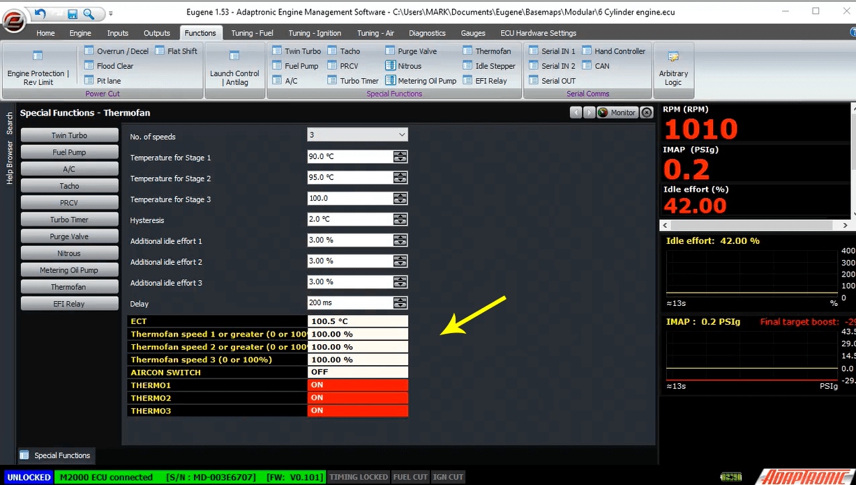
In addition to this logic, the fans are always run at full speed if there’s a coolant temperature sensor failure, or if the air conditioner is active.
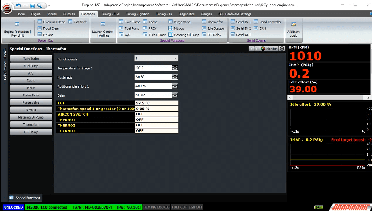
You can see in the software the current state of the thermofan stages and the current temperature.
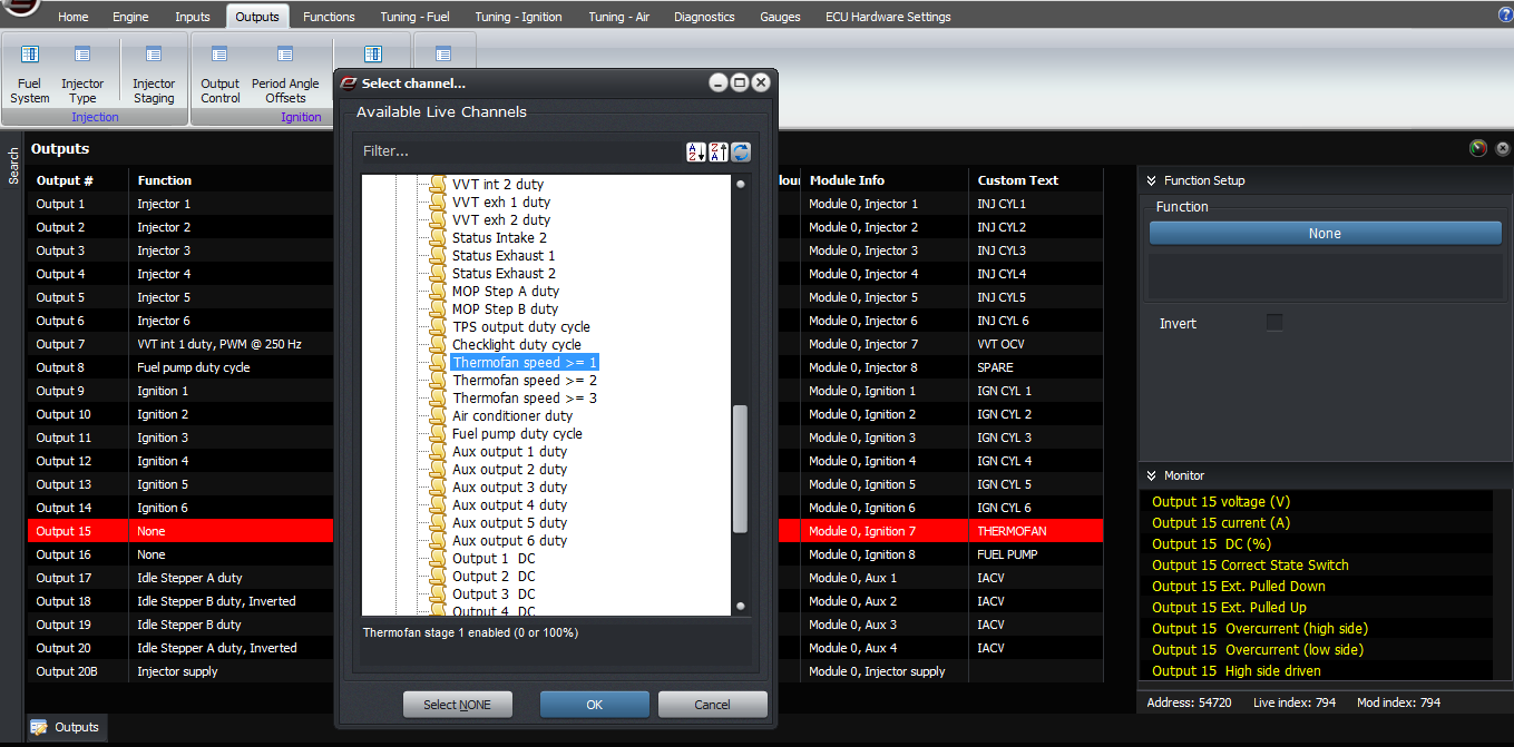
In terms of outputs, you need to connect the relays so that each stage output will drive the fans correctly. The ECU will drive an output low for each stage, and lower. For example if you have selected a 2 stage thermofan configuration, and the ECU is trying to run the thermofans at stage 2, then both outputs 1 and 2 will be on at the same time.
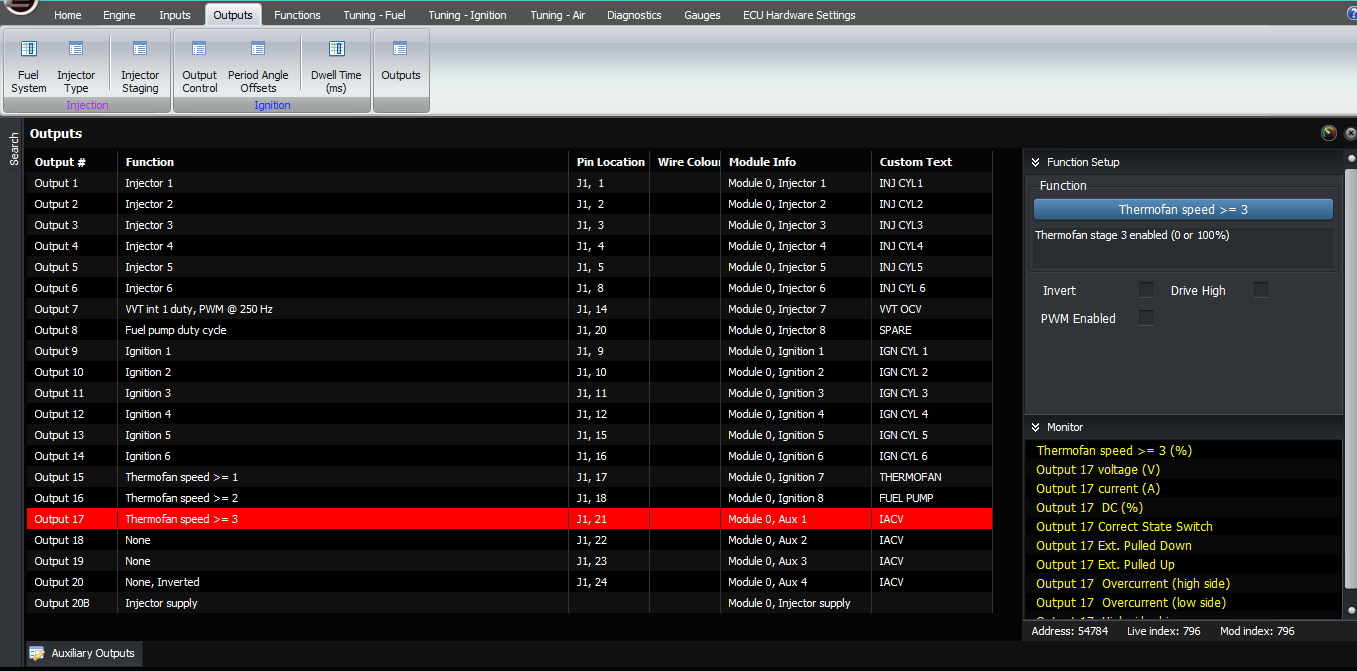
The outputs are configured in the usual way, select a free output, select the category as “outputs” and select “Thermofan speed 1 or greater” for the first stage output. The second fan output needs to be “Thermofan speed 2 or greater”
Once you have it all working, you should set the additional idle effort as follows. Firstly, ensure that your closed loop idle is working correctly. Then, watch the idle effort before the fan is turned on (ie thermofan stage = 0). Then when the engine heats up and the fan is turned on, watch what happens to the idle effort. This new value minus the old value with the fan off is what you should enter in the additional idle effort for thermofan 1 setting. This can also be applied to the higher stages. If the engine doesn’t get hot enough to trigger the thermofan at idle, or you’re impatient like me, you can artificially change the thermofan activation temperature for this test.
Once you’re happy with the extra idle effort, you can adjust the delay to give the smoothest transition of the fan turning on. Generally the delay should be fairly short, eg 200 ms. If the delay is much longer, the closed loop idle control will start to correct for the extra effort when there’s no corresponding load and the dip will become worse and with a shorter delay. But the delay must be long enough for the engine to react, or there is no benefit.
There’s not a lot to troubleshoot with the thermofan that isn’t obvious, but the only thing I’d suggest is that if you have a problem where the fan or fans seem to be coming on all the time, check that you have selected the correct number of stages. If you have selected 2 stages when your car is only set up for a single stage, and the second stage temperature is zero, it means the ECU will see that the engine is always hot (so long as the coolant temperature is above zero, because that’s what you’ve set the high speed fan temperature to), so that’s more than likely the problem in this case.
Wrong setup because temperature 2 is set to zero degrees
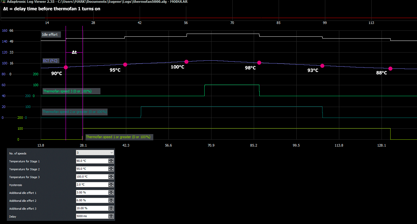
Graph of themofan speed 1 output,
thermofan speed 2 output, thermofan speed 3 output, idle
effort and coolant temp. As coolant temp is ramped up
thermofans switched on but with time delay due to the delay
set in the software and as the coolant temp ramped down
thermofans switched off at certain temperature considering the
set hysteresis.
©2018 Adaptronic