Engine Protection Functions on Modular ECUs

One of the nice things about having a programmable engine management system with multiple sensors connected is that you can program in functions to help save the engine from damages due to mechanical problems or operator error. So in this article we’ll discuss the various protections offered and how to configure them. I’m also going to share a couple of anecdotes at the end to help broaden your system level understanding, so this is a mixed technical / philosophical article.
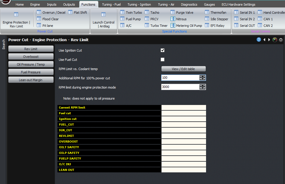
All the engine protection functions are found in the Functions -> Engine Protection / Rev limit tab in the ribbon in Eugene.
The first, and most basic, is a rev limiter. This is grouped with the engine protection functions because that is its function; it’s there to protect the engine from damage from a lead-footed operator, and in one case I know of, it saved an engine whose inlet manifold cracked during a crash (downstream of the throttle body).
On the Modular ECUs, the rev limit is a 2D table against coolant temperature. This is the RPM at which the limiter will start to engage. Another setting specifies the additional RPM to go into a complete cut. This allows the engine not to have rapid torque reversals which can cause damage. You can also specify the method for cutting the power; fuel, ignition or both – and also closing the throttle on an electronic throttle installation. We give the tuner the option because different tuners have their own opinions on which is safer. What I will say is that due to the fuel film phenomenon, performing a fuel cut on a high X engine means that you can end up with an actual lean fire rather than a misfire, which can cause damage. I’ve heard of the factory overboost cut on the RX7 cutting fuel on one of the rotors and cause a lean detonation event; they’d probably be better off letting the engine overboost, rotaries don’t like to rattle. So on rotaries we definitely recommend using ignition cut rather than fuel cut.
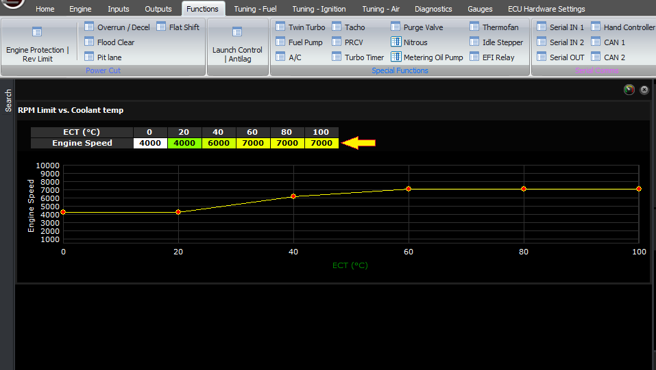
2D revlimit table
In the general case, performing an ignition cut rather than a fuel cut means that you have unburnt fuel going through the engine, which means that it could combust in the exhaust or also damage or reduce the life of the catalytic converter on a street car. So this is probably why most OEMs use fuel cut rather than ignition cut for engine protection. Doing both doesn’t solve the problem, it just gives you the worst of both worlds.
Back to the topic of rev limit, if we set the rev limit to 8000 RPM at the current temperature, and the additional amount for full cut to 200 RPM, that means that at 8000 RPM we will have no cut at all. At 8002 RPM we will have 1% ignition or fuel cut, and at 8004 RPM we will have 2%. Finally at 8200 RPM we will have complete ignition or fuel cut.
Revlimit is set to 8000
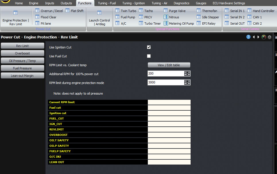
Additional RPM is set to 200
A second setting on the main engine protection page is the RPM at which the engine will be limited in the event of another protection event. This is to allow the engine to still be driven in a way that wouldn’t cause significant harm to the engine, so it can get back to the pits, you can check for leaks, put the car on a trailer and so on.
Also on this main page you can see if any of the protection functions are currently active, and the current rev limit RPM.
Overboost is a fairly common protection strategy on most ECUs. On the Modular ECU, there are two thresholds; one is the instantaneous MAP, if you go above this then the protection is triggered immediately. The other is a one-second value, where the MAP has to exceed this for 1 second to trigger the protection. This allows for short term spikes.
On a dual-bank engine, if EITHER of the MAP values (that is, IMAP or IMAP2) exceed the threshold, the protection will be triggered.
You can also select whether the overboost protection is an actual MAP value, or a pressure higher than the target MAP on a turbocharged engine. For example, if the maximum the engine can handle is 2 bar of boost, then you would set the “overboost selection” as “MAP value” and enter 300 kPaA or 27 PSIg. If you want it to go into overboost protection when the boost is 5 PSI above the target, then set the “overboost selection” as “boost above target”, and enter the pressure as 5 PSId.
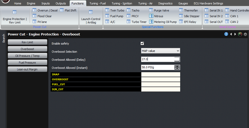
Overboost delay is set to 27PSIg
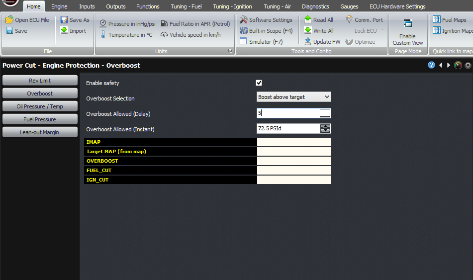
Overboost delay is set to 5PSId
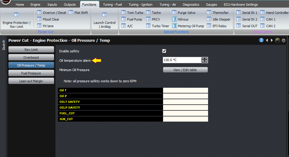
The other engine protections available will depend on the sensors installed on the engine. For example if you haven’t configured oil temperature or pressure sensors, then there will be no oil pressure / temperature option in the menu. So the first step is to set up any inputs required, but you would have already done that when the sensor was installed.
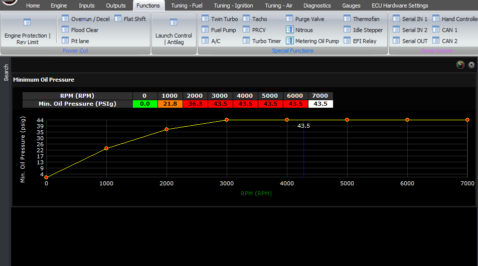
If you have an oil temperature or an oil pressure sensor, the oil safety page will be visible. Oil temperature is a fixed threshold – above this the protection RPM limit will be applied. Minimum oil pressure is a table against RPM. If the oil pressure drops below this value, the protection will be triggered. The oil pressure protection however triggers all the way down to zero RPM, unlike oil temperature which only has a function above the minimum protection RPM. This is so that you can make the engine shut down in the event of an oil pressurization failure, by setting the table appropriately. Also you can prevent this behavior by just putting zero in the minimum oil pressure below the RPM where you care about it.
Fuel pressure is the next safety we will consider. As you know the ECU can measure the fuel pressure and use this as part of the injector model, so a slight drop in fuel pressure should not be the end of the world.

The nominal fuel pressure is shown in this page, but this is the same setting as the nominal fuel pressure in the injector configuration page, so be careful in adjusting this value. The other two settings are the amount the pressure is allowed to drop below this value (which is a differential pressure), and the duration of how long the fuel pressure must be low before it will trigger the engine protection function.
Note that if you have selected “manifold referenced” as the regulator type in Outputs -> Fuel System, then the ECU will calculate the differential fuel pressure from the measured fuel pressure, the MAP and the barometric pressure. It is this value which will be compared to the nominal fuel pressure to determine if there has been a drop in fuel pressure.
If you have selected “Fixed pressure regulator”, then the nominal fuel pressure is considered to be a gauge pressure (rather than differential), and if the measured pressure drops below this pressure setting by more than the “Max fuel pressure drop”, for the “duration fuel pressure drop” then the safety will be triggered. So this system accommodates both manifold referenced regulators, and fixed pressure regulators. It does not accommodate rising rate regulators (ie, where the fuel pressure increases faster than the MAP when on boost).
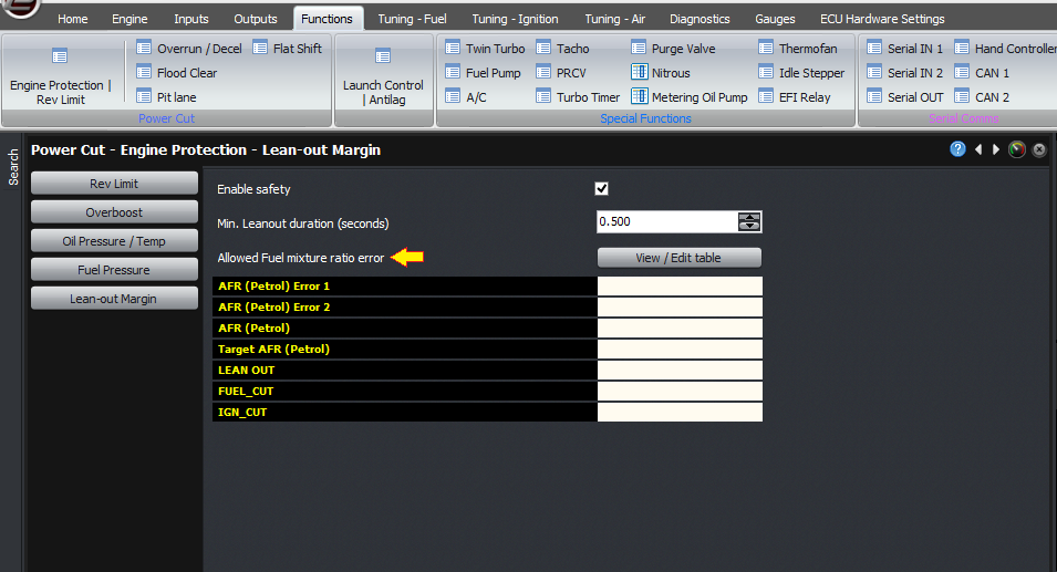
The final safety is leanout margin. The first setting is the duration required. Although most oxygen sensors are quite slow to respond, some such as the Innovate are very fast, and similar to the fuel pressure minimum time setting, the leanout protection function allows a leanout for a very short duration which you can specify here.
The next setting is the allowable lambda mixture error, as a function of RPM and load. This value is the amount of error allowed between the measured lambda and the target lambda. For example, 0.1 means that if your target is 0.82, the ECU will go into protection if the measured lambda remains leaner than 0.92.
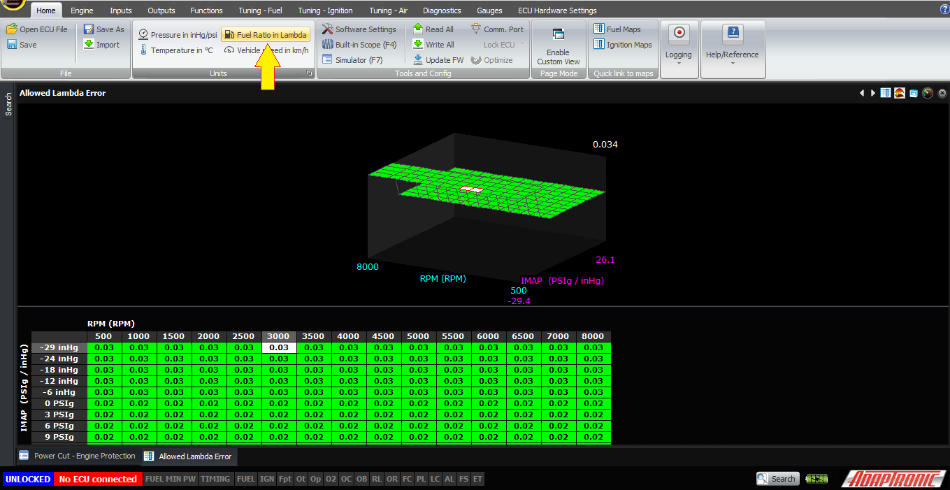
This is configurable against RPM and load because often we really care about this at WOT, so you can specify higher tolerances in the other parts of the map.
Note that if you are displaying in petrol / gasoline AFR instead of lambda, these will show as AFR values instead. Eg if your target is 12:1 and you put 1 in the table, it will go into protection if you remain leaner than 13:1.

Of course this all relies on having good sensors for these inputs. One thing I will say is that we regularly get approached by sensor manufacturers in China trying to sell us their pressure sensors. So far we haven’t taken any of them all that seriously; the first one I told them what we wanted, which was a 1/8″ NPT with 0-150 PSIg being 0.5 – 4.5V, and I wanted a connector for it. The sample they send was a 1/4″ NPT, and although it said 0-150 PSIg on the side, the voltage it measured was not consistent with this scaling. The connector they sent was the male, ie the side already on the sensor, so I don’t know what they were thinking I was going to do with the connector. I’m sure there are some good Chinese sensor suppliers but I’m not going to go through ten like this to try to find them. Something a bit more worrying was I was helping a tuner look at a car which had a fuel pressure sensor on it, and I noticed on the ECU data that the sensor was not reading correctly. He went to check the connection on the sensor, and found fuel in the “connector” end of the sensor. Ie it had an internal leak. Needless to say I’m not a big fan of fuel leaks in the engine bay.
Why do I bring this up? Well really only to say that if you’re worried about the cost of sensors and find the cheapest ones on eBay, then I think it might be a false economy, especially if your car burns to the ground because of a fuel leak. I can think of one customer of ours who lost an engine due to fuel starvation (surge, due to poor surge tank arrangement); he wasn’t running a fuel pressure sensor, but he was running a wideband and disabled the leanout protection because it kept false triggering when driving on the street, although it never false triggered on the dyno. Looking back now, we can say it probably was not false triggering on the street, since it leaned out and cost an engine on the track.
The final anecdote I’m going to share is Aeroperu 603. This flight was a Boeing 757 which took off from Lima on a moonless night, flying out west over the Pacific. After take-off, the pilots both noticed their altimeters were still reading zero, as though they were still on the ground. After a certain amount of time they started to get other warnings, some of which were contradictory such as an overspeed warning and a stall warning at the same time (without being in a very steep climb). As there was no moon, no landmarks they had no visual reference and had no way to judge their actual height or speed. They were in radio contact with air traffic control at Lima, who could report their ground speed by watching their position on the radar, but the altitude shown to the air traffic controller actually came from the altimeter on the plane. At one point the altimeter started to report the plane being at 10 000 feet, when it was actually much lower. The pilots were told the altitude of 10 000 feet, which agreed with the altimeter in the cockpit (because both were actually reading incorrect data from the same sensor), so they thought they could trust it. They were wrong, and ended up crashing into the ocean, killing everyone on board.

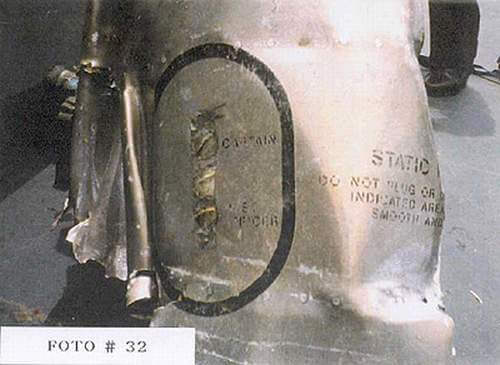
Piece of wreckage showing the tape covering the static ports
Why do I bring up this story? Well, it turns out that the maintenance error was a very simple one; which is that the altimeter in the plane works by measuring the barometric pressure with ports to the outside called “static ports”. “Static” meaning they measure the static air pressure, as opposed to the dynamic pressure which presses on the front of the plane as it travels forward through the air. The difference between the dynamic pressure, measured using pitot tubes, and the static pressure, measured with the static ports, gives the airspeed, and the static pressure gives the altitude. While the plane was being washed, the cleaners taped up the static ports so they wouldn’t get high pressure water into the ports and potentially damage the sensor, and they forgot to remove the tape. The normal supervisor who was supposed to check it was not on that night, the relief supervisor didn’t check it, and neither pilot nor co-pilot saw it during their preflight visual inspection.
So in one sense, a single sensor caused many problems and eventually the loss of the plane and all aboard it. The more complex the system becomes, the more points of failure you create. As an example, to have the fuel sensor as part of the tuning algorithm means that a failure of that sensor could throw out the tune. If the sensor is disconnected entirely, the ECU can default to a safe value of course but if it’s a dodgey sensor whose output drifts over time then you could have a real problem. On a car with flex fuel and many other sensors, a failure of any one of them could lead to an incorrect amount of fuel being delivered. One race car builder I know say that he is all in favour of installing and monitoring the sensors, but he doesn’t even want an ECU safety function to cut power to the engine; he believes the driver should be in complete control. He doesn’t even run overboost or rev limits on his cars because he’s confident enough in his mechanical sympathy to get out of it if there’s a problem. Or, as sometimes happens, he’ll keep driving through it, knowing he’s potentially destroying the engine, because that’s what race car drivers do. But his choice to do this comes from the fact that sensors are sometimes going to fail; and he would rather the driver make the decision as to whether oil pressure is actually low or if the sensor has failed and to keep driving if the driver wants to. I don’t personally agree with this but he does have a point which is that making the system more complex means that you have to be extra careful that you do it right and not do dodgey wiring or things like that which may cause problems later.
Thank you and happy learning!
©2018 Adaptronic