Basic Engine Setup on Modular ECUs

This article describes the basic engine setup of the Modular ECUs.
It’s from this that the ECU works out the majority of what it needs to run the engine, so this has to be right. If it’s not right, you’ll make your life harder and that’s the opposite of what we’re trying to do.
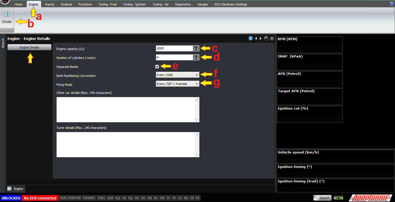
The (a) first tab we’ll look at is the “Engine” one. Select this, (b) and go into the “Details” section. This brings up a window where you can select some really basic information about the engine.
The first is (c) engine capacity, in ccs (cubic centimetres, or mL – or get litres and multiply by 1000, so 2000 for a 2L engine). If you don’t know what this is already but you know the engine type, you can normally find it online somewhere. This is the actual swept volume, we’re not doing any tricks like doubling it for a 2-stroke or anything like that.
The next setting is the (d) number of cylinders or rotors, eg 6 for a JZ or 2 for a 13B. Pretty self explanatory. The only time this would need to change is if you’re trying to duplicate outputs to do something like running 8 methanol injectors per rotor on a 13B, you could in that case tell the ECU that it was a 4 rotor engine but they fire in pairs at the same time, which would have the effect of driving injectors in pairs but give you a separate output per injector, which you need for low impedance injectors.
The (e) next setting is “separate banks”. If this is enabled, then the engine is considered by the ECU to have two halves, and all the fuel calculations including things like predicted MAP, fuel film modelling and so on are done twice. Each bank can have its own intake MAP sensor and/or EMAP sensor and you can run independent closed loop boost control for each. This is particularly useful on dual-plenum engines, because they never balance as well as you’d expect them to. If this mode is enabled, you have the choice to either describe the banks as (f) odd and even, or first half and second half, which allows you to use the “standard” naming convention for the engine. But it also allows you to do the same thing to treat the front and back halves of an inline-6 independently; for example on the GTR each half has its own turbocharger and oxygen sensor, or on a 2-rotor you can do the same thing.
Finally, the (g) firing mode can either be 4-stroke or 2-stroke. A stroke is defined as the distance travelled from top dead centre to bottom dead centre, so 2-stroke means that the engine performs a combustion event every 2 strokes, or 360 degrees. 4-stroke means that the engine performs a combustion event every 4 strokes, or 720 crank degrees. Both configurations still must perform the suck-squeeze-bang-blow sequence because that’s how the Otto and Diesel cycles are defined. Note that this does not directly affect the ignition output sequence, which will be configured later, but it does affect whether the injectors are fired every 360 or 720 crank degrees, and also affects calculations such as the fuel film changes. So on a 2-stroke piston or a rotary engine, select 360° / 2-stroke – otherwise for a 4-stroke piston engine select 720 ° / 4-stroke
The next section we will cover is the outputs, ie what the ECU actually controls, particularly the injector and ignition outputs.

(a) Go to the “outputs” tab, and (b) then select “fuel system” from the injection panel. This is where we enter the basics about the fuel system.
The (c) first setting, manifold referenced or fixed, is whether the fuel pressure has a constant differential pressure, ie the fuel pressure reg is manifold referenced, or if the fuel pressure has a constant gauge pressure, ie no manifold reference. Often this is incorrectly described as dead-head or return style system, but there is nothing stopping you from running a manifold referenced dead-head system or a return style system with no manifold reference. Generally we prefer to see manifold-referenced systems so that the injector behavior is more consistent but the ECU can handle either in the fuel model.

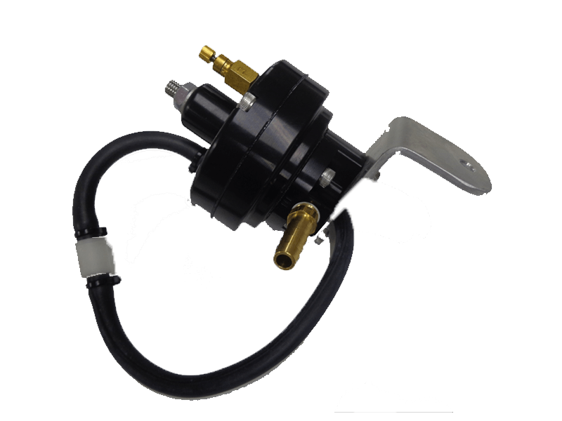
Fixed Pressure Regulator
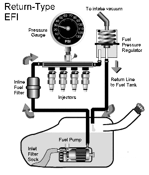
Manifold Referenced
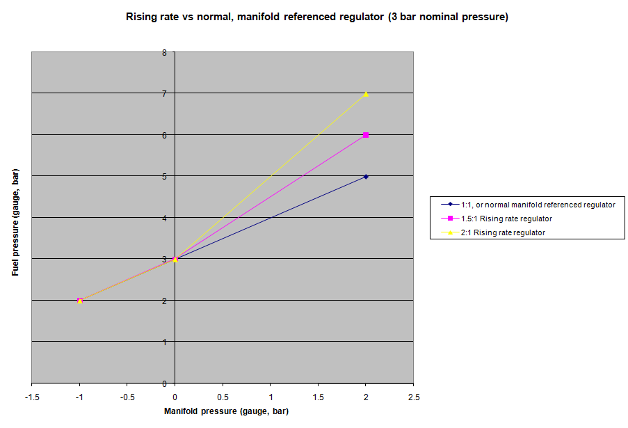
The type that the ECU doesn’t support, unless you have a fuel pressure sensor, is the rising rate fuel pressure regulator; in this pressure regulator the differential fuel pressure increases with manifold pressure. For example for every 10 kPa of manifold pressure increase, the gauge fuel pressure might increase 20 kPa, which means that the differential fuel pressure has increased by 10 kPa instead of being constant. If you have a fuel pressure sensor the ECU can handle this though.
The (d) next setting is the nominal fuel pressure. Normally this should be set to the minimum that you see at the full power condition. If the ECU detects a failure in the fuel pressure sensor, it will reference this value instead. In a manifold-referenced system, this is the differential fuel pressure, as you can see by the units being kPaD (or PSId in Imperial units). In a fixed pressure system, this is the gauge fuel pressure, the units being kPaG or PSIg. A typical fuel pressure is about 3 bar for manifold referenced and 4 bar for fixed fuel pressure.
The next option, (e) fuel pressure modelling, tells the ECU how to work out the fuel pressure; either from a fuel pressure sensor, or from the nominal fuel pressure setting. If there’s a fuel pressure sensor, we would recommend using the sensor.
The next checkbox is to (f) trim for fuel density. Again we would recommend to have this turned ON, because it means that fuel temperature changes will be accounted for in the calculations. The coefficient of expansion of fuel is different between E85 and E0 so this is taken into account also. The fuel temperature can either be taken from a dedicated fuel temperature sensor, or it can be read from the ethanol sensor if equipped (because it tells the ECU temperature and ethanol percentage), or it can be modelled from the engine temperature. The ECU assumes some heat soak and that the fuel temperature will start off at engine temperature but eventually stabilise. If you prefer to model this yourself you can disable this feature and trim it using the post crank enrichment table.
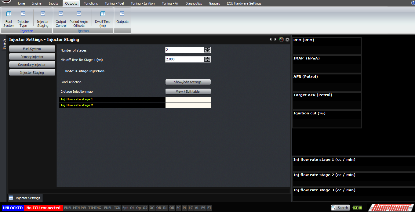
If you now click on the “injector staging” button you can set up the staged injection. If you aren’t running staged injection, just set the number of stages to 1 and that’s all you need to do. Otherwise, set the number of stages you’re using and set the off-time for each stage – we normally recommend 2 ms as enough time for the injector to fully close so that when you open it again it delivers the correct amount of fuel.
Next, in the injection panel select “injector type”. For each stage of injectors you have, you will need to select the injector type from the dropdown list. If your injector isn’t in there, then you will need to select “custom” and enter the dead times and flow rates against fuel pressure (and battery voltage as well for dead time) manually.

Now that we have fully described the fuel system, we need to tell the ECU about the ignition system. The first step is to go to “Output control” in the “Ignition” panel. From there, the first thing is to select the ignition output mode.
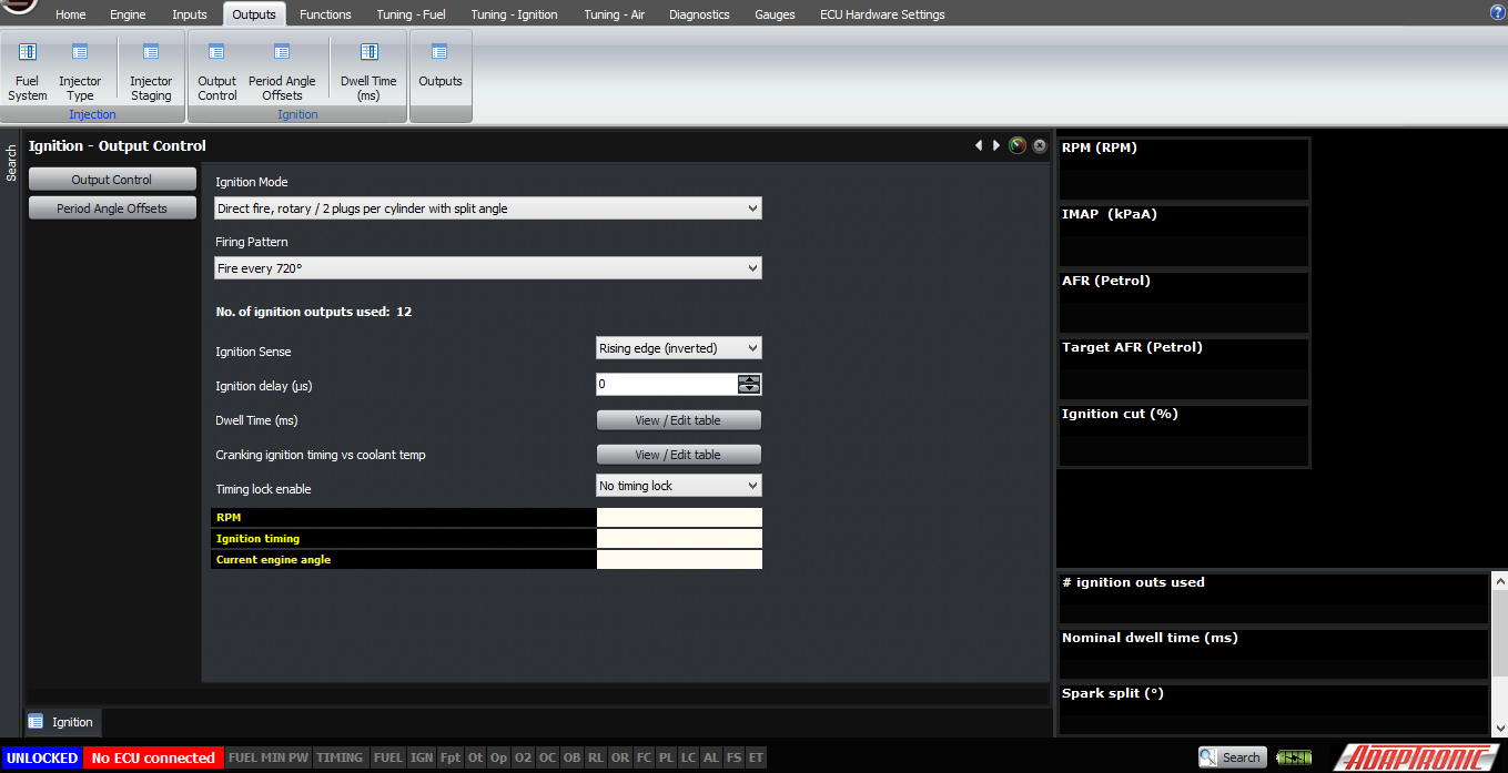
For a rotary, or an engine with two spark plugs per cylinder, there are a few different modes available:
Direct fire, rotary / 2 plugs per cylinder with split angle is the most simple and just uses a single coil per plug. In this mode, you must select the firing pattern as well, which will be 720 degrees on a 4-stroke and 360 degrees on a rotary or a 2-stroke. If you don’t have a cam trigger on a 4-stroke, you will need to fire the ignition every 360 degrees. And a cool feature is the option to fire every 360 degrees until a cam signal is detected where it switches over to 720 degrees.
FD: wasted leading, direct fire trailing – for the factory ignition system on the RX7 FD
FC: wasted leaning, address mode trailing – factory ignition system on the RX7 FC
For a single plug per cylinder, the following modes are available:
Direct fire, single plug per cylinder. In this mode the ECU allocates one ignition output per cylinder. The ignition firing pattern must be set to 720, 360 or 360 then switch to 720 with cam information.
Wasted spark. In this mode, only one output is used for every 2 coils, and the firing pattern needs to be set to every 360 degrees. This works for 4 cylinder, 6 cylinder and 8 cylinder flat plane engines. For 8 cylinder crossplane engines, the cylinder mapping needs to be different so that ignition outputs 1-4 correspond to the 4 separate pairs.
Single distributor. In this mode, only a single output is enabled. The firing pattern is set automatically based on the firing frequency of the engine (720 or 360) and the number of cylinders.
Twin distributor. In this mode, two outputs are used; the first being the one for cylinder 1 and the other for the other distributor. Again the firing pattern is set automatically in this mode.
The next setting to check is the ignition sense. This should normally be “falling edge (normal)”. Very few systems require a rising edge, and if so then you should know about it and have seen the waveform on a scope for yourself. Setting an output to rising edge when it should be falling edge can burn out ignitors and ignition coils.
The dwell time table can now be set, as a function of engine speed and battery voltage.
Lastly, but definitely not least, is the set of period angle offsets. These are found in the “Ignition” panel again. These period angle offsets are the number of degrees after TDC ignition cylinder 1 that each of those cylinders gets its TDC ignition.
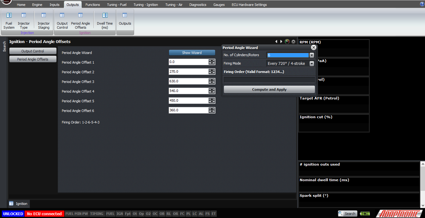
For example, if your firing order is 1-3-4-2 on a 4 stroke piston engine, the firing order angles are:
0, -180, 180, 360
This period angle offset is used for the injection timing as well as ignition.
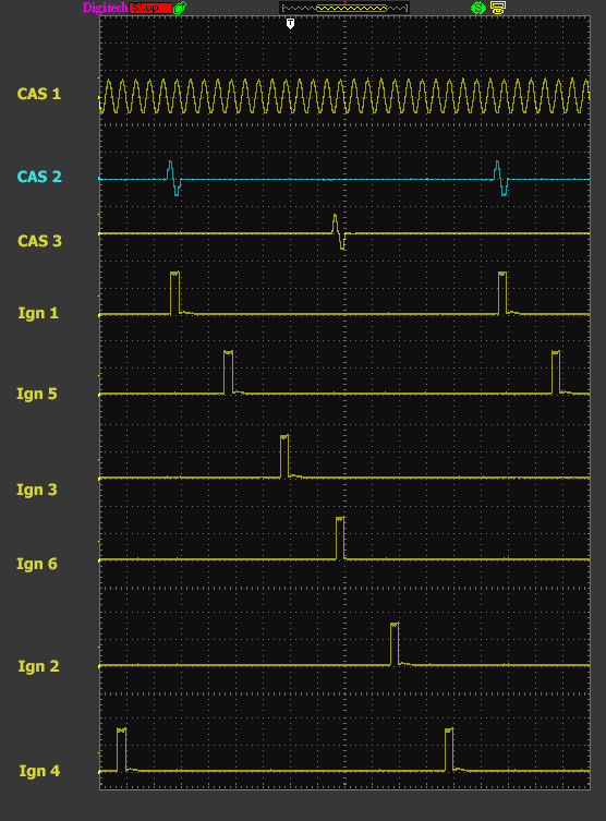
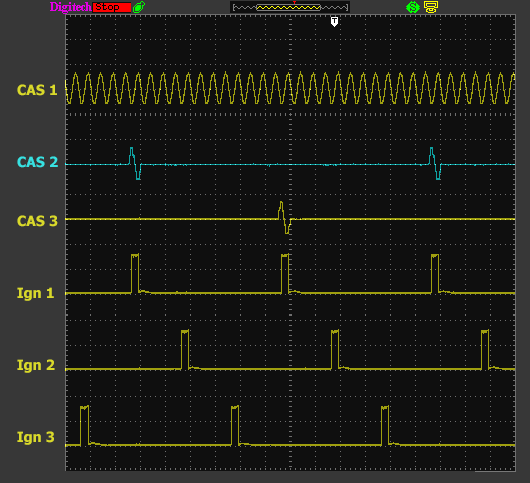
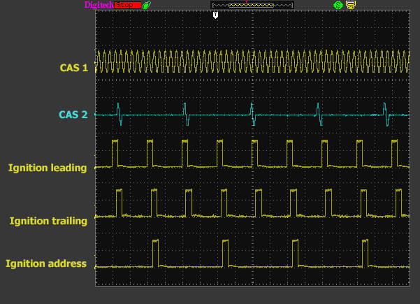
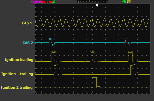
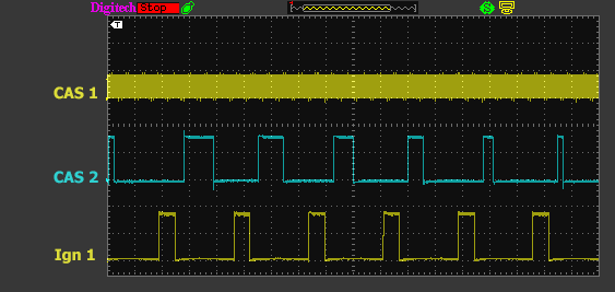
Here are the samples of different ignition output waveforms:

2JZGET_SingleDistributor
2JZGTE_Directfiresingleplug

2JZGTE_DirectRotary
2JZGTE_WastedSpark
FC
FD

Nissan6-WastedSpark
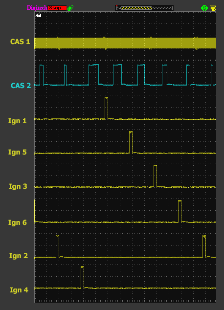
Nissan6-DirectFiresingleplug
Nissan6-SingleDistributor
©2018 Adaptronic