ECU Grounding Tips

There have been many “debates” about the best way to ground ECUs, so the best way to answer this is to go back first to its theory. It is however, complex, with several separate considerations, and when someone see how they all interact they’ll see that there is an optimal solution which is the same for most cases.
First of all we’ll going to discuss the separate problems we’re trying to avoid, and then how to analyse them and optimize the ground layout for each of the problems. The two main problems are ground offsets due to common impedance paths and magnetic field noise.
Ground offsets are often not very well understood, which is a missed opportunity because they are quite simple to visualize if you draw a diagram.
To analyse a system for ground offsets, first draw a diagram of the system. Then remember that every wire has resistance, which means that there will be a voltage drop across the wire, depending on the current flowing through it. Since we’re talking about the context of ECU grounding, we can look at the voltages from the ECU’s perspective and predict what can go wrong due to the voltage drops.
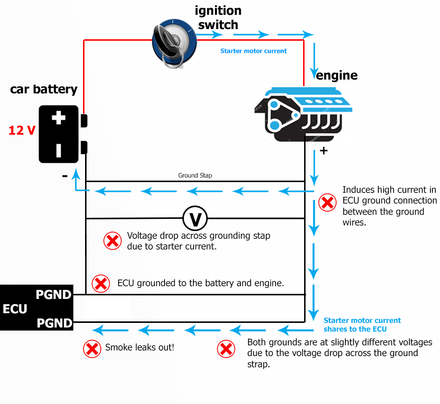
In this first example, the installer has grounded the ECU to the engine and also to the battery. Someone might ask why would anyone do that, but some people do. During cranking, a lot of current flows through the ground strap between the engine and the battery, so there’s a voltage drop between the engine and the battery. This in turn induces current in the ground wires going to the ECU; or in other words, the ECU shares some of the starter motor current. Exactly how much depends on the relative resistances between the ECU grounds and the ground strap; if the ground strap is in good condition then not much; but otherwise people have blown up tracks in the ECU by doing this. So obviously this case is bad!
 This
second example is one of the interview questions we use when
looking for support engineers. It’s actually a mistake made
by Mazda in the factory NA6 MX5 / Miata loom; they fixed it on
the next model (the NA8). The sensor ground is externally
grounded to the engine, as well as to the ECU. The ECU is
grounded to the engine also. We know that as the injector duty
cycle increases, the average ground current of the ECU will also
increase, and therefore so will the voltage drop between the ECU
and the engine. The ECU ground will be sitting at a slightly
higher voltage than the engine ground, so any sensors connected
to the engine ground instead of to sensor ground on the ECU,
will read a lower voltage. In the case of coolant temperature,
it means that as injector duty cycle increases, the voltage seen
by the ECU on the coolant temperature input reduces and the ECU
believes the engine is at a higher temperature. This is fairly
easy to spot in logs; you can look for noise on inputs such as
coolant temperature, throttle position etc, but it causes
problems for obvious reasons.
This
second example is one of the interview questions we use when
looking for support engineers. It’s actually a mistake made
by Mazda in the factory NA6 MX5 / Miata loom; they fixed it on
the next model (the NA8). The sensor ground is externally
grounded to the engine, as well as to the ECU. The ECU is
grounded to the engine also. We know that as the injector duty
cycle increases, the average ground current of the ECU will also
increase, and therefore so will the voltage drop between the ECU
and the engine. The ECU ground will be sitting at a slightly
higher voltage than the engine ground, so any sensors connected
to the engine ground instead of to sensor ground on the ECU,
will read a lower voltage. In the case of coolant temperature,
it means that as injector duty cycle increases, the voltage seen
by the ECU on the coolant temperature input reduces and the ECU
believes the engine is at a higher temperature. This is fairly
easy to spot in logs; you can look for noise on inputs such as
coolant temperature, throttle position etc, but it causes
problems for obvious reasons.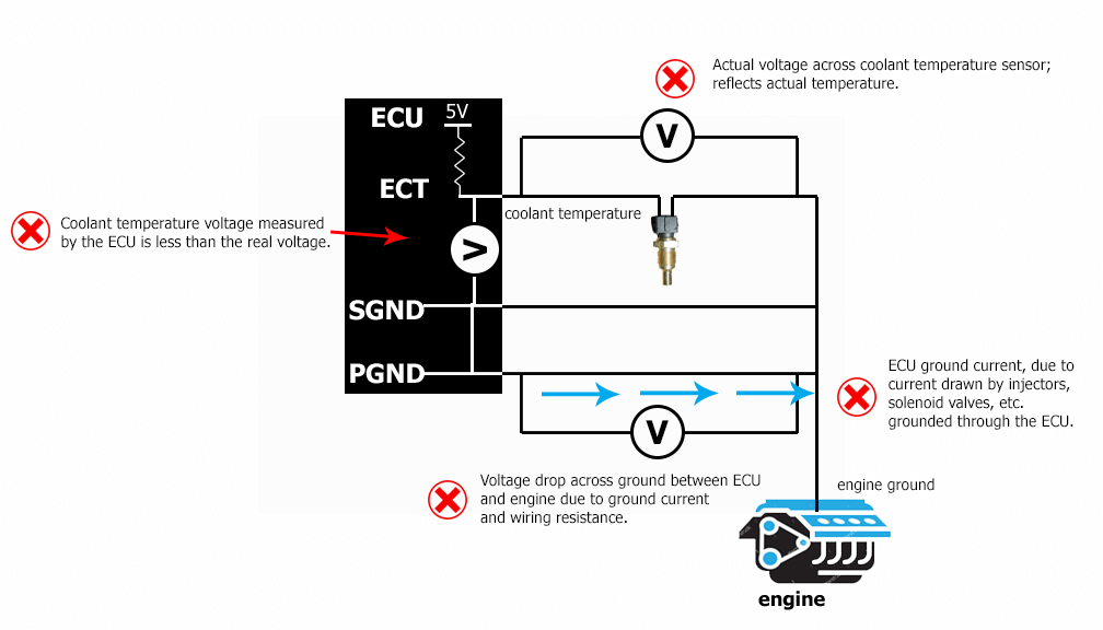
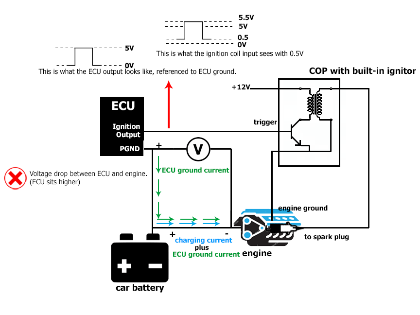
In this last example, the car has coil-on-plug ignition. The coils are grounded to the engine, and the ECU is grounded instead to the battery. As the engine speed increases, the alternator charge current increases and so the voltage drop between the engine and the battery increases also. Let’s assume the grounding to the ECU from the battery is also substandard, which means that as injector duty cycle increases, the voltage drop between the ECU and the battery also increases. We now have a double effect causing the ECU ground to sit higher than the engine ground. The coils however are grounded to the engine, which means that when the ECU is outputting zero Volts on its ignition output, the coil sees a positive voltage (equal to the voltage drop described earlier) on its input. Some coils with built-in ignitors only need 0.7V to trigger, which means that in extreme cases you could even get the coils to trigger by themselves, while the ECU is outputting zero volts on its ignition output. Of course this spark would be at a completely unpredictable engine angle and on a fragile engine like a rotary could destroy it very quickly. This is how important good ground hygiene is!
 In
all of the examples, the problem is common impedance paths. We
have one path (eg a wire) which has multiple things referencing
it (eg injector current feeding through, but offseting the
voltage for the coolant temperature sensor). The way around this
is star earthing. People should pick a single point for
ground, and reference all grounds there. Actually
it doesn’t really matter whether this point is the engine
or the chassis or the battery negative, but there are other
factors which I’ll explain later.
In
all of the examples, the problem is common impedance paths. We
have one path (eg a wire) which has multiple things referencing
it (eg injector current feeding through, but offseting the
voltage for the coolant temperature sensor). The way around this
is star earthing. People should pick a single point for
ground, and reference all grounds there. Actually
it doesn’t really matter whether this point is the engine
or the chassis or the battery negative, but there are other
factors which I’ll explain later.Sensors, if they have the ground isolated from the sensor body (for example TPS, pressure, temperature sensors), they must be grounded to the sensor ground on the ECU, not the engine ground. The reason for this is as given in the second example above; if you ground the sensor to the engine ground, then its output is going to be offset by the ground current times the ground resistance. This is why ECUs have dedicated sensor ground wires.
If the sensor’s ground is not isolated
from the body of the sensor and it has to screw onto the engine,
for example many Nissan cam angle sensors, narrowband oxygen
sensors and many knock sensors, then you don’t have a choice;
you have to choose the star point ground at the engine. Because
the engine is so thick and low resistance, the actual point on
the engine doesn’t matter too much; but often this point is on
the inlet manifold or cylinder head on production cars.
The next issue that we need to discuss is magnetic field noise. This is one of the two forms of electrical interference that can be generated by electrical circuits. This is actually an entire discipline called EMC, or electromagnetic compatibility, and spark ignition engines have their own standard they must comply with (it’s called CISPR12 if you’re curious).
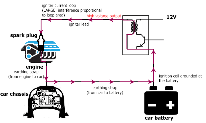
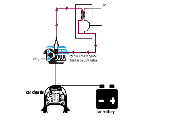
Magnetic fields are created by currents flowing in a loop. We all remember from school that current has to flow in a circuit, but they probably didn’t tell you that currents flowing in a loop create a magnetic field. The higher the current, and the higher the loop area, the greater the magnetic flux. Increasing the number of turns also increases the flux which is why ignition coils, fuel injectors, transformers and so on have many turns of wire. The main consideration we have to worry about with magnetic field noise is high frequency noise; and the noisiest source of magnetic field interference in an ECU system is the high voltage side of the ignition system. If you consider the circuit of a typical direct fire system, the high voltage is generated at the output of the ignition coil. The current travels along the ignition lead (if there is one), down the center electrode of the spark plug, where it jumps the gap via ionized air and down to the ground strap of the spark plug. From there the current flows into the cylinder head or rotor housing, and it has to find its way from there back to the secondary of the ignition coil. On most modern coils this connects through the power ground terminal of the ignition coil. Therefore, to minimize electrical interference, this loop area has to be as small as possible. If you ground the ignition coil to the battery, you have a problem because the high voltage current has to flow out of the head, to the grounding strap to the battery and then back from there to the ignition coil. The loop area is very large compared to if the coil was grounded to the head, and this creates electrical interference. This interference can get into crank angle sensor wiring and cause triggering problems, but more on that later.
Large Loop Area
Small Loop Area
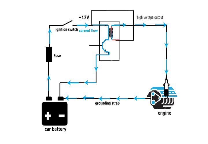
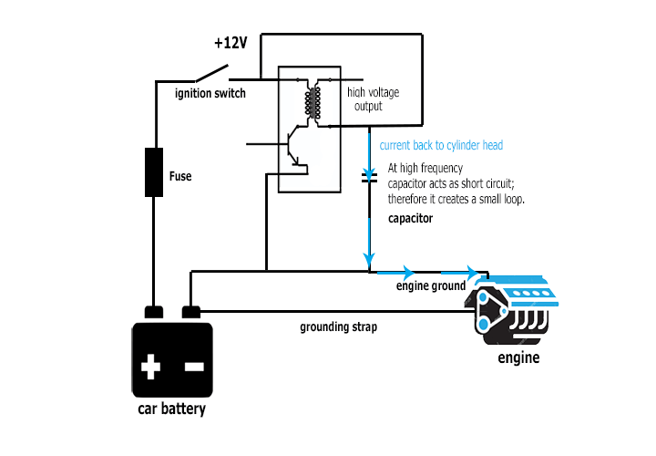
On old style, 2-pin ignition coils, the secondary of the coil is connected not to ground but to the positive 12 Volt supply to the coil. Therefore there needs to be a path from this 12V supply back to the cylinder head. Without any other changes, this would have to go through the battery and then from the battery negative to the engine through the grounding strap. That is a large loop area. So in such systems normally they would have a capacitor that connects between the 12V supply to the coil and ground. The capacitor can be thought of as being a short circuit at high frequencies, so the high frequency current from the ignition system can then bypass the rest of the electrical system on the car and go straight back to the head.
Large Loop Area
Small Loop Area
As mentioned earlier noise getting into crank angle sensor wiring and causing triggering problems. Firstly, this can often be misdiagnosed because it’s a complex interaction. As the load on an engine is increased, the ignition system generates more noise, because it requires a higher voltage to ionize the higher pressure air in the cylinder. This noise can then get into the trigger input. So although it’s a trigger problem, it is load dependent. And although it’s a trigger problem, it’s caused by the ignition system. So the fact that a misfire is load dependent does not rule out a trigger problem, but at the same time changing the ignition system may not fix the problem.
Also, they say that there’s no shortage of advice online but there’s a shortage of good advice. We’ve seen people say that “you should rerun your crank angle sensors with really good shielding and that will help keep out the ignition noise”. If the shield is copper or aluminium, it’s not going to do anything to the magnetic interference because those metals are not magnetic. So although people say to do it, my first recommendation would be to check that the ignition loop current area is as small as you can make it. If we’ll look at any OEM ignition system, we will see that’s exactly what they’ve done.
There are other factors that will influence the amount of magnetic noise that a system generates. Running non-resistor plugs will generate more noise than resistor plugs. Running solid leads will generate more noise than resistor leads. Higher boost / load will generate more noise. Larger gap will generate more noise for the same reason.
Finally, most ECUs allow changes to the amount of filtering and voltage thresholds for the crank and cam sensor inputs, so in many cases you can filter out the noise anyway. In some cases it just won’t be possible though and it depends on signal to noise ratio. This is one reason I really like reluctor sensors over Hall effect; the voltage of the sensor increases with RPM, and generally if there’s going to be a trigger problem it’s going to be when the engine is at mid to high RPM anyway, so the reluctor sensor gives you a much higher signal to noise ratio than Hall effect.
So, now to the punchline. Because we are going to use star earthing, we need to pick a point for it. Because the coils need to be grounded to the engine to keep the loop area small, that means that the star point has to be the engine. This also conveniently works for some sensors whose output is not isolated from the chassis, for example many Nissan cam sensors. And if you look at almost any OEM installation, they ground the ECU to the engine.
Thank you and happy learning!
©2018 Adaptronic