Triggering on Modular ECU

Triggering is one of the most poorly
understood areas of ECU configuration, and it’s arguable the
most important one to get right. It’s certainly the one that
cause a lot of engine damage if it’s not right.
One thing that I always say is to make sure we understand the objective. What problem are we solving? The whole point of triggering is for the ECU to know the current engine angle as accurately as possible, and as quickly as possible from when the engine starts to crank. The more accurate the ECU’s knowledge of the engine angle, the more stable the ignition timing will be and the closer it can run to the ragged edge. The less rotation that the ECU requires from the triggering system before it knows the angle, the faster the engine will fire up from cranking.
The ECU always tracks the engine angle over a 720 degree period; and this is represented as a range from -360 to +360 degrees and then straight to -360 again. Zero degrees is defined as cylinder 1 TDC ignition. For 2-stroke engines, including rotaries, the ECU still calculates the engine over the 720 degree range but the injection and ignition is fired every 360 degrees.
There are several preconfigured triggers for various engines, so if your engine is listed then use it. Start with the base angle of zero degrees, and then fine tune the ignition timing using timing lock when the engine is running.
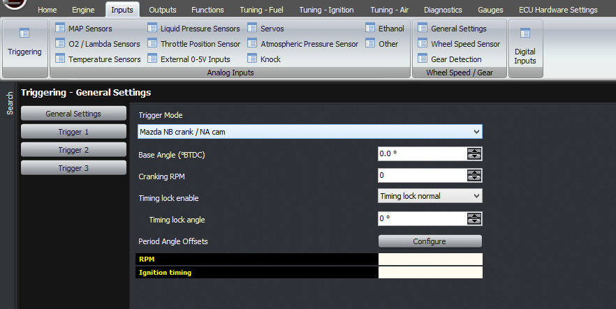
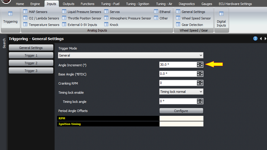
But this article is mostly about the generic trigger mode. In this mode, you will need to configure it yourself based on what’s on the actual engine. There are several variables that need to be known, which are the angle increment, the base angle, and the reset types.
First we’ll discuss sensor wiring and sensor types. Firstly, we should have the highest tooth count input connected to CAS1. This is the main trigger that the ECU will use for working out the engine angle, which affects ignition timing and so on. Using the trigger with the most teeth gives the most accuracy. For example, if you have a Toyota crank sensor engine with 12 teeth on the crank and 2 on one or two camshafts, then the 12 tooth crank sensor will need to connect to CAS1. If you have a 36-2 trigger on the crank, then that must connect to CAS1. Another example is the Mitsubishi / Mazda sensor with 4 teeth on the camshaft and either 1 or 2 for cylinder identification; the 4 tooth sensor needs to connect to CAS1 whereas the 1 or 2 trigger sensor must connect to CAS2. For the Nissan optical style triggers, they have their own dedicated trigger modes and they will accept either sensor output connected to either input, but following this protocol, the 360 window trigger would connect to CAS1.
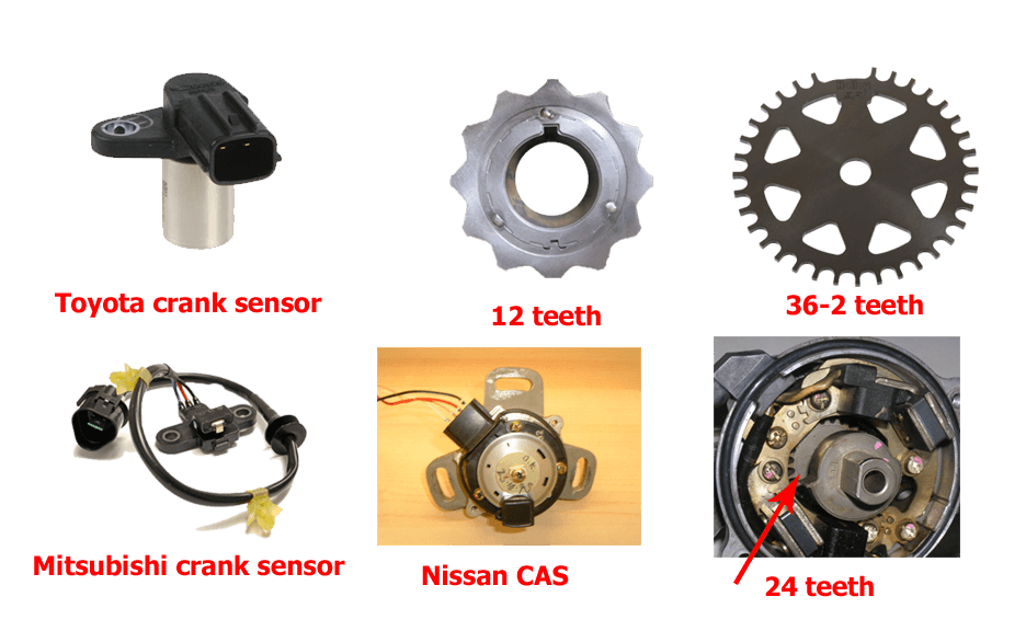
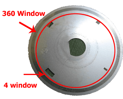
Sample Pictures Only
Secondly, there are broadly speaking 2 types of sensor output, as far as the ECU is concerned. The first is a variable reluctance sensor; also called reluctor, VR, or confusingly a “magnetic” sensor. These sensors have 2 pins on the sensor only. The sensor is a coil of wire and has an internal magnet. A tooth passing the sensor creates a change in reluctance, which causes a change in the magnetic field strength. This changing magnetic field creates a voltage in the coil, just like in an alternator. The voltage that the sensor generates is proportional to voltage; at 6000 RPM it will generate double the voltage as at 3000 RPM. From this you can extrapolate that the sensor generates no voltage when the engine is stopped. So one downside of this type of sensor is that with the engine stationary, you can’t tell from the output from the sensor whether it’s currently facing the trigger tooth or not.
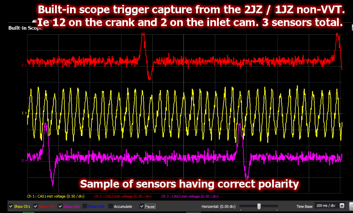
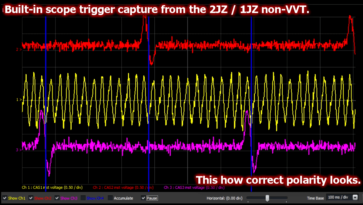
The other thing to be careful about with the reluctor sensors is that the polarity is important. The voltage should increase as the tooth approaches the sensor, and then when the tooth is facing the sensor, the voltage drops. When the tooth is in the middle of the sensor, the voltage is zero. Then the voltage goes negative, and finally as the tooth goes away from the sensor it goes back to zero. So the voltage goes positive, then negative through zero, then back to zero again. With a missing tooth trigger, you can tell the polarity during the missing tooth gap; the voltage should rise slowly through the gap because the ECU triggers off the negative zero crossing. With a multitooth trigger, where there is no missing tooth gap, the main thing to consider is the relative angle of CAS1 and the reset event. You can see both the polarity of the waveform and the relative timing on the built-in scope in the ECU.
The other type of sensor is a digital sensor. These can take the form of a an optical sensor, or a Hall effect sensor. In some cases there might also be reluctor sensors with built-in signal conditioning to give a digital output. In this case the sensor requires power, which may be 5V or 12V. When the sensor is triggered, it pulls the output to ground, and otherwise it doesn’t – therefore there must be a pull-up resistor in the ECU.
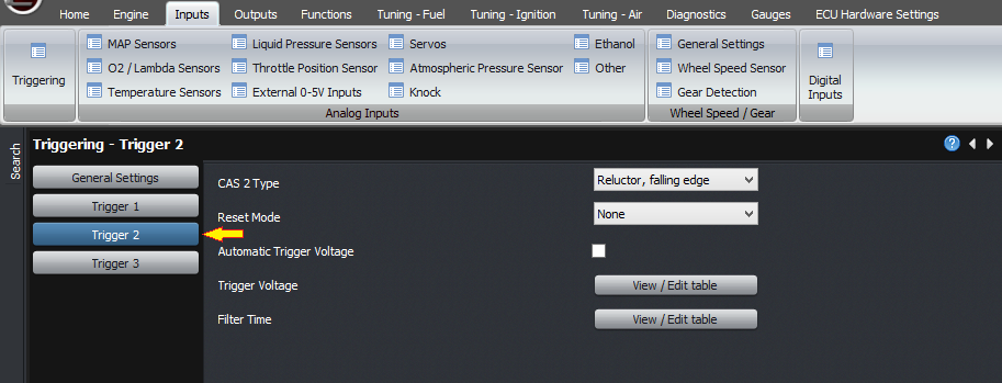
For both the reluctor and digital trigger types, you can adjust the voltage at which the ECU triggers. If this figure is too low, then the sensor will trigger off noise and cause triggering problems. If the figure is too high, then the sensor may not trigger at all, and this will cause triggering problems (for example, difficulty in starting). This threshold voltage can be adjusted against RPM. The ECU can also handle the threshold automatically, which is what we recommend unless there’s a problem.
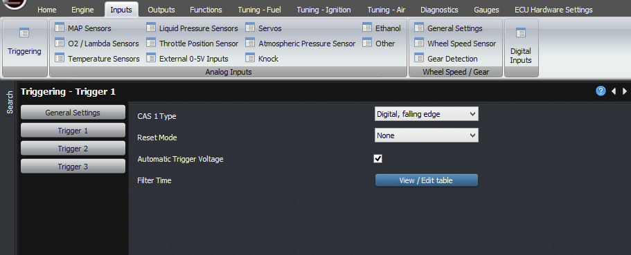
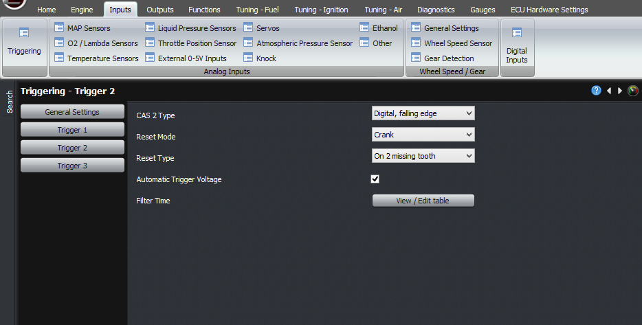
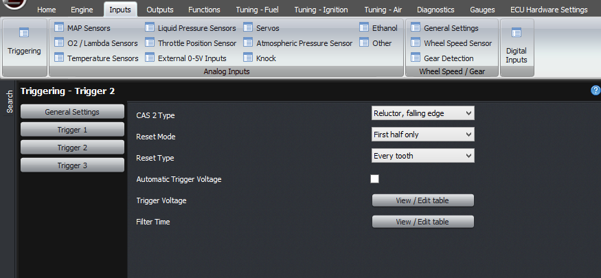
So in a generic trigger mode, you need to select that you’re using a generic trigger mode. This will open the trigger settings for each input. Next you can select each of your trigger inputs, and select whether it’s a digital or a reluctor input.
Then select the automatic voltage threshold option.
The next feature is the filtering. In general, you probably won’t need to touch this. Normally about 20 microseconds is a good duration to deal with ignition noise, but on very high tooth count engines like the Nissan optical sensors this will need to reduce to about 4 microseconds at high RPM.
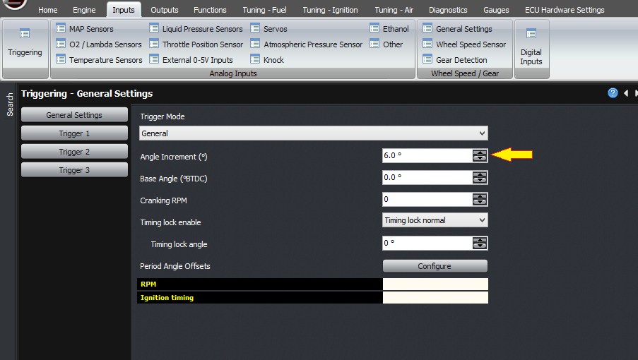
Now, we’ll look at how the ECU interprets these trigger events. The first setting we need to consider is the angle increment. This is the crank angle, in degrees between each of the CAS1 trigger events. For example if you have 12 teeth on the crankshaft, this value is 30 degrees. If you have 60-2 on the crank, then the value is 6 degrees. If the spacing is uneven (apart from missing teeth), you will need to use a dedicated trigger mode, not the generic trigger mode.
The next thing to consider is how the ECU will know when the engine is at TDC, ie where to start counting from. There will need to be some kind of reset event that occurs once per crank revolution, or once per cam revolution, that the ECU can use to know what angle the engine is at. If there is a missing tooth on the crank, then you will need to use that. In that case, set the reset type for Trigger 1 to be a crank type reset, and select either 1 or 2 missing teeth as appropriate for your engine.
In this case, the base trigger angle will be the angle BTDC of the first tooth after the gap. Now, being a 720 degree cycle and a crank sensor, this will occur twice within the 720 degree cycle. So there are two possible values; one value and the same value plus or minus 360 degrees. At this stage, just select one of them.
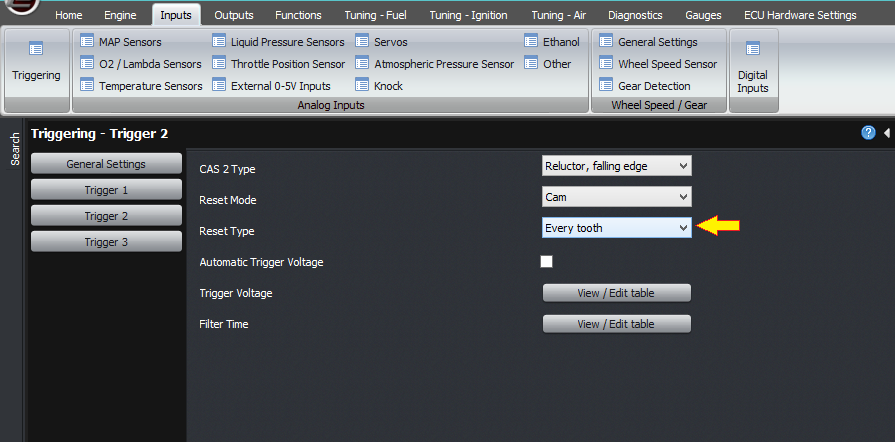
The other common case is where there is a single tooth on the cam, and no missing teeth on the crank. In this case, the reset type for trigger 1 must be “none”, and the reset type for “trigger 2” must be “cam”, and set to “every tooth” (rather than missing teeth). If it’s on the crank instead, then you should select “crank” instead of “cam”, for example the factory trigger on the RX7 FD engine.
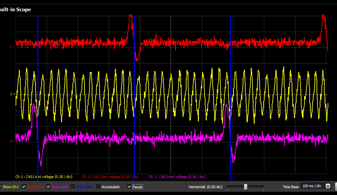
If you are using this trigger type with a multitooth and a cam reset, then you will need to check the relative trigger angles. You can do this using the built-in scope, during cranking. The important criterion is that the reset event (eg single tooth cam trigger) happens as far as possible from CAS1 trigger events. If you have a reluctor on CAS1, and its negative edge happens at almost the same time as the CAS2 reset trigger, then you may need to reverse the polarity of CAS1. Or similarly you may need to select the rising or falling edges differently on a digital trigger.
If you so far have only selected a crank type reset, for example if you have a missing tooth on the crank, and you are running a 4 stroke engine, then best results will be obtained by using a cam sensor as well so that the ECU can achieve 720 degrees of crank angle information. If it’s a single tooth, then select the trigger type as “first half only”.
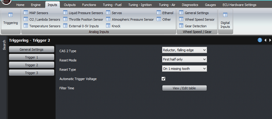
If it’s a missing tooth type sensor for example the Toyota 2ZZ or BEAMS which has 4-1 on the cam, you should select it as first half only, but select it as “reset on 1 missing tooth” rather than “reset on every tooth”.
Note that in first half only type reset, this only switches the ECU’s crank angle by 360 degrees or leaves it as is. There must be a separate reset, usually a crank type reset, to tell the ECU where TDC is.
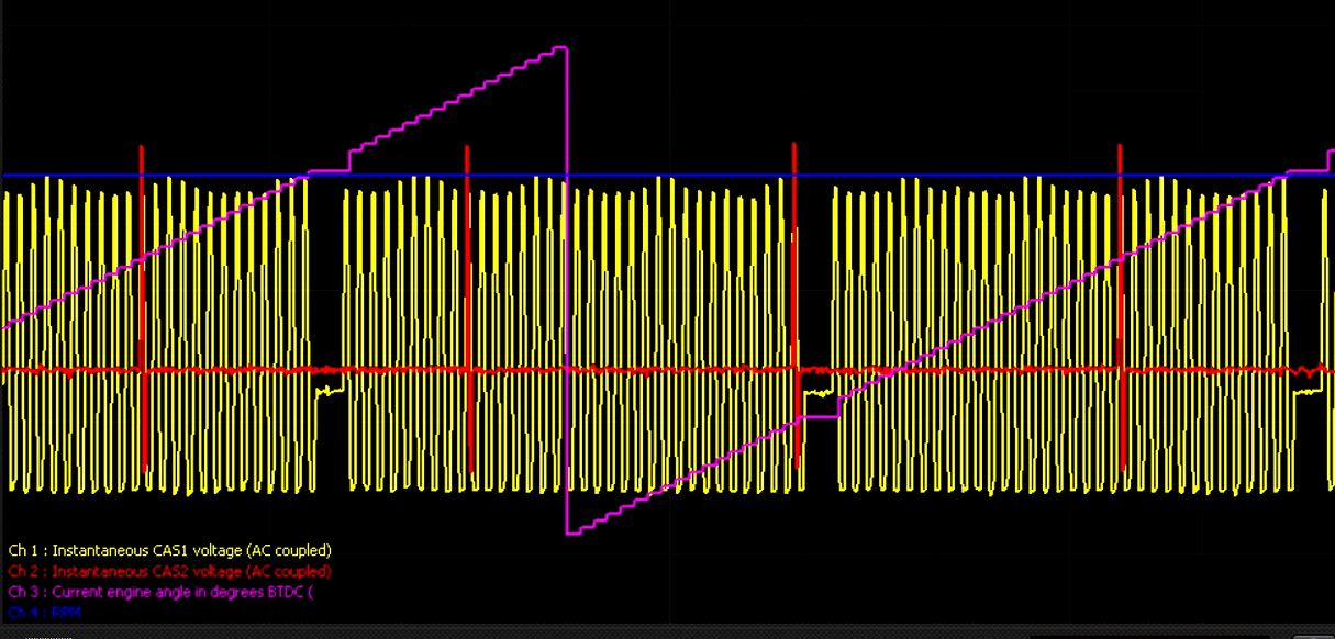
You can use the built-in scope to verify not only the trigger inputs, but also the ECU’s understanding of the current engine angle. As you can see here the crank angle estimated by the ECU goes up in steps where each step corresponds to another CAS1 trigger.
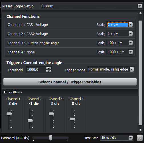
The typical scope settings you’ll need to see during cranking, are:
Channel 1: CAS1 inst voltage, 1V/div
Channel 2: CAS2 inst voltage, 1V/div
Channel 3: Current engine angle, 100/div
Timebase: 50ms per division
Once you have the correct triggering, you can set the base timing using the base angle setting. When cranking you should now have stable RPM.
The other setting that must be set correctly is the cranking RPM threshold. This must be higher than the actual cranking RPM with some margin. Once the RPM exceeds this value, the ECU considers the engine to be running, switches over to the main fuel map instead of the cranking map and so on.
The final thing we need to discuss with respect to trigger inputs is VVT. The ECU always records the crank angle of the CAS2 and CAS3 trigger events, and the CAS4 and CAS5 trigger events if you have the mini realtime expansion module. For digital triggers you will need to select the correct edge (positive or negative) to get stable readings.
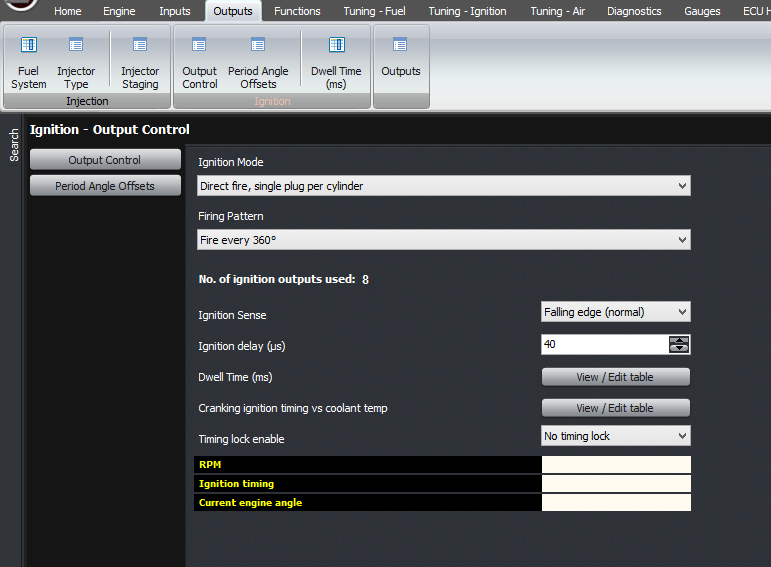
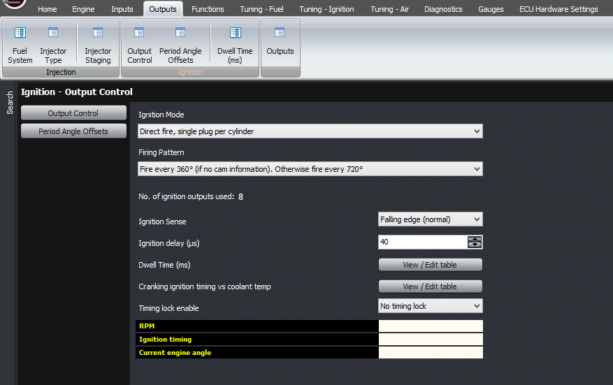
Reading the crank angle can be done with the factory timing marks, or making your own as we describe in another article, but how do you know whether it’s TDC ignition or TDC overlap? If you can see the cam pulleys then that might tell you, or you could put a hose into the spark plug hole and try blowing into it to see if the valves are closed. Another way, which I like because I don’t really like getting my hands too dirty, that works if you have a coil per plug system, is to start off the engine in wasted spark mode. Ie, set the ignition output firing pattern to 360 degrees instead of 720. With the engine running, change the ignition output firing to 720 and see if the engine stalls. If so, change the base timing setting by 360 degrees and try again. Once it’s only firing every 720 degrees, then you know it’s correct.
Finally, if you have a crank reset that occurs potentially a long time before the reset on the camshaft, which would be a “first half only” reset type, you can set the ignition output mode to fire every 360 degrees, until the cam sensor is triggered, and then switch over to 720 degrees. This gives you the nyeh-nyeh-vroom starting performance of a factory car.
Thank you and happy learning!
One thing that I always say is to make sure we understand the objective. What problem are we solving? The whole point of triggering is for the ECU to know the current engine angle as accurately as possible, and as quickly as possible from when the engine starts to crank. The more accurate the ECU’s knowledge of the engine angle, the more stable the ignition timing will be and the closer it can run to the ragged edge. The less rotation that the ECU requires from the triggering system before it knows the angle, the faster the engine will fire up from cranking.
The ECU always tracks the engine angle over a 720 degree period; and this is represented as a range from -360 to +360 degrees and then straight to -360 again. Zero degrees is defined as cylinder 1 TDC ignition. For 2-stroke engines, including rotaries, the ECU still calculates the engine over the 720 degree range but the injection and ignition is fired every 360 degrees.
There are several preconfigured triggers for various engines, so if your engine is listed then use it. Start with the base angle of zero degrees, and then fine tune the ignition timing using timing lock when the engine is running.
But this article is mostly about the generic trigger mode. In this mode, you will need to configure it yourself based on what’s on the actual engine. There are several variables that need to be known, which are the angle increment, the base angle, and the reset types.
First we’ll discuss sensor wiring and sensor types. Firstly, we should have the highest tooth count input connected to CAS1. This is the main trigger that the ECU will use for working out the engine angle, which affects ignition timing and so on. Using the trigger with the most teeth gives the most accuracy. For example, if you have a Toyota crank sensor engine with 12 teeth on the crank and 2 on one or two camshafts, then the 12 tooth crank sensor will need to connect to CAS1. If you have a 36-2 trigger on the crank, then that must connect to CAS1. Another example is the Mitsubishi / Mazda sensor with 4 teeth on the camshaft and either 1 or 2 for cylinder identification; the 4 tooth sensor needs to connect to CAS1 whereas the 1 or 2 trigger sensor must connect to CAS2. For the Nissan optical style triggers, they have their own dedicated trigger modes and they will accept either sensor output connected to either input, but following this protocol, the 360 window trigger would connect to CAS1.
Sample Pictures Only
Secondly, there are broadly speaking 2 types of sensor output, as far as the ECU is concerned. The first is a variable reluctance sensor; also called reluctor, VR, or confusingly a “magnetic” sensor. These sensors have 2 pins on the sensor only. The sensor is a coil of wire and has an internal magnet. A tooth passing the sensor creates a change in reluctance, which causes a change in the magnetic field strength. This changing magnetic field creates a voltage in the coil, just like in an alternator. The voltage that the sensor generates is proportional to voltage; at 6000 RPM it will generate double the voltage as at 3000 RPM. From this you can extrapolate that the sensor generates no voltage when the engine is stopped. So one downside of this type of sensor is that with the engine stationary, you can’t tell from the output from the sensor whether it’s currently facing the trigger tooth or not.
The other thing to be careful about with the reluctor sensors is that the polarity is important. The voltage should increase as the tooth approaches the sensor, and then when the tooth is facing the sensor, the voltage drops. When the tooth is in the middle of the sensor, the voltage is zero. Then the voltage goes negative, and finally as the tooth goes away from the sensor it goes back to zero. So the voltage goes positive, then negative through zero, then back to zero again. With a missing tooth trigger, you can tell the polarity during the missing tooth gap; the voltage should rise slowly through the gap because the ECU triggers off the negative zero crossing. With a multitooth trigger, where there is no missing tooth gap, the main thing to consider is the relative angle of CAS1 and the reset event. You can see both the polarity of the waveform and the relative timing on the built-in scope in the ECU.
The other type of sensor is a digital sensor. These can take the form of a an optical sensor, or a Hall effect sensor. In some cases there might also be reluctor sensors with built-in signal conditioning to give a digital output. In this case the sensor requires power, which may be 5V or 12V. When the sensor is triggered, it pulls the output to ground, and otherwise it doesn’t – therefore there must be a pull-up resistor in the ECU.
For both the reluctor and digital trigger types, you can adjust the voltage at which the ECU triggers. If this figure is too low, then the sensor will trigger off noise and cause triggering problems. If the figure is too high, then the sensor may not trigger at all, and this will cause triggering problems (for example, difficulty in starting). This threshold voltage can be adjusted against RPM. The ECU can also handle the threshold automatically, which is what we recommend unless there’s a problem.
So in a generic trigger mode, you need to select that you’re using a generic trigger mode. This will open the trigger settings for each input. Next you can select each of your trigger inputs, and select whether it’s a digital or a reluctor input.
Then select the automatic voltage threshold option.
The next feature is the filtering. In general, you probably won’t need to touch this. Normally about 20 microseconds is a good duration to deal with ignition noise, but on very high tooth count engines like the Nissan optical sensors this will need to reduce to about 4 microseconds at high RPM.
Now, we’ll look at how the ECU interprets these trigger events. The first setting we need to consider is the angle increment. This is the crank angle, in degrees between each of the CAS1 trigger events. For example if you have 12 teeth on the crankshaft, this value is 30 degrees. If you have 60-2 on the crank, then the value is 6 degrees. If the spacing is uneven (apart from missing teeth), you will need to use a dedicated trigger mode, not the generic trigger mode.
The next thing to consider is how the ECU will know when the engine is at TDC, ie where to start counting from. There will need to be some kind of reset event that occurs once per crank revolution, or once per cam revolution, that the ECU can use to know what angle the engine is at. If there is a missing tooth on the crank, then you will need to use that. In that case, set the reset type for Trigger 1 to be a crank type reset, and select either 1 or 2 missing teeth as appropriate for your engine.
In this case, the base trigger angle will be the angle BTDC of the first tooth after the gap. Now, being a 720 degree cycle and a crank sensor, this will occur twice within the 720 degree cycle. So there are two possible values; one value and the same value plus or minus 360 degrees. At this stage, just select one of them.
The other common case is where there is a single tooth on the cam, and no missing teeth on the crank. In this case, the reset type for trigger 1 must be “none”, and the reset type for “trigger 2” must be “cam”, and set to “every tooth” (rather than missing teeth). If it’s on the crank instead, then you should select “crank” instead of “cam”, for example the factory trigger on the RX7 FD engine.
If you are using this trigger type with a multitooth and a cam reset, then you will need to check the relative trigger angles. You can do this using the built-in scope, during cranking. The important criterion is that the reset event (eg single tooth cam trigger) happens as far as possible from CAS1 trigger events. If you have a reluctor on CAS1, and its negative edge happens at almost the same time as the CAS2 reset trigger, then you may need to reverse the polarity of CAS1. Or similarly you may need to select the rising or falling edges differently on a digital trigger.
If you so far have only selected a crank type reset, for example if you have a missing tooth on the crank, and you are running a 4 stroke engine, then best results will be obtained by using a cam sensor as well so that the ECU can achieve 720 degrees of crank angle information. If it’s a single tooth, then select the trigger type as “first half only”.
If it’s a missing tooth type sensor for example the Toyota 2ZZ or BEAMS which has 4-1 on the cam, you should select it as first half only, but select it as “reset on 1 missing tooth” rather than “reset on every tooth”.
Note that in first half only type reset, this only switches the ECU’s crank angle by 360 degrees or leaves it as is. There must be a separate reset, usually a crank type reset, to tell the ECU where TDC is.
You can use the built-in scope to verify not only the trigger inputs, but also the ECU’s understanding of the current engine angle. As you can see here the crank angle estimated by the ECU goes up in steps where each step corresponds to another CAS1 trigger.
The typical scope settings you’ll need to see during cranking, are:
Channel 1: CAS1 inst voltage, 1V/div
Channel 2: CAS2 inst voltage, 1V/div
Channel 3: Current engine angle, 100/div
Timebase: 50ms per division
Once you have the correct triggering, you can set the base timing using the base angle setting. When cranking you should now have stable RPM.
The other setting that must be set correctly is the cranking RPM threshold. This must be higher than the actual cranking RPM with some margin. Once the RPM exceeds this value, the ECU considers the engine to be running, switches over to the main fuel map instead of the cranking map and so on.
The final thing we need to discuss with respect to trigger inputs is VVT. The ECU always records the crank angle of the CAS2 and CAS3 trigger events, and the CAS4 and CAS5 trigger events if you have the mini realtime expansion module. For digital triggers you will need to select the correct edge (positive or negative) to get stable readings.
Reading the crank angle can be done with the factory timing marks, or making your own as we describe in another article, but how do you know whether it’s TDC ignition or TDC overlap? If you can see the cam pulleys then that might tell you, or you could put a hose into the spark plug hole and try blowing into it to see if the valves are closed. Another way, which I like because I don’t really like getting my hands too dirty, that works if you have a coil per plug system, is to start off the engine in wasted spark mode. Ie, set the ignition output firing pattern to 360 degrees instead of 720. With the engine running, change the ignition output firing to 720 and see if the engine stalls. If so, change the base timing setting by 360 degrees and try again. Once it’s only firing every 720 degrees, then you know it’s correct.
Finally, if you have a crank reset that occurs potentially a long time before the reset on the camshaft, which would be a “first half only” reset type, you can set the ignition output mode to fire every 360 degrees, until the cam sensor is triggered, and then switch over to 720 degrees. This gives you the nyeh-nyeh-vroom starting performance of a factory car.
Thank you and happy learning!
©2018 Adaptronic