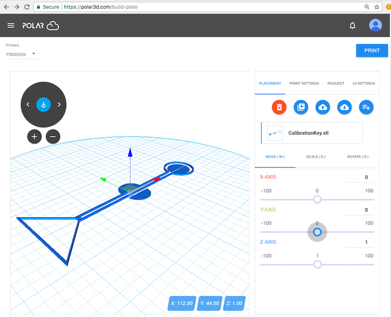
Figure 2.12: Build plate PLACEMENT: MOVE object
Once you choose an object to print and click the “3D PRINT” button on the object’s display screen (see Figure 2.10), you will be at a screen such as shown in Figure 2.11, where you have the opportunity to adjust your object, and adjust printer settings, if you wish.
There are many ways to adjust your object, as well as adjust printer settings, before printing. (The variety of possible adjustments are discussed in detail in Section 10.2: The build plate screen (3D PRINT), and adjusting your print of the Polar Cloud Guide.) For now, you may merely want to experiment with, and check, the following:
At the object build plate screen, see Figure 2.11, check that “PLACEMENT” is highlighted (in blue), meaning that placement is the active mode; if necessary, click on “PLACEMENT” to select it.
Click on the object image on the build plate screen, or click on the object name on the right underneath “PLACEMENT. Clicking either place will bring up a set of colored axes (red x-axis, green y-axis, blue z-axis) superimposed on the object image, and three tabs will appear in the right pane (or lower pane on mobile or small displays) under “PLACEMENT”: “MOVE (W)”, “SCALE (E)”, and “ROTATE (R)”. Check that “MOVE” is highlighted (in blue), meaning that it is selected; clicking on “MOVE”, (or clicking the W key), will select it; see Figure 2.12.
To move the object’s desired placement on the build plate, you may do whichever is most convenient:
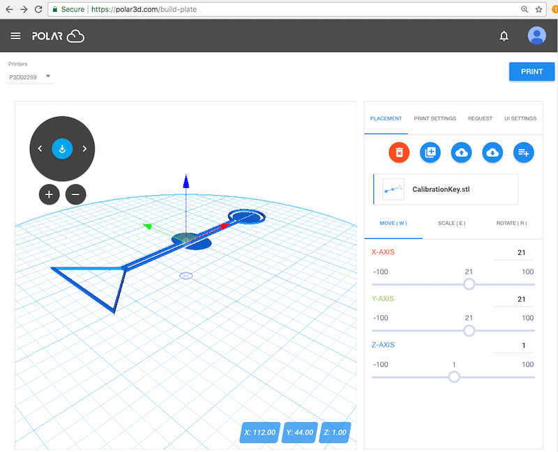
While in general objects are best printed offset from the center of the Polar3D printer build plate (thereby avoiding blemishes from any suboptimal calibration at the build plate center , (see Section 14.1.1: Position objects towards the edge of the Polar3D printer build plate of the Polar Cloud Guide), the CalibrationKey object, as it intended to test and display any calibration issues, is best printed with its center at the center of the build plate. Figure 2.13 shows the CalibrationKey moved to be centered on the build plate.
At the object build plate screen, see Figure 2.11, check that “PLACEMENT” is highlighted (in blue), meaning that placement is the active mode; if necessary, click on “PLACEMENT” to select it.
Click on the screen where the object image is shown on the build plate. This will bring up a set of colored axes (red x-axis, green y-axis, blue z-axis) superimposed on the object image, and three tabs will appear in the right window under “PLACEMENT”: “MOVE (W)”, “SCALE (E)”, and “ROTATE (R)”. Click on “SCALE” (or click the E key) to select it; (check that “SCALE” appears highlighted in blue indicating that it is selected); see Figure 2.14.
You may choose to scale the object’s overall size uniformly along all axes, or scale the object differently along different axes: see the “Scale all axes uniformly” checkbox below the “SCALE” tab. To adjust the object’s size, you may: move the slider position on an axis in the right-hand pane, enter a new numeric value at an axis in the right-hand pane, or you may click on an axis in the left-hand, object view pane, and then drag to change the size along that axis as desired.
At the object build plate screen, see Figure 2.11, the dial towards the upper left of the left-hand (object on build plate) screen in effect “rotates the build plate” – it rotates your view of the object. The two small buttons underneath the dial allow you to zoom in and zoom out on your view of the object and build plate.
(Note that this rotation of your view of the build plate and the object on it is distinct from rotating the object’s placement on the build plate – that latter operation, rotating the placement of the object while keeping the build plate stationary, is instead controlled via the “ROTATE (R)” tab under “PLACEMENT”.)
Try clicking on the left arrow and right arrow on the dial to rotate the build plate (and the object on it), and try clicking on the circled “+” button below the dial (to zoom in) and the circled “-” button below the dial (to zoom out). You may also click-and-drag the build plate image itself (clicking on the build plate, rather than on the object on the build plate) and to rotate your view of the build plate, or use mouse or trackpad “scrolling” to zoom in or out on the build plate display.
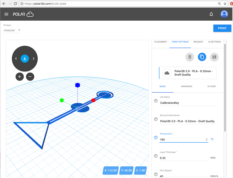
At the object build plate screen, see Figure 2.11, clicking “PRINT SETTINGS” in the right-hand window will bring up three tabs: “BASIC”, “ADVANCED”, and “G-CODE”. The temperature which the printer is set to use for printing is displayed under the “BASIC” display, as shown in Figure 2.15.
The proper temperature for the PLA filament provided by Polar 3D on a Polar3D printer is 185°C. (If you are using a different type of filament, see the filament manufacturer’s recommendation for what temperature to use for it.)