Open Loop MOP Control for RX7s and MOP Control for RX8s on Modular ECUs

This article describes how it is
possible to do open loop MOP control on a rotary engine using
a Modular ECU.
Firstly, we don’t recommend this except for testing purposes. Mazda included a position sensor on the metering oil pump so that it could be closed loop controlled, and also on the RX8, if the factory ECU detects a metering oil pump failure, it limits the throttle authority to 5%. If you’re not running premix then the engine will have the wrong amount of lubrication.
Let’s start by discussing the types of metering oil pumps.
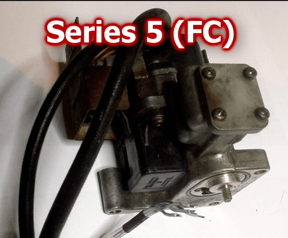
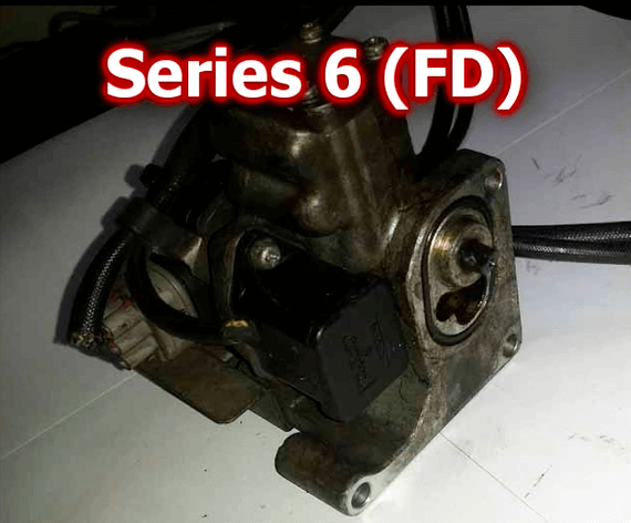
Firstly, the series 5 (FC) and the series 6 (FD) are mechanically very similar. They look the same except for a slightly different part number, 198700-0050 for the series 5 and 198700-0060 for the series 6 – and also the Series 6 has a single connector for the motor and sensor, whereas the series 5 has separate connectors for the sensor and the motor.
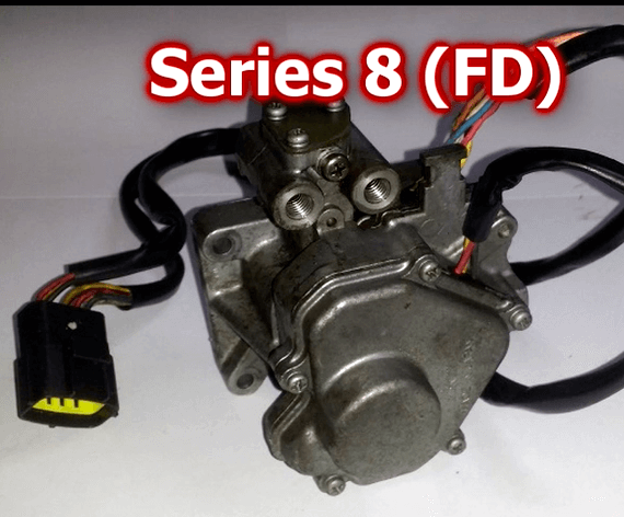
The series 8 (FD) has the same connector as the series 6, but looks quite different as you can see in this picture. There’s no plastic housing, and there’s no heat shield.
All of the RX7 oil metering pumps are 72-step devices, with a position sensor that gives an analogue output proportional to the position of the oil metering pump.
The wire colours are shown below, both the wire colours in the loom and on the pump itself (the colours are not the same either side of the connector). The table also shows what they need to connect to in the ECU to make them work.
Loom (car) Loom (MOP) ECU connection
B/O W MOP stepper A (ign 6 on plugin RX7 ECU)
B/Lg L MOP stepper A inverted
B/L Y MOP stepper B (ign 5 on plugin RX7 ECU)
B/Y B MOP stepper B inverted
B/W R 12V power
B/W R/W 12V power
Br/B B SGND
Br/W L +5V
G/B Y Signal (position), connect to 0-5V input eg Servo
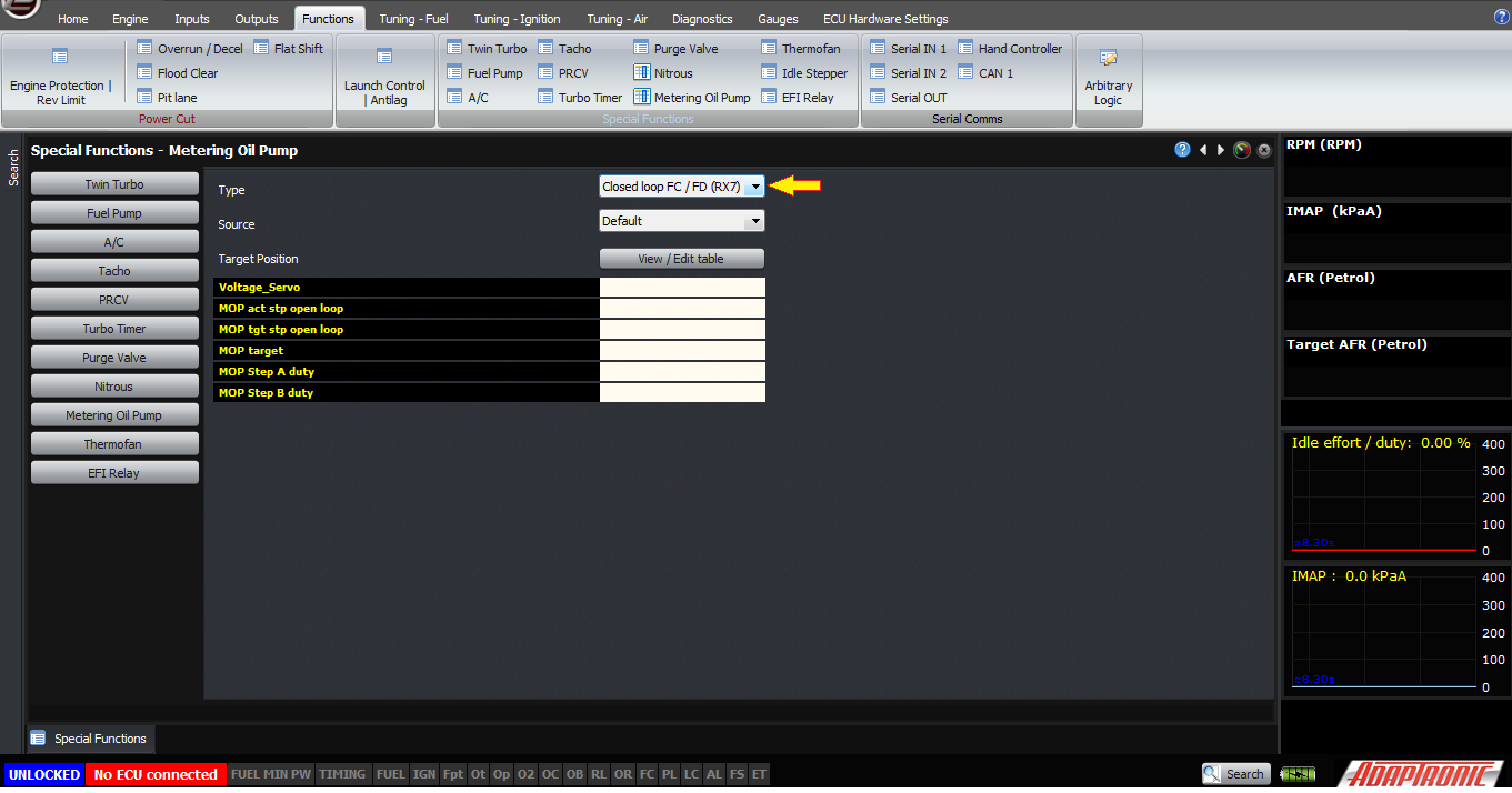
The default mode for the metering oil pump is closed loop mode.
Firstly, we don’t recommend this except for testing purposes. Mazda included a position sensor on the metering oil pump so that it could be closed loop controlled, and also on the RX8, if the factory ECU detects a metering oil pump failure, it limits the throttle authority to 5%. If you’re not running premix then the engine will have the wrong amount of lubrication.
Let’s start by discussing the types of metering oil pumps.
Firstly, the series 5 (FC) and the series 6 (FD) are mechanically very similar. They look the same except for a slightly different part number, 198700-0050 for the series 5 and 198700-0060 for the series 6 – and also the Series 6 has a single connector for the motor and sensor, whereas the series 5 has separate connectors for the sensor and the motor.
The series 8 (FD) has the same connector as the series 6, but looks quite different as you can see in this picture. There’s no plastic housing, and there’s no heat shield.
All of the RX7 oil metering pumps are 72-step devices, with a position sensor that gives an analogue output proportional to the position of the oil metering pump.
The wire colours are shown below, both the wire colours in the loom and on the pump itself (the colours are not the same either side of the connector). The table also shows what they need to connect to in the ECU to make them work.
Loom (car) Loom (MOP) ECU connection
B/O W MOP stepper A (ign 6 on plugin RX7 ECU)
B/Lg L MOP stepper A inverted
B/L Y MOP stepper B (ign 5 on plugin RX7 ECU)
B/Y B MOP stepper B inverted
B/W R 12V power
B/W R/W 12V power
Br/B B SGND
Br/W L +5V
G/B Y Signal (position), connect to 0-5V input eg Servo
The default mode for the metering oil pump is closed loop mode.
Closed loop mode
In this mode, the target table is a percentage travel of the sensor from 0.764V to 4.207V. If the sensor tells the ECU that it’s more than 2% away from the target, then the ECU will execute a step. The step period is 15ms if the motor is more than 5% away from the target, otherwise the step period is 20ms. If the measured position is within 2% of the target then the ECU drives both outputs with 50% duty cycle so as to reduce heating in the motor windings.
The ECU will also automatically change the phase of the two MOP step outputs if, after 1000 steps, the motor has not reached its target.
The ECU can now also drive the motor in an open loop manner, in a similar way to an idle control stepper motor. Of course with an open loop system, there’s no position sensor, so the ECU must “home” the motor by driving it fully in one direction or the other. Because when an engine starts it will generally start at idle, we drive the motor fully closed and then use that as the zero position. The target position in the map is still a percentage, but it’s now a percentage of the number of steps, the motor being a 72 step device. So numbers should be in the range of 0 – 100. Unlike with the closed loop system, zero is the minimum and represents the factory oil quantity at idle. In this mode, the step period is fixed at 15ms. During testing and characterisation, the pumps behaved correctly (ie, did not skip poles) right down to 10ms step periods but 15ms allows some margin. When the motor is at the target step, the ECU will again PWM both outputs at 50% to minimise heating. If another step is to be taken, the ECU first reasserts the logic levels for the current step for one period to make sure that a pole is not skipped.
Note that because there’s no sensor so the ECU doesn’t know where the motor is, if you reverse the phases of the motor winding there’s no way for the ECU to know this and you’ll just have the wrong amount of oil injected.
The same control method can be used for the RX8 series 1 oil metering pump, which again even though it looks quite different from the RX7 oil metering pumps, is still a 72 step device.
These open loop modes are selected using the MOP type selection in the software, and because all devices are 72 step devices, all three modes have the same logical function.
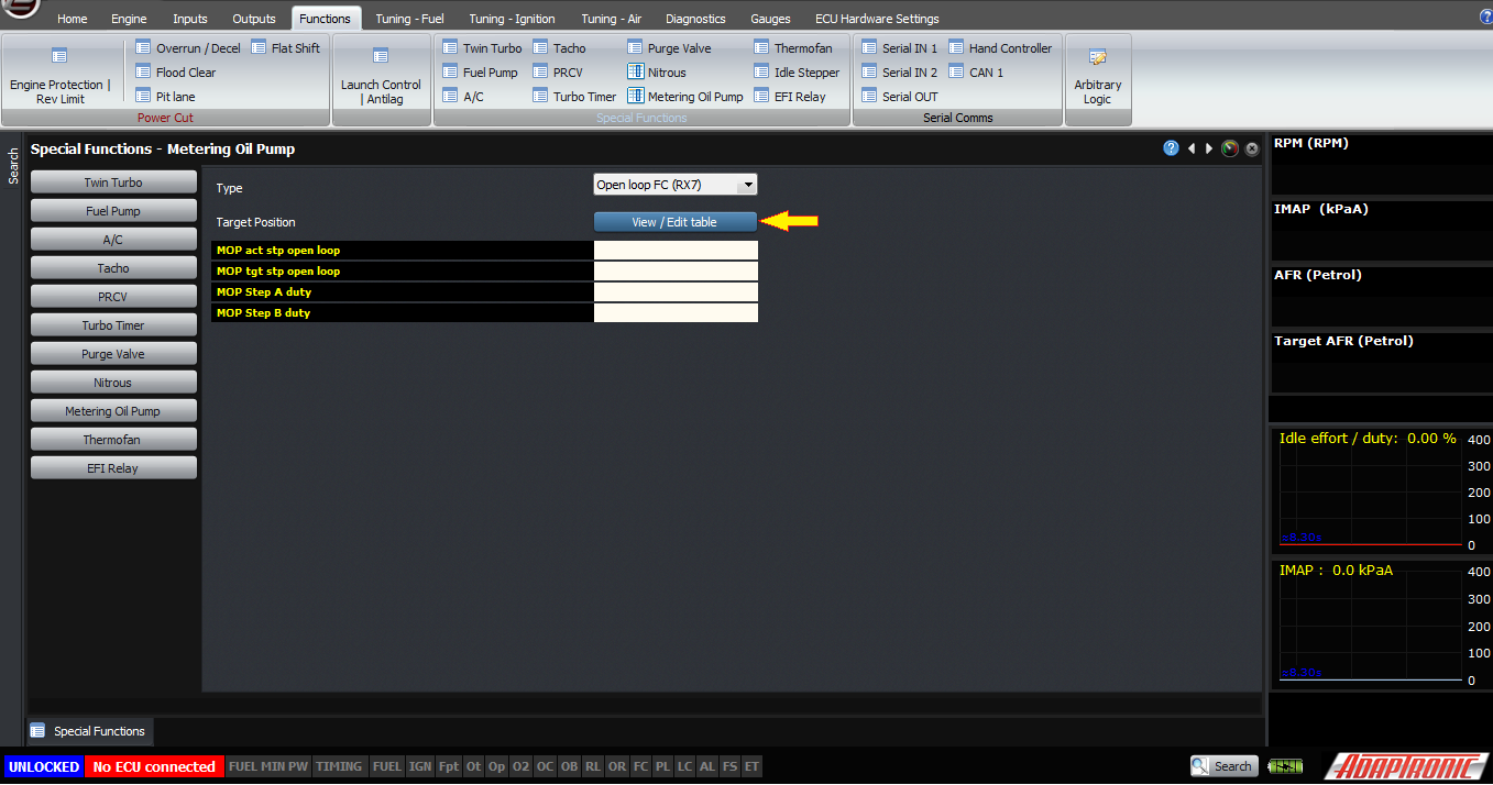
Open loop mode
Loom (car) Loom (MOP) ECU output
B/O Y MOP stepper A (Add out 6, 2W on plugin RX8 RCU)
L/Y L MOP stepper A inverted(Add out 5, 2V on plugin RX8 RCU)
B/L B MOP stepper B (Add out 8, 2AB on plugin RX8 RCU)
R/G W MOP stepper B inverted(Add out 7, 2Y on plugin RX8 RCU)
W/R R 12V power
W/R O 12V power
The last method we will describe is the closed loop RX8 metering oil pump control.
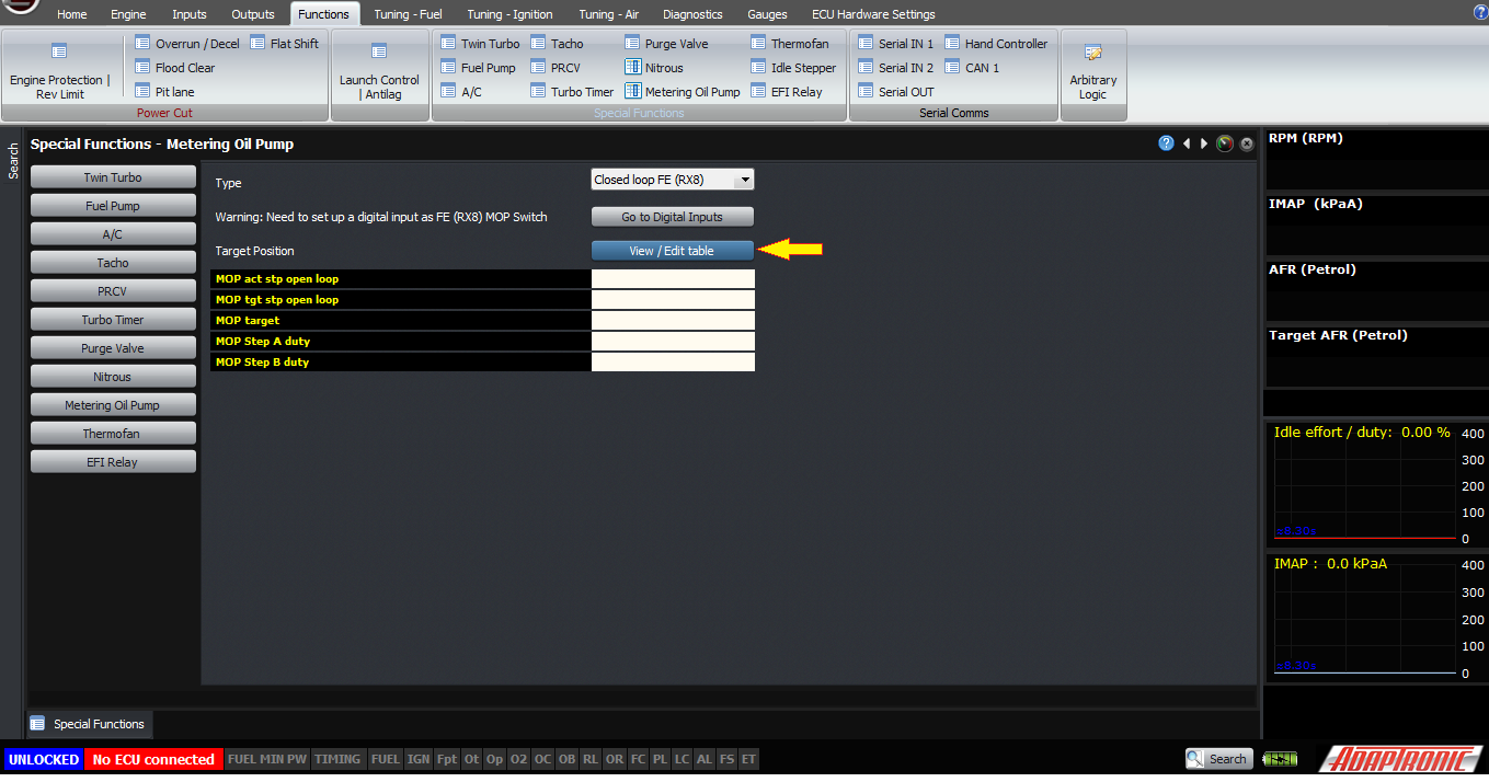
Closed loop FE mode
The RX8 pump has a switch, rather than a position sensor, to measure the position of the motor, and this switch changed state around step number 58 according to the documentation. The ECU can use this to “home” the stepper position at startup, and it also uses this to reset the step number when it passes the switch point later. However other than these conditions, the RX8 motor is operated as a stepper, where the ECU remembers the current step number and counts the steps – as there is no linear feedback for the ECU. For this mode, the outputs need to be configured as described before, although the wire colours are different on the RX8 pump – but also we need a digital input to be assigned as an RX8 metering oil pump position switch input. This connects to pin A on the MOP sensor connector, with pin C connecting to sensor ground.
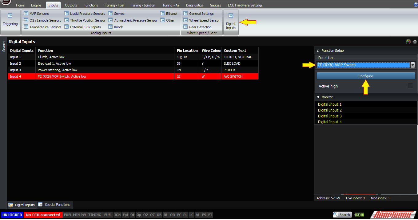
B/Y pin A Digital input (2N on plugin RX8 ECU)
Br pin C SGND (1U on plugin RX8 ECU)
pin B (no connection)
Again, this is primarily for diagnosis as these sensors are known to fail so please don’t use this if you’re not intimately familiar with rotary engines.
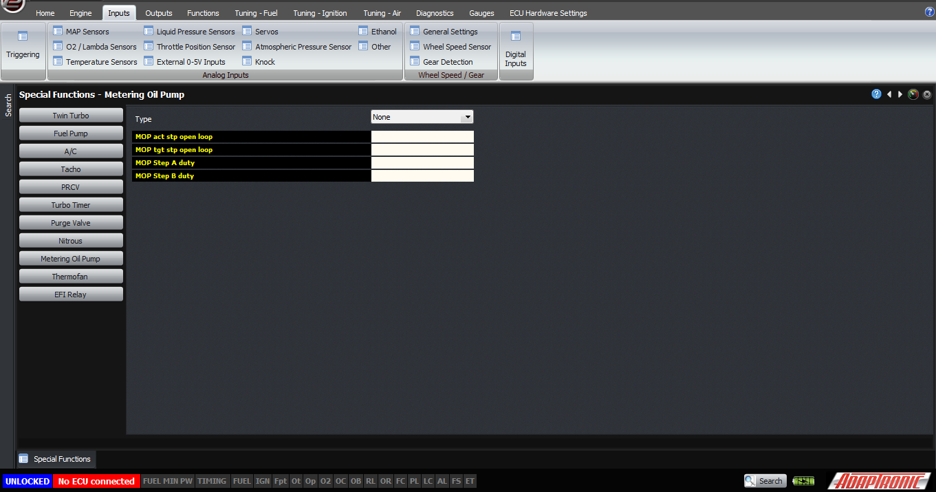
Finally, the “none” mode can be used to disable the MOP output, and in that case both outputs will be driven with 50% duty cycle.
Thank you!
©2018 Adaptronic