Metering Oil Pump Control on Mazda Rotary Engines with Modular ECUs

In this article we’ll discuss how to
set up the metering oil pump on the RX7 13B engines.
First of all, let’s discuss the function of the metering oil pump, MOP or oil metering pump, OMP (Mazda use the two terms interchangeably in different documents). It’s a mechanical device which allowed pressurised oil to be fed from the oil system to be fed into the rotor housings in the inlet area. It’s driven by a stepper motor, whose position determines the amount of oil that gets injected. There’s also a position feedback sensor on the pump that measures the position of the pump, and the ECU controls the stepper motor to achieve a certain position reading on the feedback sensor. This article does not cover the oil metering on the series 1 and series 2 RX8 engines, both of which are different from the RX7 engines, and also different from each other.
First of all, let’s discuss the function of the metering oil pump, MOP or oil metering pump, OMP (Mazda use the two terms interchangeably in different documents). It’s a mechanical device which allowed pressurised oil to be fed from the oil system to be fed into the rotor housings in the inlet area. It’s driven by a stepper motor, whose position determines the amount of oil that gets injected. There’s also a position feedback sensor on the pump that measures the position of the pump, and the ECU controls the stepper motor to achieve a certain position reading on the feedback sensor. This article does not cover the oil metering on the series 1 and series 2 RX8 engines, both of which are different from the RX7 engines, and also different from each other.
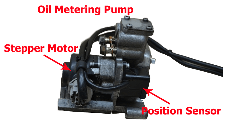
Oil Metering Pump of RX7 13B
The connections to the pump are as follows.
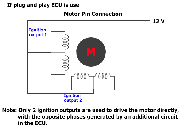
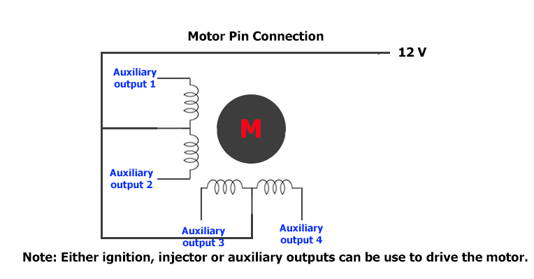
There is a 6 wire stepper motor which drives back and forward to control the amount of oil delivered. Like other 6 wire stepper motors, the middle pin on each row is 12V power and the two pins other side must be driven in opposite phases. So you will need an output for each of the 4 drive pins on the motor, that is an ignition, injector or auxiliary output. On the plug and play ECUs, only 2 ignition outputs are used to drive the motor directly, with the opposite phases generated by an additional circuit in the ECU. This allows you to run the motor using only 2 outputs out of the 20 available rather than 4.
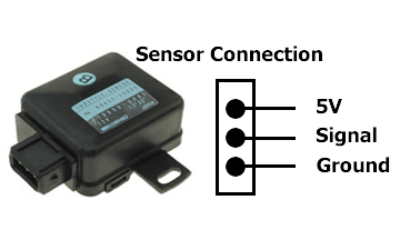
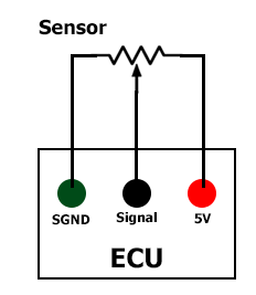
On the sensor side, the device is a 3 wire potentiometer, similar to a TPS, so the sensor needs sensor ground, 5V supply and a signal connection. By default the ECU will use the servo input, but you can use any 0-5V input on the ECU for the MOP position feedback input. This is all handled in the factory wiring of a plug and play ECU anyway.
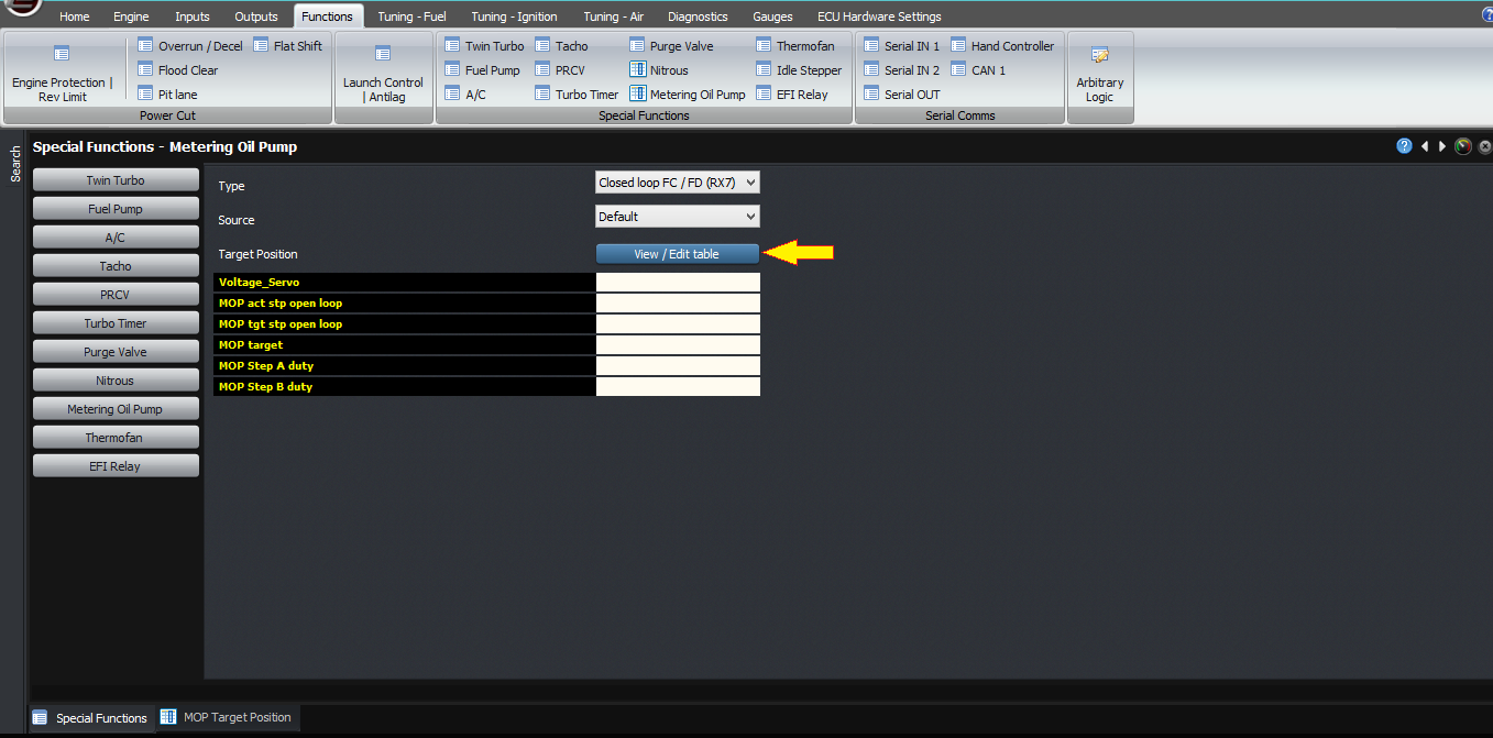
Let’s discuss the settings required for the MOP to work. Firstly, you need to select the input channel for the position sensor, ie where you have wired the position sensor to. If you select “default” then the ECU will assume it’s wired to the servo input, which is how it’s configured on the plug-in ECUs.
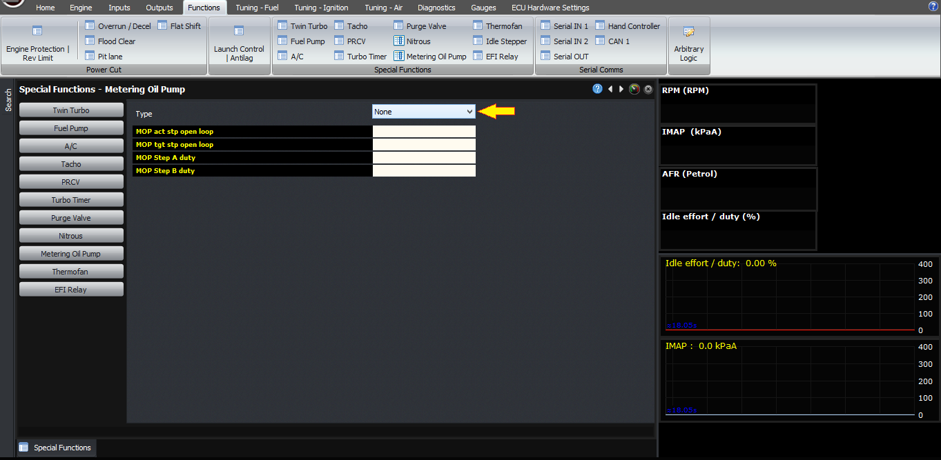
Source set to default
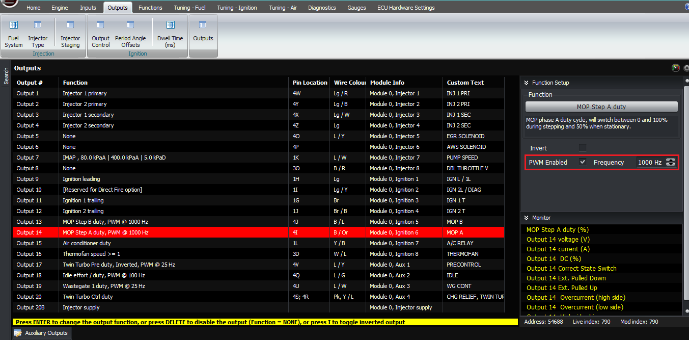
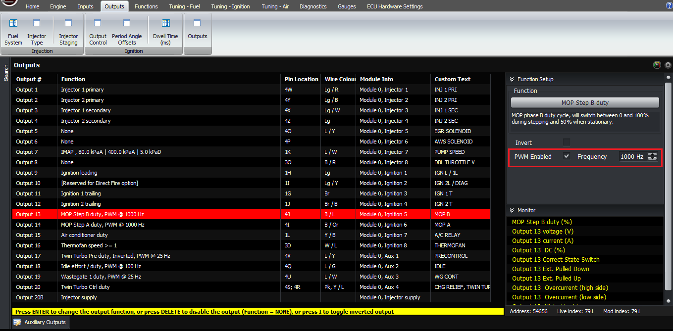
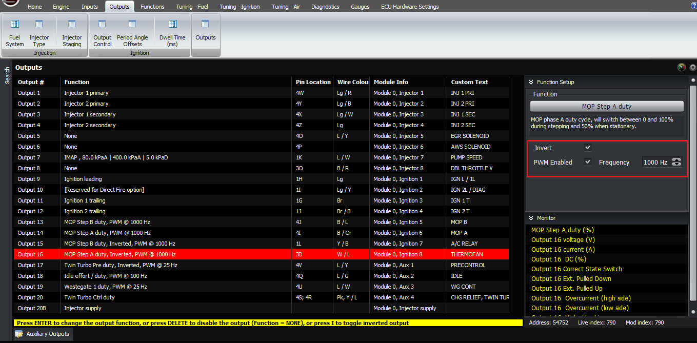
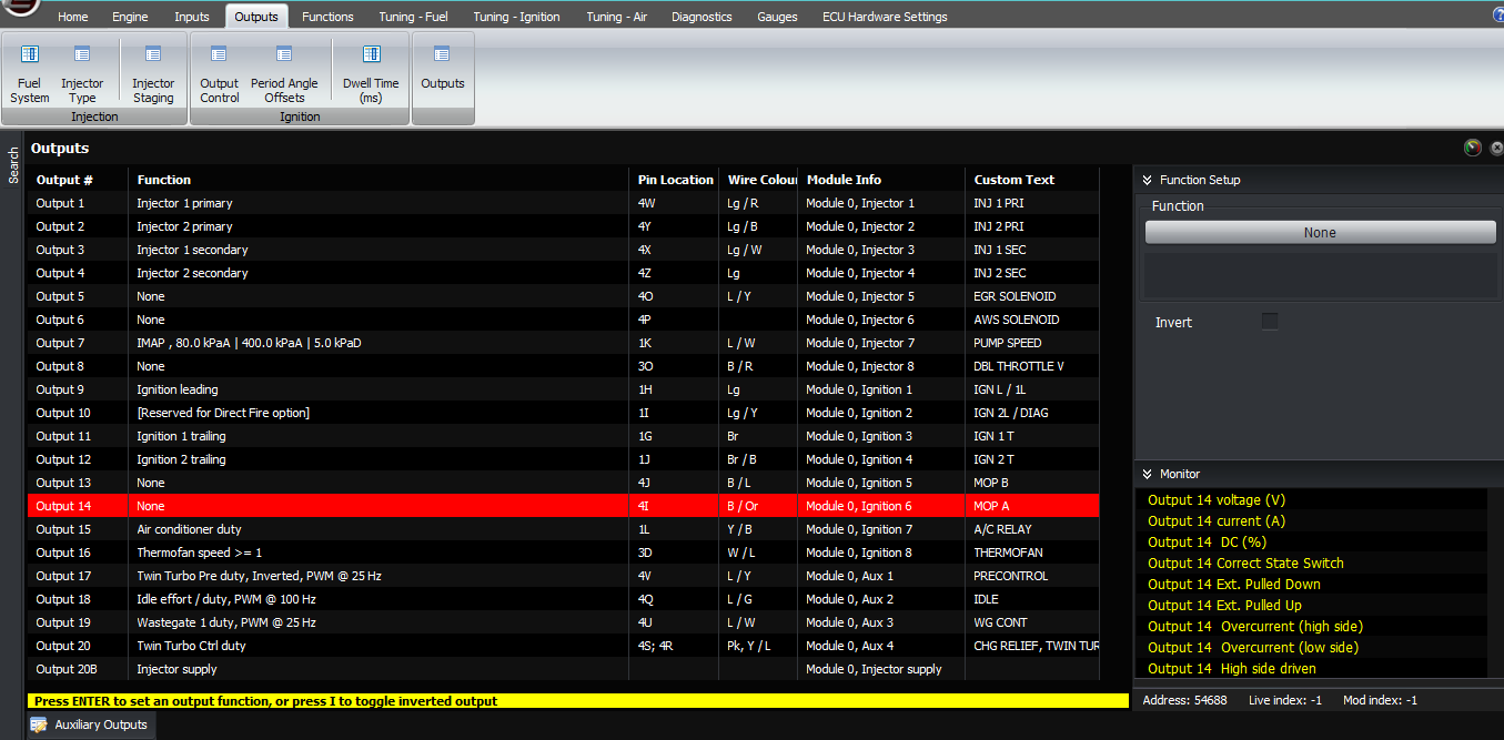
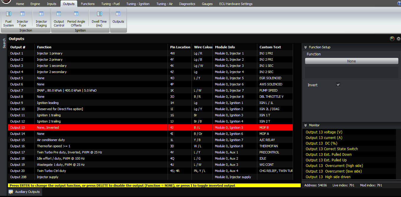
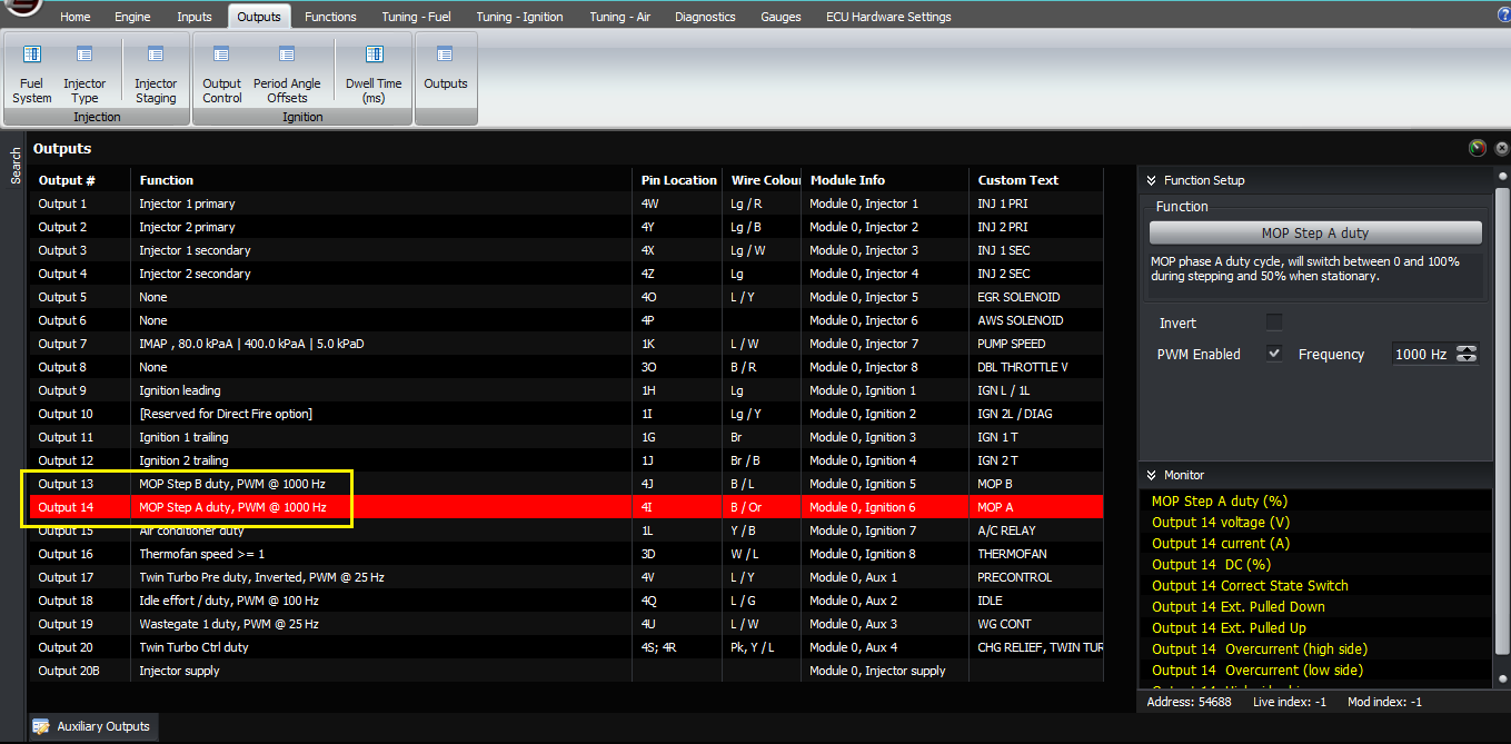
In terms of outputs, if you’re using a plug-in ECU which already has the circuitry to drive the other two phases, you need to select one of these outputs as MOP step A, and the other as MOP step B. Configure them as PWM at 1 kHz for reasons I’ll explain a bit later.
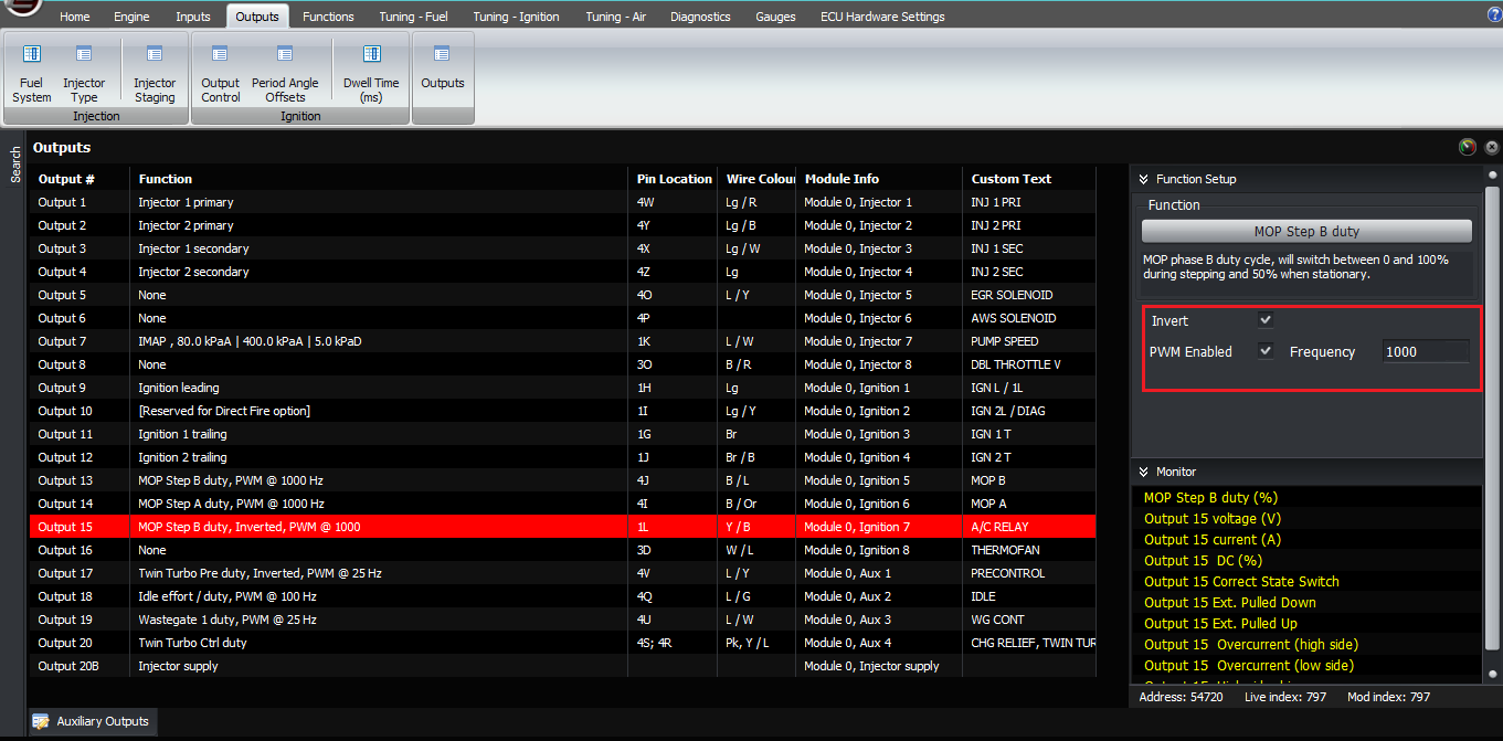
If you don’t have extra hardware to drive the boards then you need to set the other two outputs to be metering oil pump step A inverted and metering oil pump step B inverted, both are PWM enabled at 1kHz.
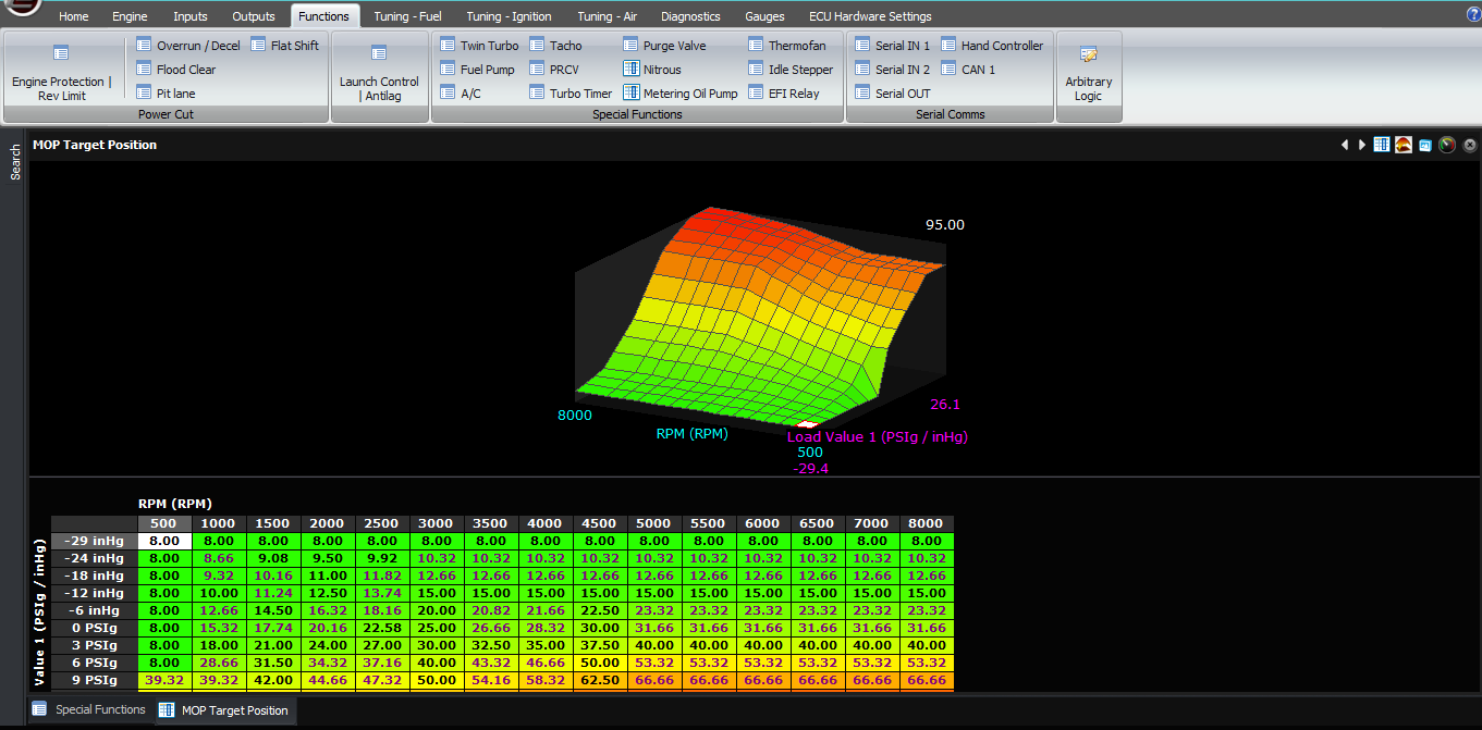
The final setting is the target MOP table, which is a function of RPM and manifold pressure. This table has been calculated by monitoring the behaviour of the factory ECU on the series 5 and series 6 engines; I understand that different types of seals have different oiling requirements so you may need to premix as well, please consult your engine builder or seal supplier if you’re unsure. The factory behaviour is that the amount of oil injected increases with RPM and with MAP, in other words it’s roughly related to the fuel quantity delivered, which also makes sense intuitively because people use premix.
Now, let’s discuss how to check that it’s working correctly. The ECU will chase the target value by driving the stepper motor outputs. If it drives for a long time and ends up in the wrong direction, it switches the outputs around and tries to go the other way. When the ECU is driving the motor forwards and backwards, the outputs are driving high and low alternately, so you will see the MOP step A and B numbers flicking between 0 and 100%. This happens too fast to be able to see the individual steps in a PC based log, but you can see them using the built-in scope or a real scope.
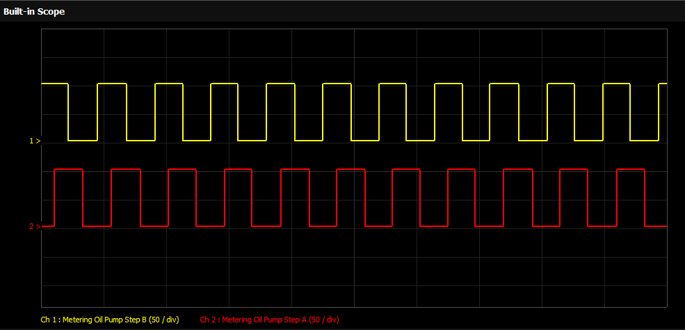
When the ECU gets to within a small error band of the target, it drives both outputs with a 50% duty cycle. This uses the coil inductance to reduce heating in the motor windings, compared to leaving one coil energized the whole time. So when it’s at the target you should see 50% on both outputs. If it happens to move either side of the target, it will take a step back or forward as required.
Let’s discuss how to diagnose a problem with the MOP. The most likely problem, based on the support questions we get, if the ECU configuration is correct, is going to be wiring. So firstly check the basics, ie:
-
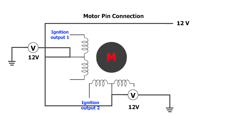
The two motor +12V pins have 12V on them
-
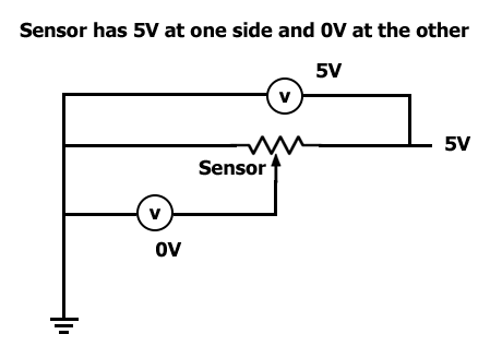
The sensor has 5V at one side and 0V at the other
-
The sense wire is connected through to the input on the ECU – for example when you short it to 5V, you can see the input change to 5V on the F11 ECU data screen
Firstly go to the outputs page and select Outputs 13 and 14 as being “none” rather than “MOP”. Follow the following tables to check the voltages (on the different models):
First test: Both outputs set to none:
| Series 5 ECU | Series 6 ECU | Series 8 ECU | Voltage
(approx) |
Internal connection | |||
| ECU pin | ECU pin | ECU pin | Wire col | Wire col | Wire col | ||
| 4T | B / L | 4J | B / L | 1W | B / L | 12V | Ign 5 (op 13) |
| 4V | B / R | 4L | B / Y | 1AE | B / Y | 0V | Ign 5 invert |
| 4S | B / Or | 4I | B / Or | 1S | B / Or | 12V | Ign 6 (op 14) |
| 4U | B / G | 4K | B / Lg | 1AA | B / Lg | 0V | Ign 6 invert |
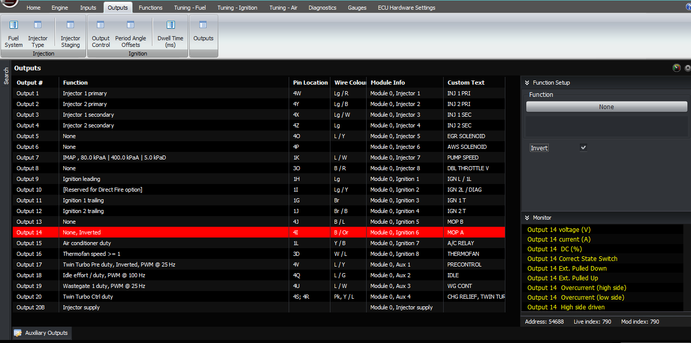
Second test: Set output 13 to “none, invert”
| Series 5 ECU | Series 6 ECU | Series 8 ECU | Voltage
(approx) |
Internal connection | |||
| ECU pin | ECU pin | ECU pin | Wire col | Wire col | Wire col | ||
| 4T | B / L | 4J | B / L | 1W | B / L | 0V | Ign 5 (op 13) |
| 4V | B / R | 4L | B / Y | 1AE | B / Y | 12V | Ign 5 invert |
| 4S | B / Or | 4I | B / Or | 1S | B / Or | 12V | Ign 6 (op 14) |
| 4U | B / G | 4K | B / Lg | 1AA | B / Lg | 0V | Ign 6 invert |
Third test: Put output 13 back to “none”, set output 14 to “none, invert”
| Series 5 ECU | Series 6 ECU | Series 8 ECU | Voltage
(approx) |
Internal connection | |||
| ECU pin | ECU pin | ECU pin | Wire col | Wire col | Wire col | ||
| 4T | B / L | 4J | B / L | 1W | B / L | 12V | Ign 5 (op 13) |
| 4V | B / R | 4L | B / Y | 1AE | B / Y | 0V | Ign 5 invert |
| 4S | B / Or | 4I | B / Or | 1S | B / Or | 0V | Ign 6 (op 14) |
| 4U | B / G | 4K | B / Lg | 1AA | B / Lg | 12V | Ign 6 invert |
If an output always shows 0V, then that normally means that there is an open circuit coil in the pump motor, or that there’s a disconnection between the motor and the ECU (for example a broken wire or a bad connection).
Finally, put the settings back to their standard values (output 13 = Metering Oil pump Step B, output 14 = Metering Oil Pump Step A).
If all of those pass, then the ECU is driving the outputs correctly, so the next step would be to check the pump itself, for open circuit windings or mechanical problems.
Additional information when using wire-in ECUs.
Make sure to follow the diagram below when wiring the oil metering pump on RX7 FCs and FDs .
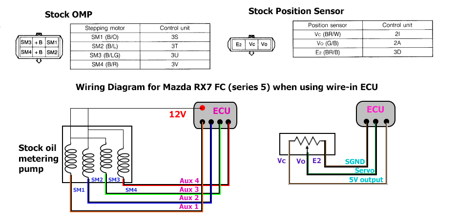
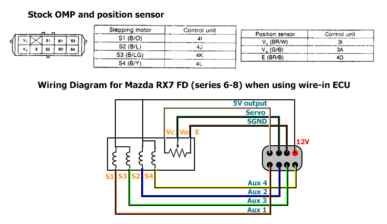 Next
configure either auxiliary, ignition or injector outputs to
drive your motor. In this example let’s use auxiliary outputs.
Select output 17 and 18 and configure it as “Metering Oil Pump
Step A” and “Metering Oil Pump Step B”, both should be
set as PWM at 1kHz. Then select output 19 and 20 as
“Metering Oil Pump Step A, inverted” and “Metering Oil
Pump Step B, inverted”, both should also be set as PWM at
1kHz.
Next
configure either auxiliary, ignition or injector outputs to
drive your motor. In this example let’s use auxiliary outputs.
Select output 17 and 18 and configure it as “Metering Oil Pump
Step A” and “Metering Oil Pump Step B”, both should be
set as PWM at 1kHz. Then select output 19 and 20 as
“Metering Oil Pump Step A, inverted” and “Metering Oil
Pump Step B, inverted”, both should also be set as PWM at
1kHz.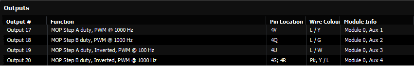
Thank you and happy learning!
©2018 Adaptronic