Setting Up Closed Loop Fuel Control on Modular ECUs

All Adaptronic ECUs support closed
loop fuel control. This article explains what is required and
how to configure it.
Firstly, and this should be obvious but I’ll say it anyway, you have to have your target lambda set correctly in your target lambda map.
Secondly, you need some kind of lambda measurement. Normally this would be a wideband lambda sensor, because with a narrowband you can really only know which side of lambda 1 you are, so doing closed loop for another mixture is not possible.
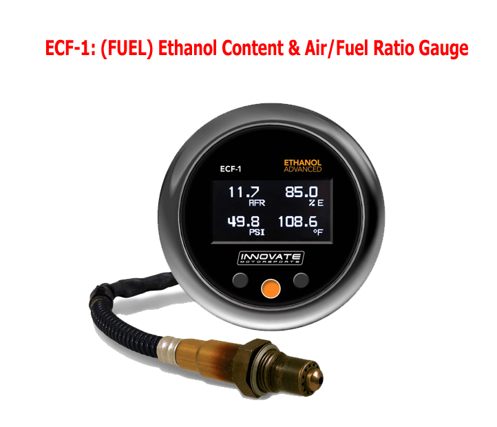
Sample of wideband sensor
If you are running a dual bank engine, then we would recommend enabling the separate bank setting in the engine settings, and running a separate lambda sensor on each bank. Make sure you set the bank configuration correctly, ie whether the cylinder numbers are numbered odd and even or first half and second half. The first oxygen sensor must be for the bank which has cylinder 1 in it (eg the odd bank), and the second one must be the other bank. This also works on engines such as the RB26DETT, which has a separate oxygen sensor for the front and the back halves of the engine, and in this case the bank numbering would be set as first half / second half, so that one “bank” is 123 and the second “bank” is 456. Also in this mode the oxygen sensor type should be set to “individual”.
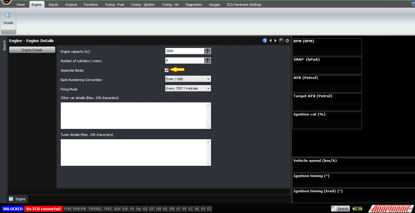
Enabling separate banks mode

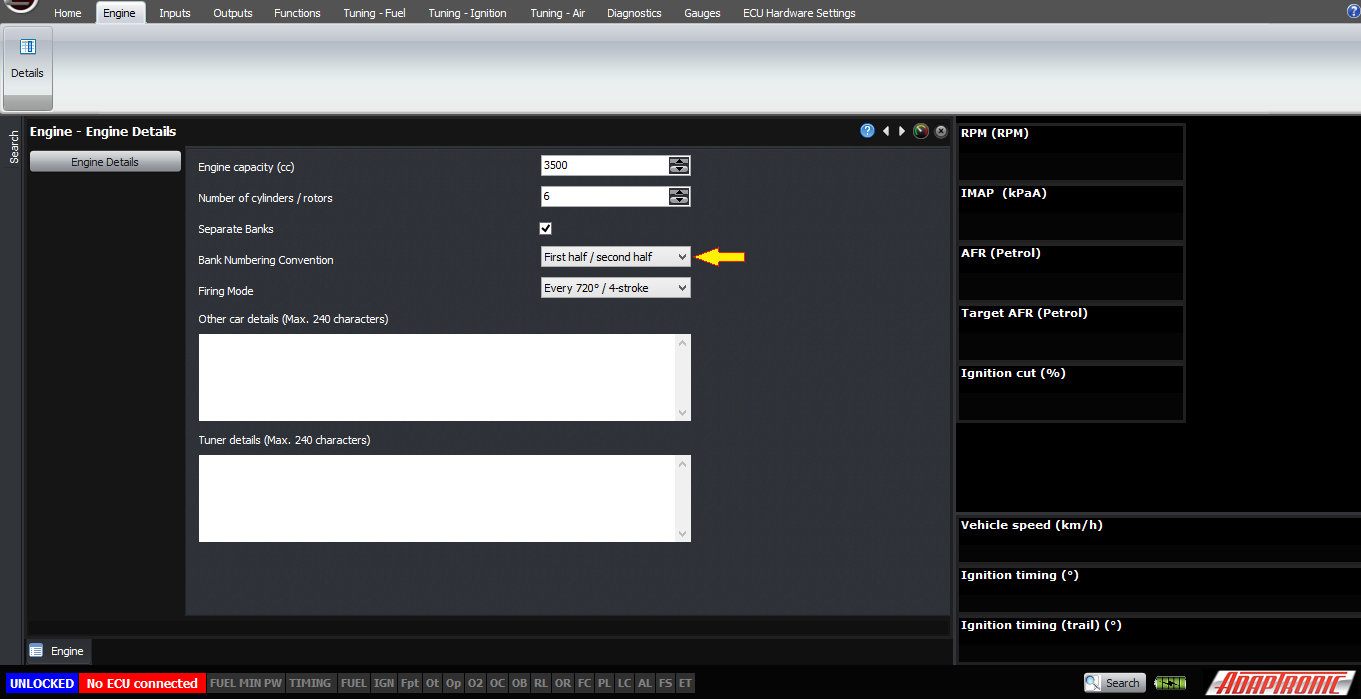
Select appropriate bank number convention for your engine
Other articles and videos explain how to set up various wideband lambda sensors so I won’t go into that here.
The ECU needs some conditions to be met before it will consider a lambda reading to be “valid”. If the input is not valid then the software will just show a dash instead of a lambda value and the ECU will be forced into open loop mode. These conditions are different for different sensors.
- A 0-1V sensor must exceed X V for Y sec to be considered working.
- A 0-5V sensor must exceed X V for Y sec to be considered working.
- An Innovate wideband must be sending packets, and the data in the packets must show a valid AFR or lambda value. If this is true then it will display an actual AFR or lambda value in Logworks. Note that if the sensor is in free air, an MTX-L gauge will display a full lean reading, even though it won’t send a lambda value out the serial stream (it sends the O2 concentration instead)
- For the widebands that send data out the serial stream but do not send the sensor status, for example Zeitronix, AEM and PLX, the ECU just needs to see valid serial data. If there’s valid serial data then the ECU trusts the sensor, even though when the sensor is cold, the controller for this devices outputs an incorrect lambda value.
- For the CAN wideband inputs, they must show that the sensor is online and working.
- When the engine is stopped, or cranking
- When the engine is in ignition or fuel cut
- If there’s no valid reading from the lambda sensor
- If the mode selected is “open loop”
- If the RPM is higher than the maximum RPM selected for closed loop
- If the load is either higher than the maximum or lower than the minimum required for closed loop
- If the coolant temperature is lower than the minimum ECT selected for closed loop
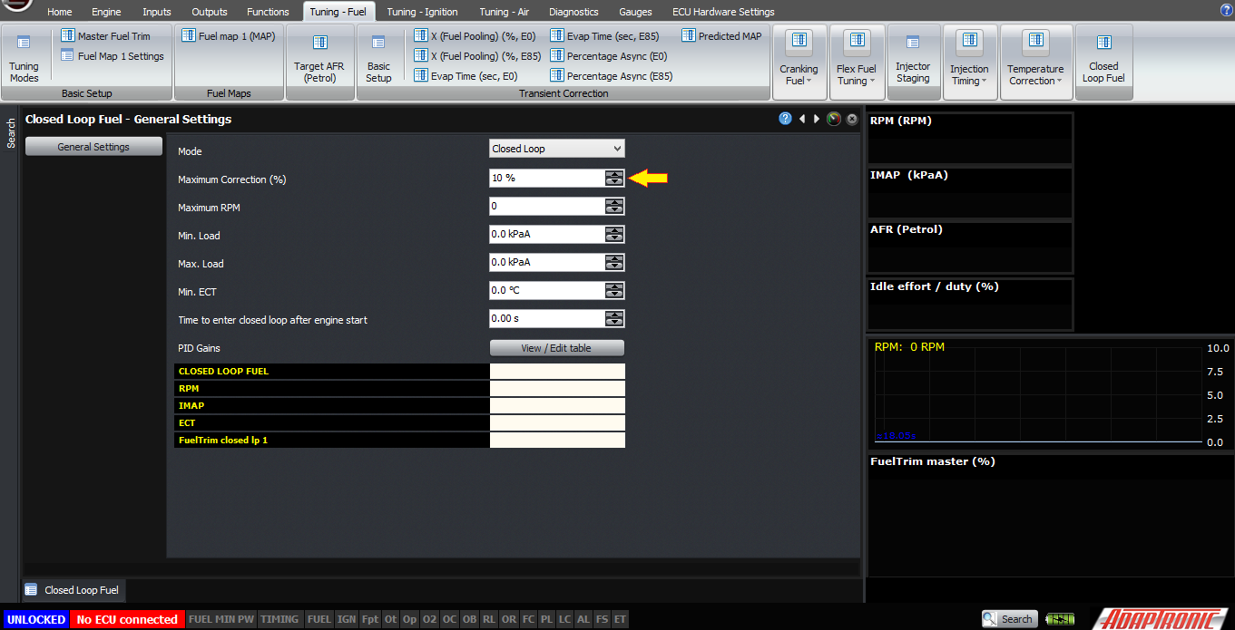
If you have met the conditions required, then the ECU will go into closed loop mode, and you can see this on the closed loop general settings page. You can also see here the variables that allow or prevent closed loop operation such as RPM, load and coolant temperature, as well as the closed loop fuel trim for each bank.
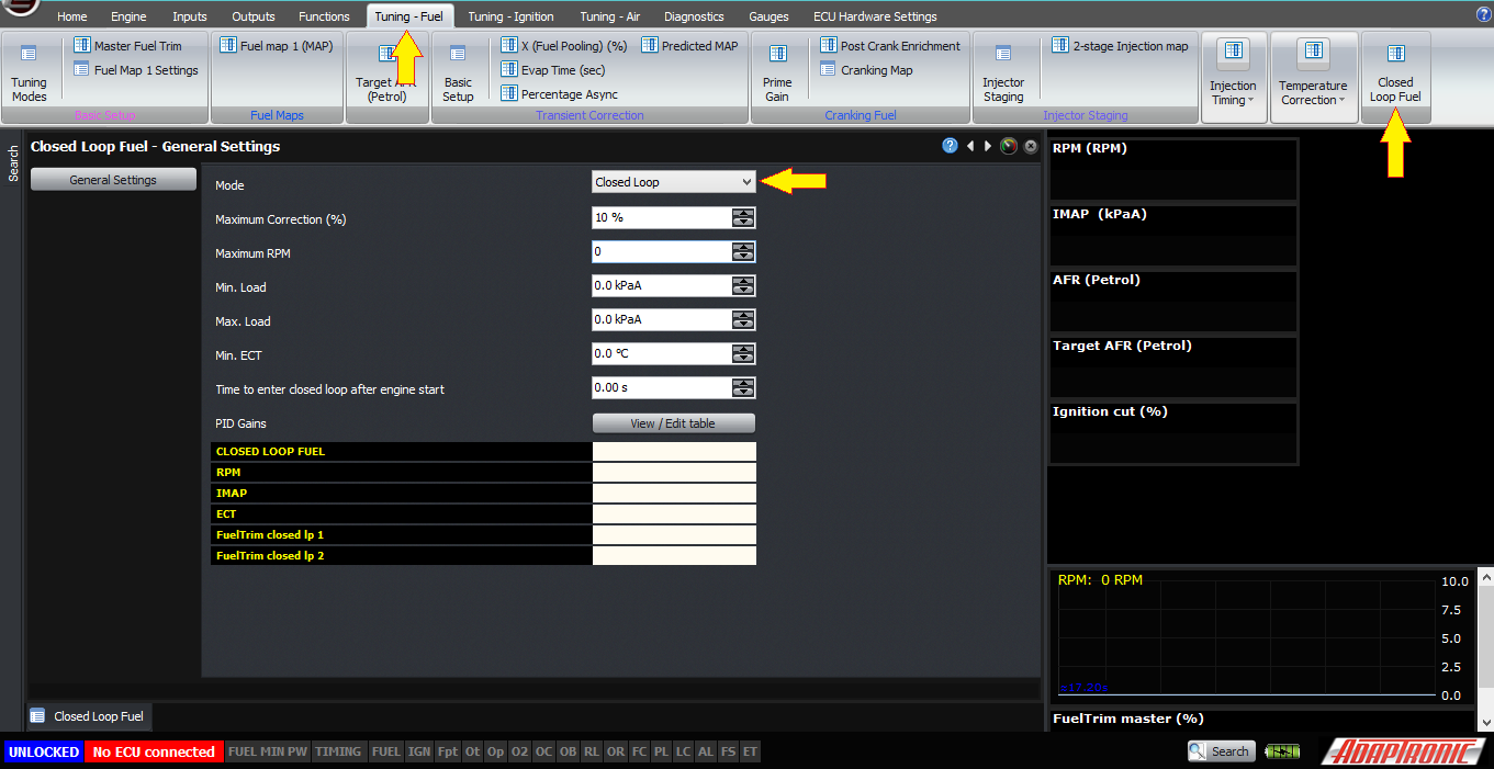
The PID gains can be set against RPM, for example often the engine will develop a rich-lean closed loop hunt at idle if you use the gains optimised for higher RPM operation. Typical values we would use for the PID gains would be 50% for P and I, and 0 for D.
50% value fo P and I
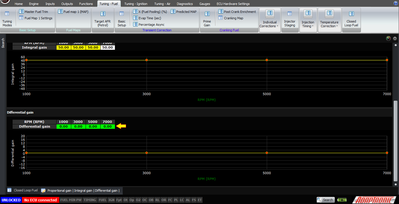
0% is set for D
Another setting you may want to adjust is the maximum correction percentage. This changes the amount of correction that the ECU can provide due to the closed loop behaviour. Typical values might be 10 or 20%.
Finally, please remember that closed loop is not supposed to be a substitute for having a good fuel map. It will help with systematic changes that affect the mixture for which you haven’t accounted, but if you have one part of the map that’s rich and another that’s lean, and you go to the rich part and let the closed loop stabilise, then when you go to the lean part it will be extra lean. So if you’re tuning manually then generally you’d have closed loop turned off, so you can see what the map itself is doing rather than how well the closed loop can correct it.
Thank you!
©2018 Adaptronic