Setting up Closed Loop Idle Control on Modular ECUs

Closed loop idle control is one of
the things that makes a car nice to drive when it’s set up
nicely and working correctly. So in this article we’ll
describe what you need to do to set it up.
Firstly, the ECU needs to know whether to go into closed loop idle or not. I’ve explained this in other places but for the sake of completeness I’ll include it here as well. It’s not enough to know that the throttle is closed, for the following reason. Imagine you’re in a situation where you’re in gear, for example at 2000 RPM, coming to a stop sign. Your foot is off the throttle. If the ECU went into closed loop idle in this circumstance, it would see that the engine is at 2000 RPM, which is too high compared to the target of 800 RPM, so it would reduce the idle effort. The RPM would remain unchanged so it would reduce the idle effort further. Eventually the idle effort would be all the way down to zero but the RPM would still be too high. Then as you put your foot on the clutch to stop at the stop sign, the engine stalls because the idle effort is zero where it might actually need 40% to idle properly.
Really the ECU needs to know if the engine is at the current RPM because it’s idling there, or because it’s being driven there by some outside force, like the wheels. Some cars are set up nicely from the factory and include a clutch switch and a neutral switch so that the ECU can tell if the engine is disconnected from the wheels, and will only go into closed loop idle if either the clutch is pressed or the gearbox is in neutral. Many other manufacturers don’t have these, but they have a vehicle speed input to the ECU, and the ECU will only go into closed loop idle if it detects the car is stationary.
The Modular ECU will go into closed loop in either of these conditions, but also the throttle must be closed (that is, the CLOSED THROTTLE flag on the TPS inputs page must be active), and either it must have fallen close to the target idle RPM, or if it hasn’t, then these conditions must have been met for a minimum amount of time, which is called the neutral timeout. The neutral timeout must be set so that the engine has enough time to fall from maximum RPM back to idle; otherwise the ECU will go into closed loop before the engine has got back down to idle, with a corresponding dip in the RPM, or possibly even a stall. A value of 5 seconds would be typical.


Let’s look at the settings required. Firstly we need to enable closed loop idle.
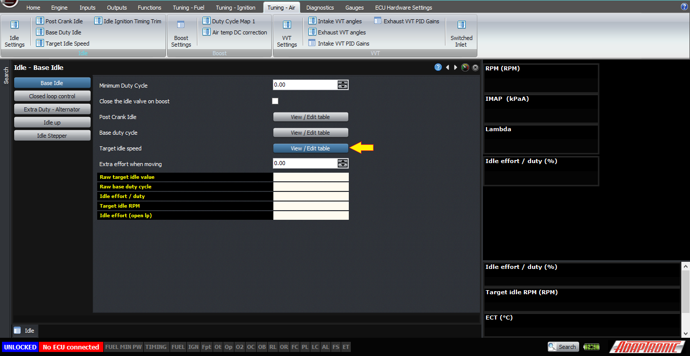
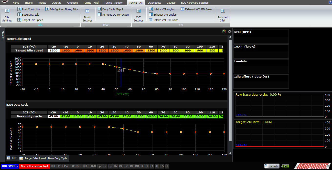
Secondly, we need to have our target idle speeds set in the target idle speed table. These can be varied against coolant temperature, and overridden by electrical loads, air conditioner activation and so on.
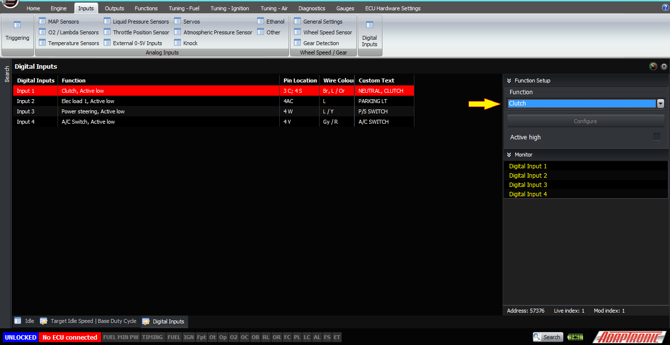
Next, we need to make sure that our closed loop conditions are configured correctly. If your car has neutral or clutch switches, then they can be connected to a digital input and configured as “clutch” type input. Functionally they mean the same thing, so they can usually be connected in parallel to the one input unless you have some other reason not to. If you don’t, then you will need to have a working wheel speed sensor input, and there’s another article explaining how to set this up.
Also please check that the closed throttle flag is working correctly. Sometimes aftermarket throttles get sticky and don’t always return to the same position, and sometimes there’s backlash between the throttle shaft and the sensor which means the TPS reading doesn’t reliably go back to zero when you close the throttle. Issues like this will cause problems setting up closed loop idle.

The neutral timeout has to be set, as I mentioned before, about 5 seconds is a good time.
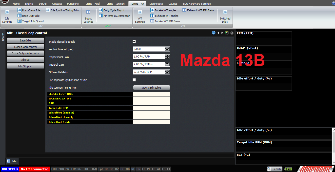
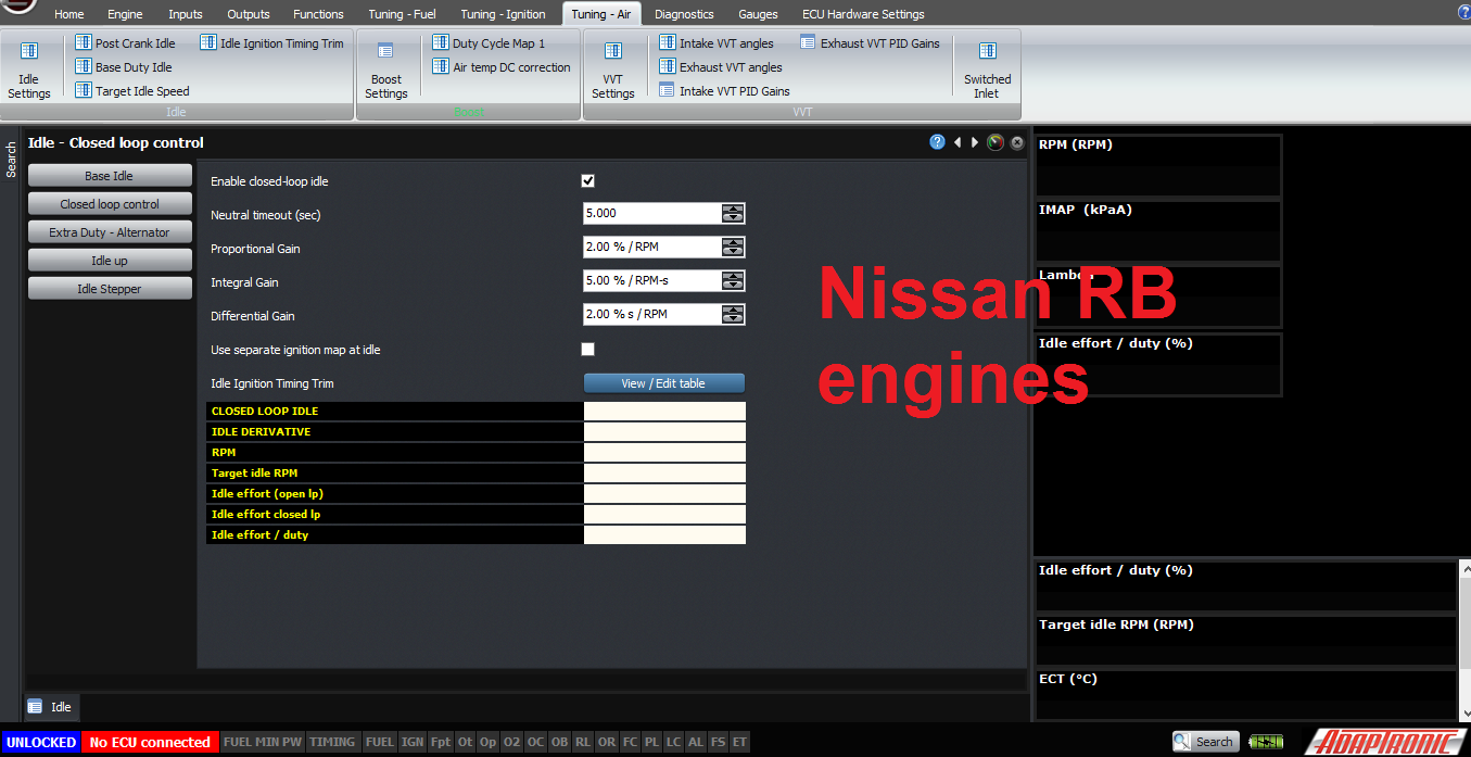
Now the last settings we need to set are the PID gains. I did a talk at PRI in 2016 about PID control and what they all mean, so I won’t describe PID here. Typical values I’ve used are 1, 2, 0.15 for PID on Mazda 13B engines, and about 2, 5, 2 on Nissan RB engines.
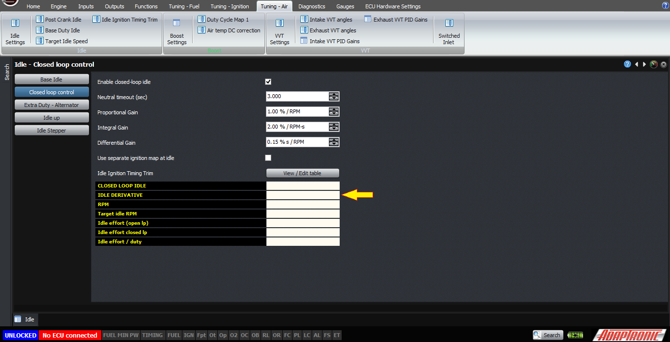
Now, the last thing I’d say is that the Modular ECU actually has 2 stages of closed loop idle control, and this is to help the engine come down to idle nicely. The first stage is activated as soon as the throttle is closed and the car is either in neutral/clutch is depressed, or the car is stationary, and this called “IDLE DERIVATIVE”. If you watch the flags on the closed loop idle screen, you’ll see this one come on first of all, basically as soon as you take your foot off the throttle on a free rev. In this condition, the ECU calculates only the derivative term, not the proportional and integral terms, of the PID controller. This helps the engine come back to idle gently. So if the engine wants to dip or stall when coming back to idle, and you’re sure that the fuel map is solid on the way back to idle, then increasing the differential gain can often help with this. The limit to how high you can increase it will be the fact that if you increase it too high, you’ll get a hunt at idle.
Try to get the majority of the control done with the proportional term, and use the differential term to stop the hunting as far as you can. Similarly increase the integral term as high as you can, but you’ll be limited by hunting that will occur if you increase it too high.
The last point to discuss is ignition timing at idle.
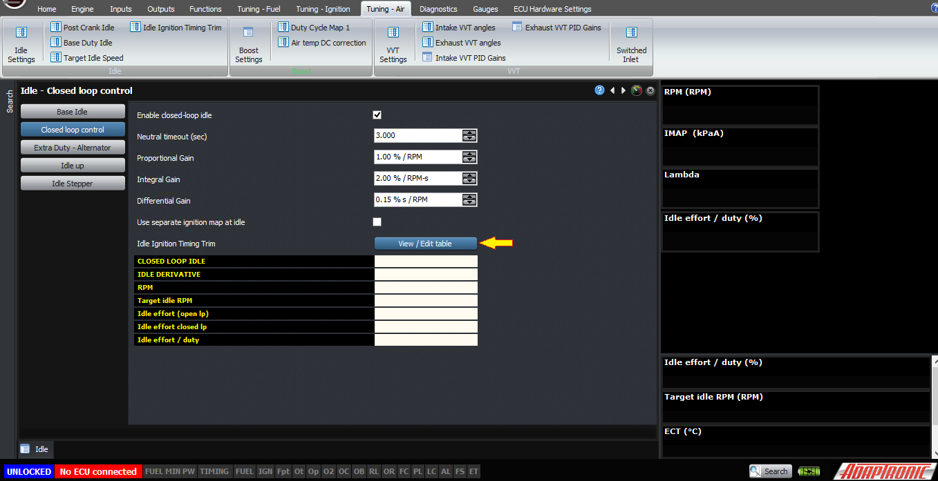
The default operation of the ECU is that it uses the main ignition map at the idle condition, just as at any other condition, however when the ECU is in closed loop idle, it can adjust the ignition timing to stabilise the idle speed.
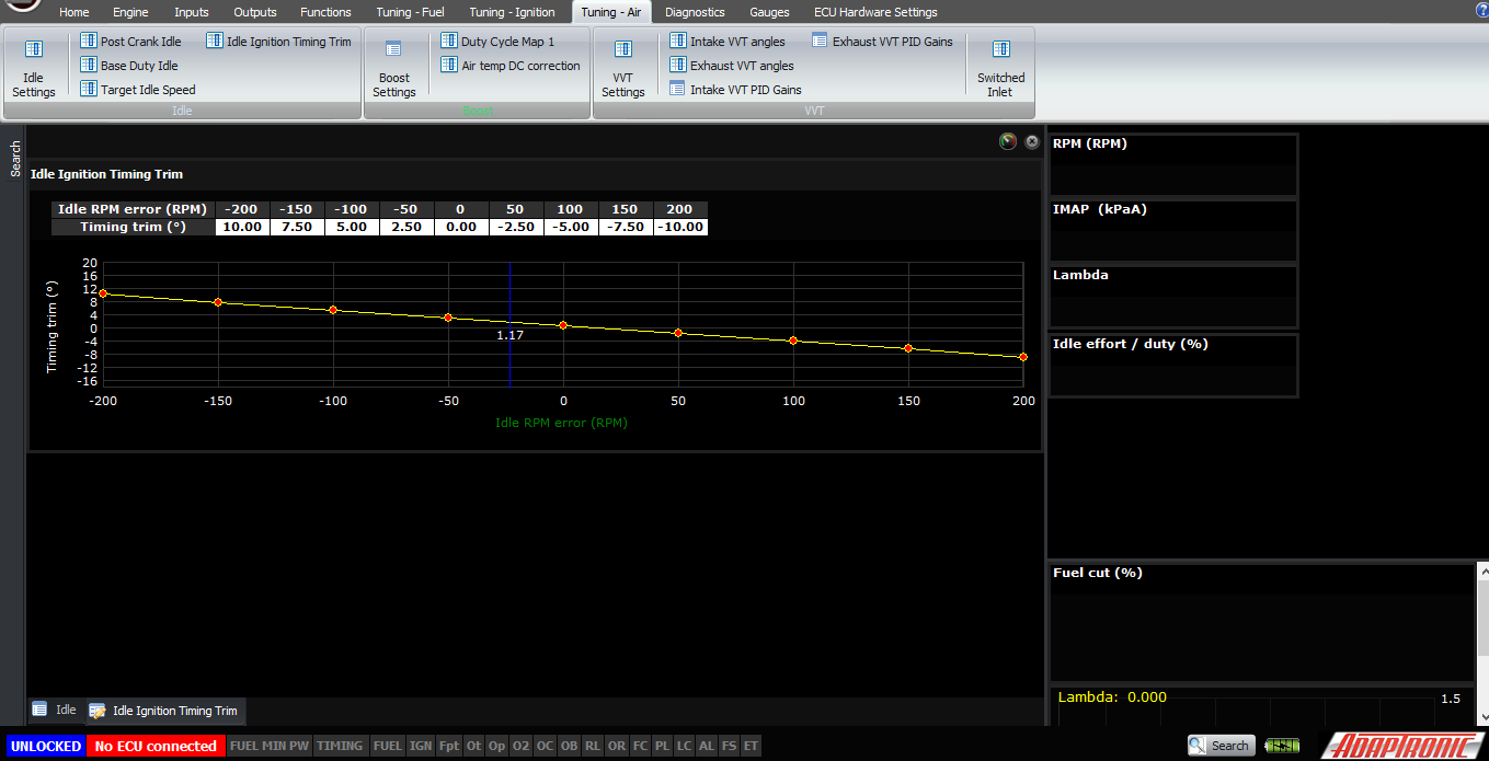
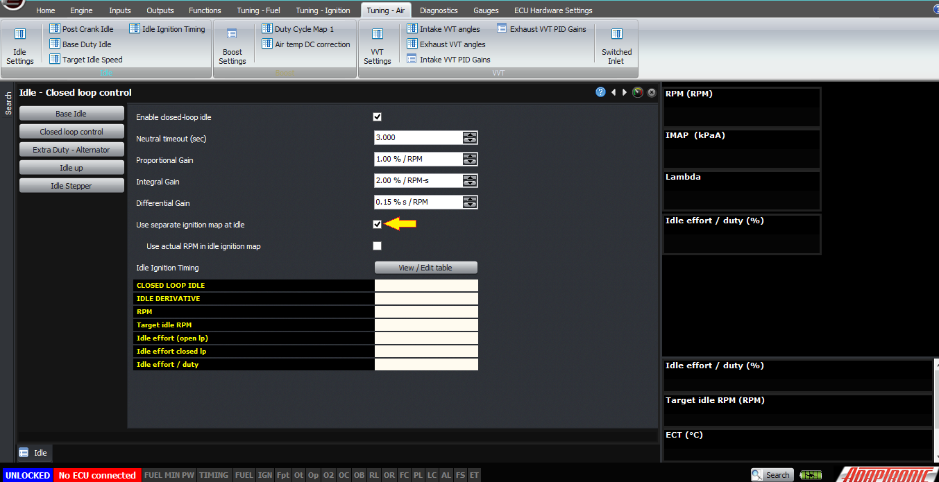
In this mode, the “Separate ignition timing table” is deselected, and the idle ignition table is a table of the ignition timing change as a function of the RPM error. RPM error is defined as the actual RPM minus the target, for example +200 means that the engine is 200 RPM above the target. So in general you’d have about +10° at -200 RPM, sliding down to 0° at 0 RPM, and -10° at +200 RPM. I have not found an engine yet whose idle smoothness did not benefit from ignition timing to correct the idle speed.
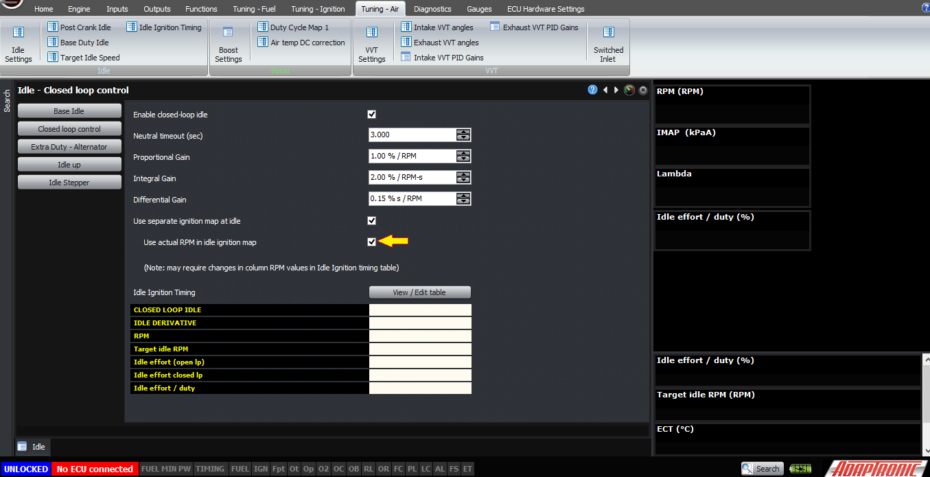
Another method, which has been requested by one of our customers, is to have a “separate ignition timing table”, in which case instead of making a correction to the ignition map, the ECU just looks at this separate ignition timing map when the ECU is in closed loop idle mode. In this case, you can choose whether the timing is dependent on the actual RPM, or the RPM error, and then the idle ignition timing table becomes the actual ignition timing.
Main problems that you might encounter with setting up closed loop idle are an idle hunt. In this case firstly you need to ensure that it is actually caused by the idle control – ie, if you disable the closed loop idle, the hunt goes away. If so, that means that one or more of your PID gains are too high, or possibly your D gain is too low. In this case, setting PID gains to zero means that you don’t have the problem, and with the PID gains you had, the problem occurs, so you can find a happy median between the two.
The other problem you might get is a dip or stall on return to idle. For this problem, it could be caused by several causes, the most likely being the fuel map being too lean on return to idle. However if you take a log and see the idle effort going lower than it should be and that’s what causing the dip, then it’s probably going into closed loop idle too early and you should try increasing the neutral timeout. The other common cause is if the ECU is going into closed loop idle when the engine is not idling, for example throttle-off while driving as I mentioned at the start of the article, in which case you need to check that your neutral/clutch inputs (if available) are working correctly and your vehicle speed input is also working correctly. This also should be evident in the log file, because if you graph RPM and idle effort, it should be obvious where you’re cruising, driving with your foot off the throttle, and the idle effort shouldn’t be changing during this time except for engine loads like air conditioner cycling and so on. In the log you can also look at the idle effort correction only due to the closed loop, which should definitely not be changing during this time.
Firstly, the ECU needs to know whether to go into closed loop idle or not. I’ve explained this in other places but for the sake of completeness I’ll include it here as well. It’s not enough to know that the throttle is closed, for the following reason. Imagine you’re in a situation where you’re in gear, for example at 2000 RPM, coming to a stop sign. Your foot is off the throttle. If the ECU went into closed loop idle in this circumstance, it would see that the engine is at 2000 RPM, which is too high compared to the target of 800 RPM, so it would reduce the idle effort. The RPM would remain unchanged so it would reduce the idle effort further. Eventually the idle effort would be all the way down to zero but the RPM would still be too high. Then as you put your foot on the clutch to stop at the stop sign, the engine stalls because the idle effort is zero where it might actually need 40% to idle properly.
Really the ECU needs to know if the engine is at the current RPM because it’s idling there, or because it’s being driven there by some outside force, like the wheels. Some cars are set up nicely from the factory and include a clutch switch and a neutral switch so that the ECU can tell if the engine is disconnected from the wheels, and will only go into closed loop idle if either the clutch is pressed or the gearbox is in neutral. Many other manufacturers don’t have these, but they have a vehicle speed input to the ECU, and the ECU will only go into closed loop idle if it detects the car is stationary.
The Modular ECU will go into closed loop in either of these conditions, but also the throttle must be closed (that is, the CLOSED THROTTLE flag on the TPS inputs page must be active), and either it must have fallen close to the target idle RPM, or if it hasn’t, then these conditions must have been met for a minimum amount of time, which is called the neutral timeout. The neutral timeout must be set so that the engine has enough time to fall from maximum RPM back to idle; otherwise the ECU will go into closed loop before the engine has got back down to idle, with a corresponding dip in the RPM, or possibly even a stall. A value of 5 seconds would be typical.
Let’s look at the settings required. Firstly we need to enable closed loop idle.
Secondly, we need to have our target idle speeds set in the target idle speed table. These can be varied against coolant temperature, and overridden by electrical loads, air conditioner activation and so on.
Next, we need to make sure that our closed loop conditions are configured correctly. If your car has neutral or clutch switches, then they can be connected to a digital input and configured as “clutch” type input. Functionally they mean the same thing, so they can usually be connected in parallel to the one input unless you have some other reason not to. If you don’t, then you will need to have a working wheel speed sensor input, and there’s another article explaining how to set this up.
Also please check that the closed throttle flag is working correctly. Sometimes aftermarket throttles get sticky and don’t always return to the same position, and sometimes there’s backlash between the throttle shaft and the sensor which means the TPS reading doesn’t reliably go back to zero when you close the throttle. Issues like this will cause problems setting up closed loop idle.
The neutral timeout has to be set, as I mentioned before, about 5 seconds is a good time.
Now the last settings we need to set are the PID gains. I did a talk at PRI in 2016 about PID control and what they all mean, so I won’t describe PID here. Typical values I’ve used are 1, 2, 0.15 for PID on Mazda 13B engines, and about 2, 5, 2 on Nissan RB engines.
Now, the last thing I’d say is that the Modular ECU actually has 2 stages of closed loop idle control, and this is to help the engine come down to idle nicely. The first stage is activated as soon as the throttle is closed and the car is either in neutral/clutch is depressed, or the car is stationary, and this called “IDLE DERIVATIVE”. If you watch the flags on the closed loop idle screen, you’ll see this one come on first of all, basically as soon as you take your foot off the throttle on a free rev. In this condition, the ECU calculates only the derivative term, not the proportional and integral terms, of the PID controller. This helps the engine come back to idle gently. So if the engine wants to dip or stall when coming back to idle, and you’re sure that the fuel map is solid on the way back to idle, then increasing the differential gain can often help with this. The limit to how high you can increase it will be the fact that if you increase it too high, you’ll get a hunt at idle.
Try to get the majority of the control done with the proportional term, and use the differential term to stop the hunting as far as you can. Similarly increase the integral term as high as you can, but you’ll be limited by hunting that will occur if you increase it too high.
The last point to discuss is ignition timing at idle.
The default operation of the ECU is that it uses the main ignition map at the idle condition, just as at any other condition, however when the ECU is in closed loop idle, it can adjust the ignition timing to stabilise the idle speed.
In this mode, the “Separate ignition timing table” is deselected, and the idle ignition table is a table of the ignition timing change as a function of the RPM error. RPM error is defined as the actual RPM minus the target, for example +200 means that the engine is 200 RPM above the target. So in general you’d have about +10° at -200 RPM, sliding down to 0° at 0 RPM, and -10° at +200 RPM. I have not found an engine yet whose idle smoothness did not benefit from ignition timing to correct the idle speed.
Another method, which has been requested by one of our customers, is to have a “separate ignition timing table”, in which case instead of making a correction to the ignition map, the ECU just looks at this separate ignition timing map when the ECU is in closed loop idle mode. In this case, you can choose whether the timing is dependent on the actual RPM, or the RPM error, and then the idle ignition timing table becomes the actual ignition timing.
Main problems that you might encounter with setting up closed loop idle are an idle hunt. In this case firstly you need to ensure that it is actually caused by the idle control – ie, if you disable the closed loop idle, the hunt goes away. If so, that means that one or more of your PID gains are too high, or possibly your D gain is too low. In this case, setting PID gains to zero means that you don’t have the problem, and with the PID gains you had, the problem occurs, so you can find a happy median between the two.
The other problem you might get is a dip or stall on return to idle. For this problem, it could be caused by several causes, the most likely being the fuel map being too lean on return to idle. However if you take a log and see the idle effort going lower than it should be and that’s what causing the dip, then it’s probably going into closed loop idle too early and you should try increasing the neutral timeout. The other common cause is if the ECU is going into closed loop idle when the engine is not idling, for example throttle-off while driving as I mentioned at the start of the article, in which case you need to check that your neutral/clutch inputs (if available) are working correctly and your vehicle speed input is also working correctly. This also should be evident in the log file, because if you graph RPM and idle effort, it should be obvious where you’re cruising, driving with your foot off the throttle, and the idle effort shouldn’t be changing during this time except for engine loads like air conditioner cycling and so on. In the log you can also look at the idle effort correction only due to the closed loop, which should definitely not be changing during this time.
Thank you and happy learning!
©2018 Adaptronic