Setting up Open Loop Idle Control on Modular ECUs

Hi all, in this video we’re going to discuss how to get the basic idle settings correct. I won’t be covering how to configure outputs for idle control and wire them up, because that’s done in a separate video.
Just like getting the fuel mixture right, getting idle control right starts off with having the basic map correct and then applying closed loop on top to do fine tuning. So let’s look at the basic factors that go into open loop idle.
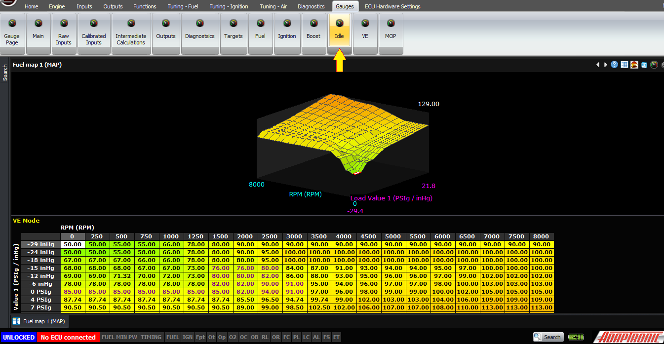
Firstly, let’s show where you can find the idle effort in the software. You can see it on the gauges window, next to RPM. The RPM field shows the current RPM, the target RPM and the idle effort (which could be duty cycle, number of steps or electronic throttle authority). You can also add it to the monitor window and it also appears in various idle setup pages.
Now, let’s look at the cranking condition. This is what happens when the engine is stopped, or when it hasn’t yet reached the cranking RPM threshold, for example 300 RPM. In this condition, the idle valve is held all the way open to make the engine easier to start. So the idle effort will be 100% in this condition.
Next, let’s consider what happens when the engine fires. After this happens, the ECU is in the running (as opposed to cranking) mode. In this mode, the ECU calculates the idle effort from the following factors:
- Base idle effort (which depends on coolant temperature)
- Post-crank idle effort (which depends on coolant temperature and time)
- Additional idle effort for electrical loads, air conditioner, thermofan, alternator and so on
- Closed loop control
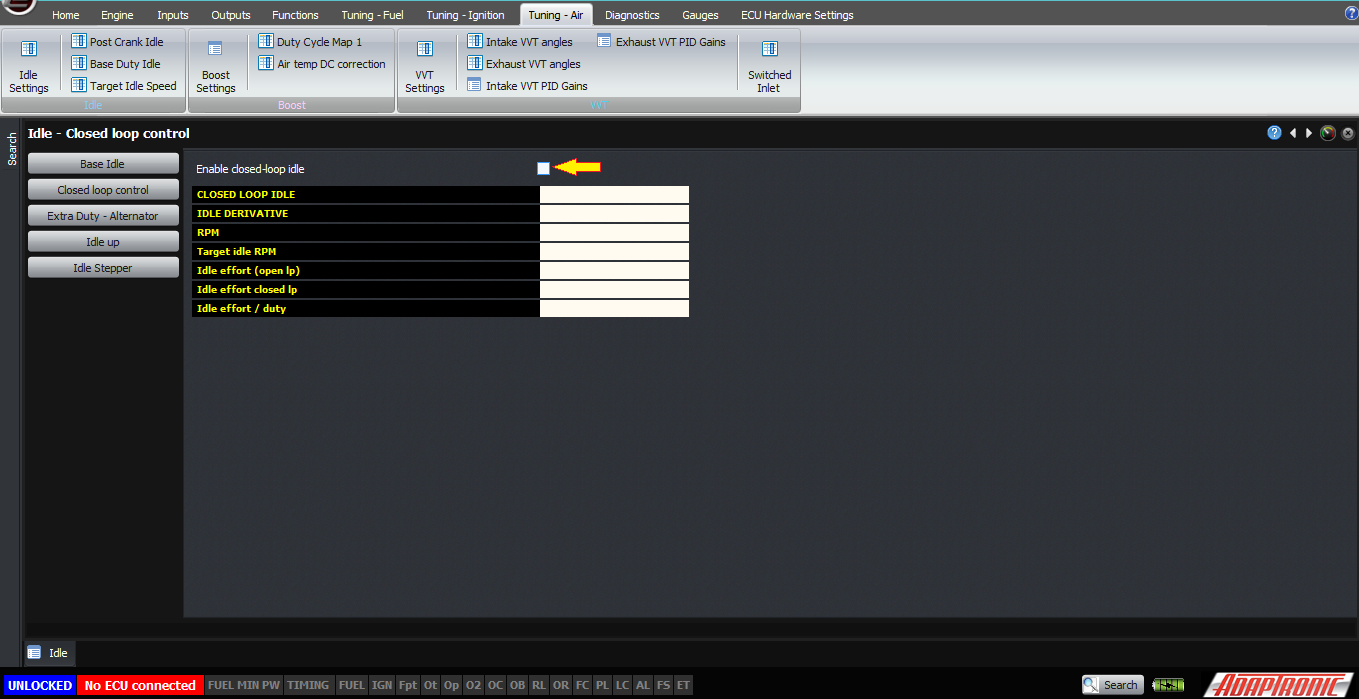
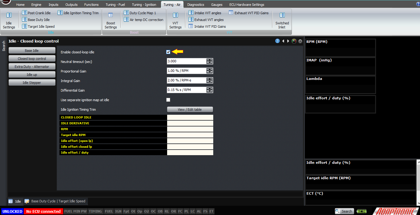
Initially, we’ll turn closed loop idle control off. This enables us to see what the actual settings are doing, as opposed to how well the ECU can correct it.
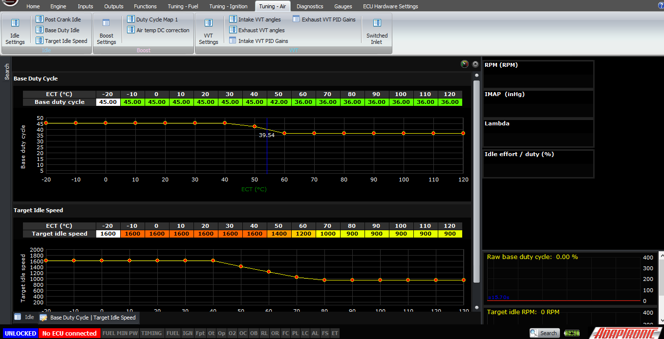
If we’re setting up the idle from scratch, we should also set all the idle-up values to zero, and start off with the base idle effort. This is best done with an engine starting from cold. Firstly, set the target idle speed against the coolant temperature; most port injected engines want to run higher RPM when they are cold to combat the fuel falling out of suspension at low temperatures.
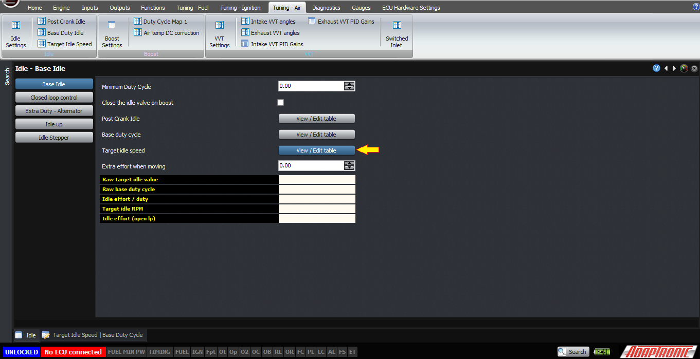
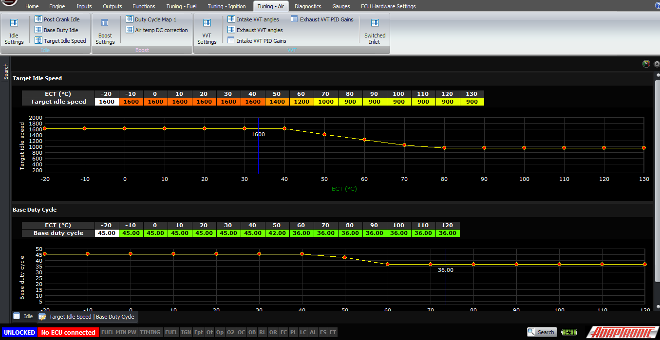
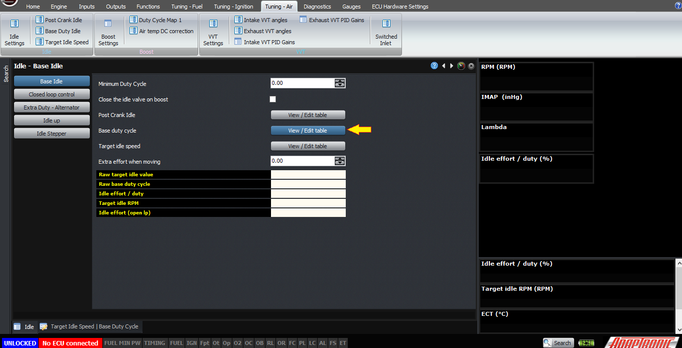
Secondly, as the engine heats up, adjust the base idle effort in the base duty cycle table against coolant temperature. Extrapolate past the ends as needed.
The other way to do this is to enable closed loop idle control, and then allow the closed loop function to settle on the target idle speed. Copy the final idle effort into the table at each temperature cell as it is reached.
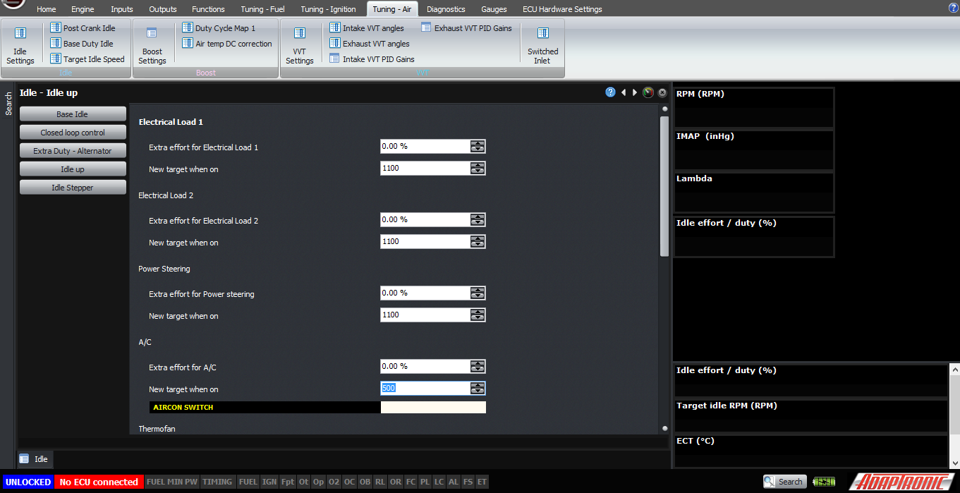
Next, you should set up the idle-up for loads. The procedure for this is to either adjust the additional efforts so that the target idle is still maintained when the load is applied, or to allow the closed loop to correct the idle effort, and take the difference between when the load is applied and when it is not and copy that into the additional idle effort. This is also described in the setup article for the air conditioner and the thermofan.
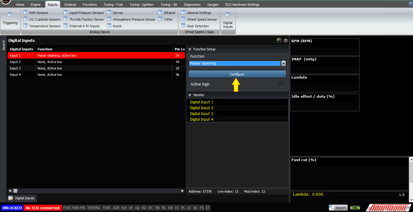
For idle loads which the ECU only knows about via external inputs, these also need to be wired in and configured. Generally these are switches which either pull to ground when they are activated, for example a power steering pressure switch. For this type of input, select a digital input that you’re not using, connect the switch to this input, and select the type as being “power steering” as an example.
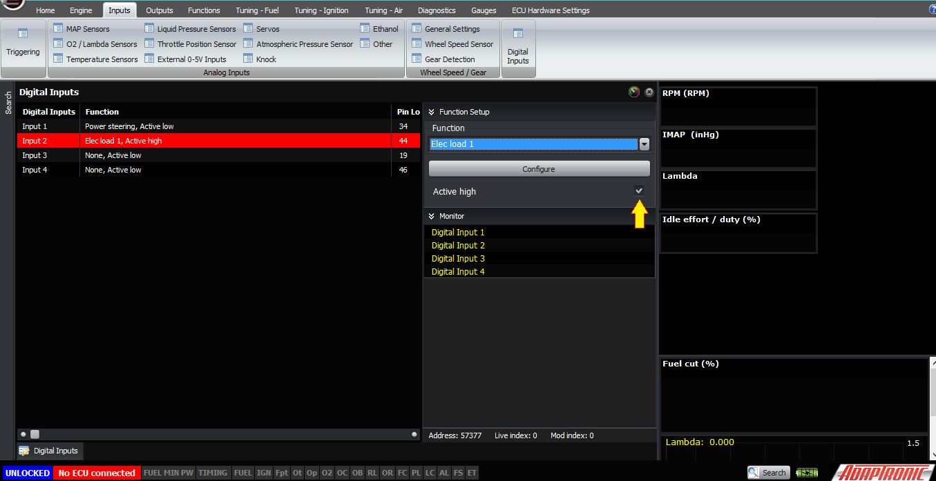
Another example is a headlight input. Normally this goes high to 12V when the headlights are on, but is shorted to ground when they are off. Again this should be connected to a digital input, and then the input should be selected as an electrical load, for example electrical load 1. But in this case because it’s driven high when it’s active, we must select “active high” in the digital input setting.
When any of the electrical inputs, power steering or air conditioner inputs are active, the ECU will increase the target idle RPM to the “new target when on” setting in the idle-up page. If this target is below the target idle speed in the target idle speed table, it will use the target idle speed from the table instead (ie, it uses the maximum of the target idle speed from the table, and the “new target” of any activated input).
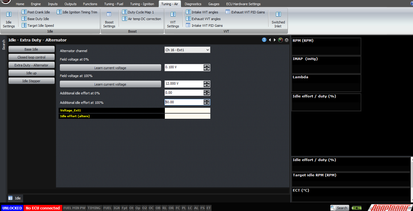
The “extra duty – alternator” function is for cars where the ECU is able to see the alternator field current, for example if the regulator is built into the ECU rather than the alternator itself. This is the case with the NB and later MX5 / Miata, the RX8, 86/FRS/BRZ and the Dodge SRT4 and probably many others. In this case you can select an input channel for the field current, enter a maximum and minimum voltage for that input corresponding to the min and maximum values that you will see, and minimum / maximum idle efforts for these conditions. Normally the minimum idle effort would be zero. The ECU will scale the idle effort linearly between these two and in practice it works really well; much better than with digital inputs to select whether different functions on the car are turned on or not.
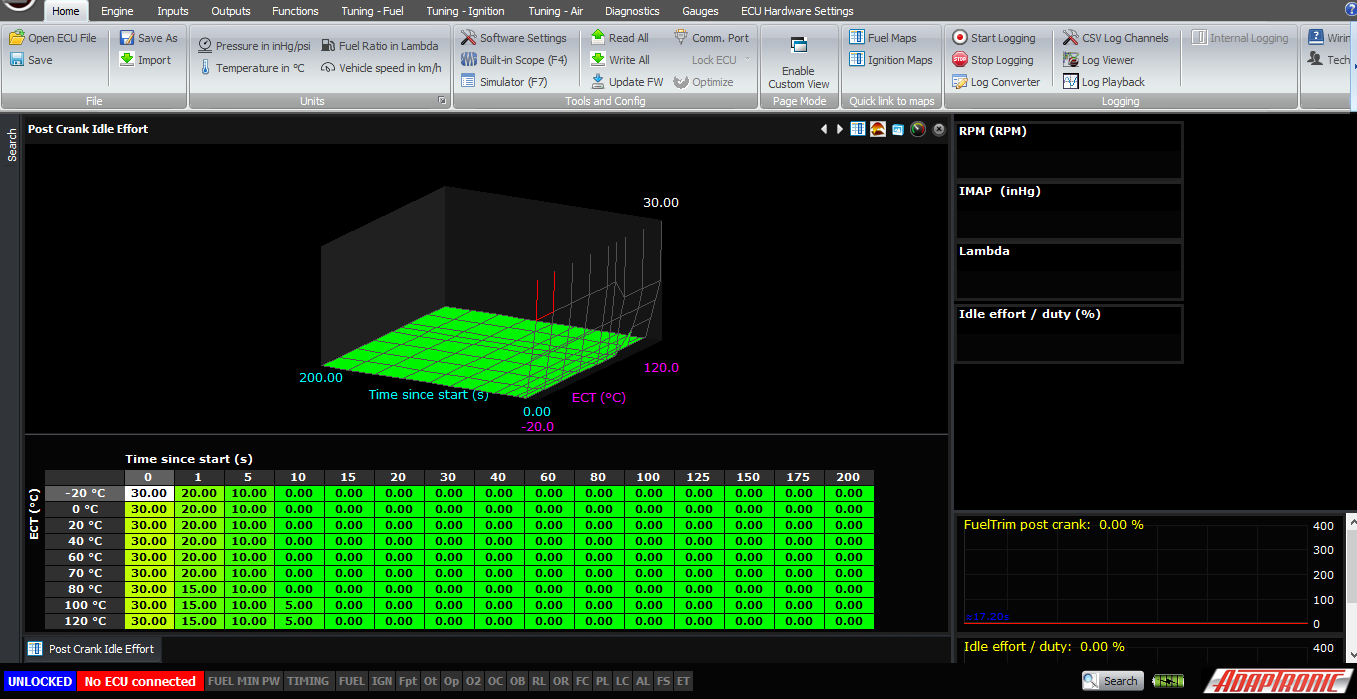
The final function I wanted to talk about is the post-crank idle-up. This is a table with coolant temperature on one axis and time on the other. Time=0 is the time where the engine actually first fires, and for example 10 represents 10 seconds after the engine has started. This table enables you to program in a post-crank flare to clear the engine out, or save it from a stall or whatever is desired on that particular engine. Note that it will be interpolated between these points, and the maximium time you can have post-crank idle for is 300 seconds or 5 minutes (in practice, if you need it that long you’re probably doing something wrong). Note that whenever the interpolated value from this table (ie, the extra idle effort to add due to the post-crank amount) is greater than 1%, the ECU will not go into closed loop idle. Obviously during this post-crank flare, it’s going to be above the target idle speed, and that’s where you want it, so going into closed loop in this condition is not an option. So the ECU will stay in open loop until the correction is down to less than 1%.
The only thing I’ll say about setting up the post-crank idle effort is that sometimes if an engine doesn’t want to rev up nicely post crank, it’s not because of the idle effort but it’s instead because of poor fuelling. So if it doesn’t seem happy and you want it to rev higher or clear itself up, then you should check the post-crank enrichment first – try 10% more or 10% less in this table first to see if it makes a difference.
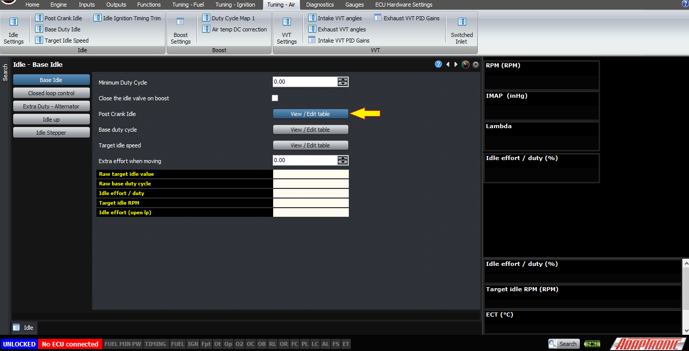
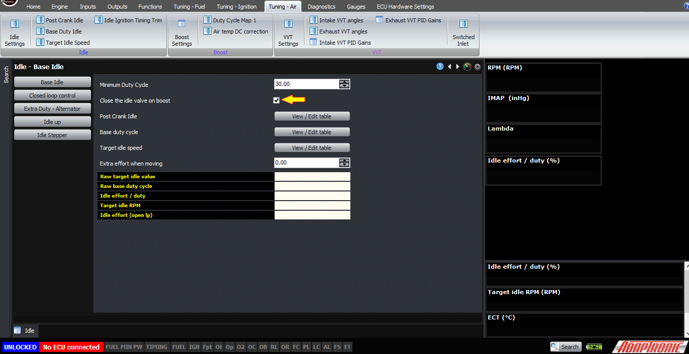
Two final settings – one is the minimum duty cycle. In most cases you can set this to zero. In some cases, setting it just below the minimum that you encounter with a hot engine and no electrical loads can help with idle stability. And on some idle valves, below a certain duty cycle they actually start admitting more air, so you need to stay away from that end of the scale because non-monotonic actuators make Andy cry.
The final setting is “close idle on boost”. In most turbocharged applications, the air for the idle control valve will be taken from just before the throttle body, so it really acts as an idle bypass. However in some cars, even in some OEM installations like some Toyota 1JZ cars, the idle motor actually gets its air source from an unpressurised source. So if the idle valve remains open when the engine is on boost, air leaks back through the idle valve to the air filter and creates a boost leak. If you enable this setting, the idle valve will be closed when the engine is on boost (by closed we mean set to the minimum duty cycle).
In a separate article, we’ll talk about closed loop idle control.
Thank you and happy learning!
©2018 Adaptronic