Twin Turbo Control on Modular ECU

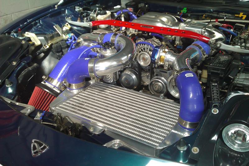
In the early to late 1990s, it was common for some halo cars to run twin turbocharger systems. We saw this with the Nissan GTR from the R32 to the R34, the Mazda RX7 FD and the Supra JZA80. Broadly speaking, there are two types of twin turbo systems; the parallel systems as on the RB26 Nissan engines, and the sequential twin turbos as on on the RX7 and the Supra. This article will only discuss the sequential twin turbo system on the RX7 FD.

Parallel twin turbo systems
Sequential twin turbo systems
The two turbochargers are both the same size on the standard RX7, however at low RPM, only one turbo is active. At high RPM, or the full-power condition, both turbochargers are active. This allows rapid spooling of the small turbo at low RPM, while not being limited by its restriction at high RPM, because at high RPM you have two of them working and therefore double the flow capacity.
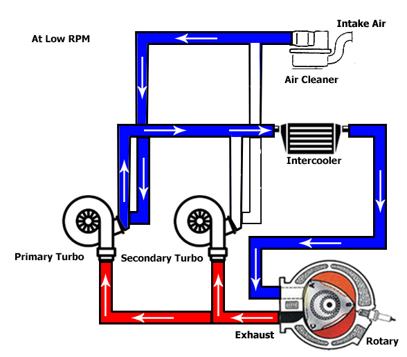

When only the primary turbo is running, all the engine exhaust goes through either the primary turbine, or bypasses the turbine through the wastegate. The compressed air from the primary turbo is fed into the intercooler after which it goes up to the throttle and intake manifold. Note that in this case, the compressor exit from the secondary turbo has to be blocked off, otherwise the compressed air from the primary turbo would feed back through it, which would mean it wouldn’t produce any boost.

So in this condition, the inlet charge control flap is closed, and the turbo control valve is also closed, to prevent exhaust going through the secondary turbine.
At high RPM, we must open both of these flaps, to allow the second turbo to share in the exhaust from the engine, and to contribute compressed air into the inlet. So in this condition, both flaps are open.
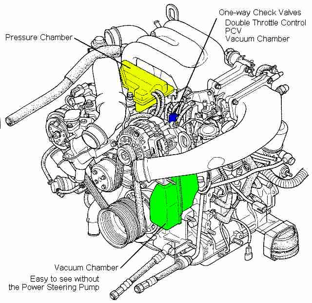
In the RX7 system, there are two chambers which check valves going to the inlet manifold. One is pressurised with boost air, and the other stores vacuum. The solenoids that control these flaps are configured so that each flap actually has two solenoids, that each connect either boost or vacuum to one side of a servo diaphragm. Therefore in one position, one side of the diaphragm has boost and the other has vacuum, and in the other position the two are swapped around. Therefore it is necessary for both solenoids to be working, on all the flaps which need to be controlled (both the intake and the exhaust, and there is a second one in the exhaust I will describe later), and the hoses all need to go to the correct locations.
The tricky part comes with the transition. You can imagine that if you’ve just been boosting hard on the first turbo, and you engage the second turbo straight away by moving both the exhaust and inlet flaps at once, then you’re going to get a dose of turbo lag until the second turbo comes up to speed so it’s producing the same boost as the primary turbo. This gets worse the more boost you have on the primary turbo, for two reasons. The first reason is that the first turbo loses boost, because you’re diverting exhaust to the secondary turbo to spool it up. The second reason is that the secondary turbo actually needs to spin up to a higher speed to match the boost of the primary turbo.
Mazda weren’t silly so they added in what they call a “precontrol valve”. This allows a small amount of air to be diverted through the secondary turbine. It does cause a drop in boost of the primary turbo but it’s not too extreme. Secondly, there is a blow-off valve (charge relief valve) on the outlet of the secondary turbo, which is under ECU control. As you’d know it’s possible to overspeed a turbo by not “loading” it, ie letting it just breathe into the atmosphere and not deliver any boost. So what is done is for a very short amount of time, we can open this precontrol valve, and the charge relief valve at the same time, to get the secondary turbo to spin up. Once it’s spun up, we can switch over the intake flap and main exhaust flap to allow both turbos to do the job.
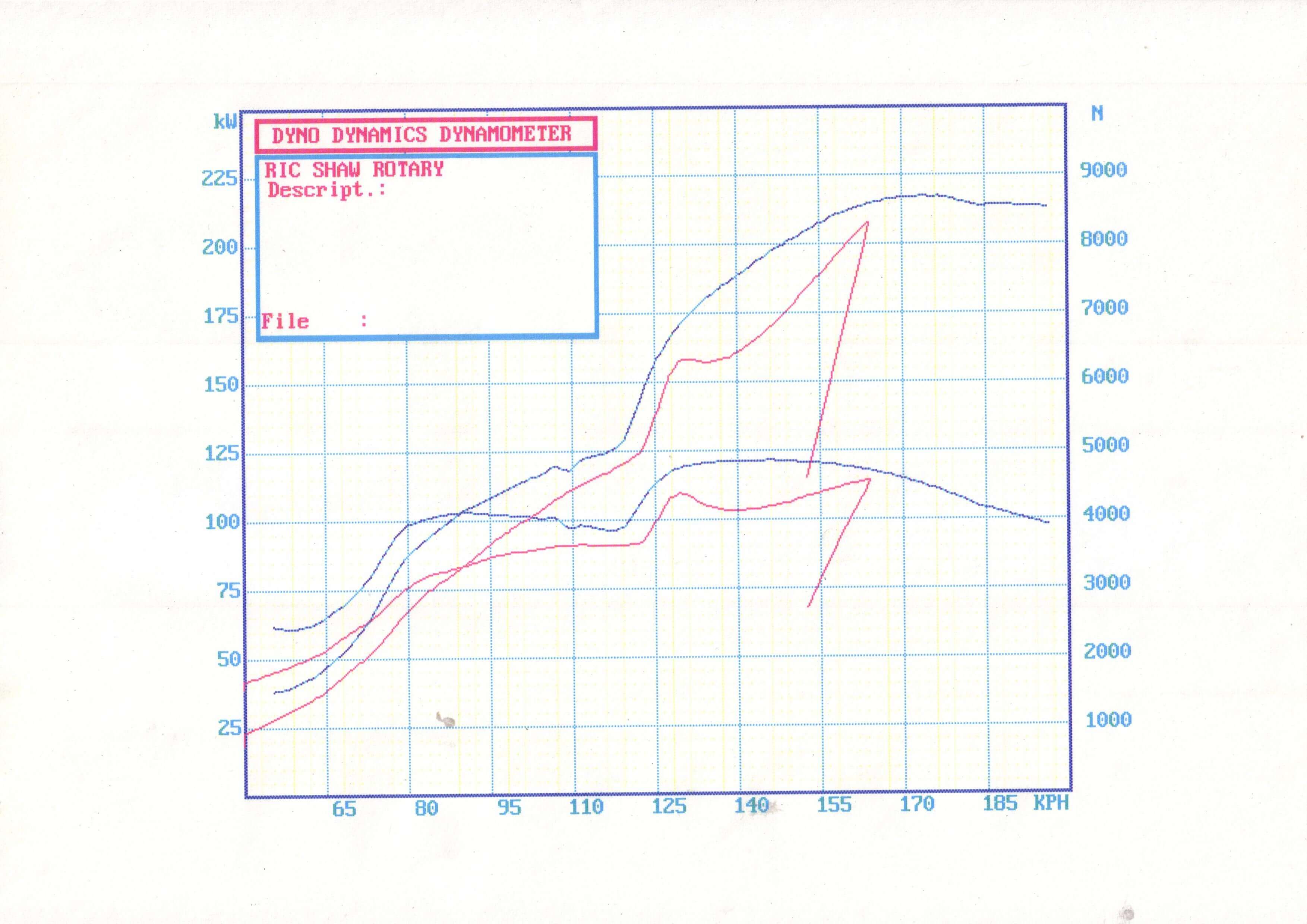
Dyno graph with PWM precontrol valve

Sample dynograph
How long we need to spin up the second turbo for depends really on the turbo inertia, and that determines the time. So doing this over an RPM window won’t be very useful because that RPM window will correspond to a different time in different gears, boosts and so on. So instead we actually tell the ECU the time for which we want to spin up the second turbo, and the RPM we want to finish by. The ECU looks at the current rate of change of RPM and the current RPM to work out when it needs to start the precontrol period. Previously we have used a short period and just turned on the precontrol output hard, but it turns out that starting earlier and pulse width modulating the precontrol output period tends to keep the boost up and smooths out the power curve.
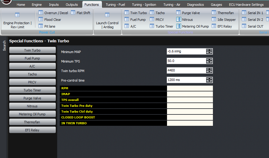
In terms of the settings, the ECU needs a minimum MAP and a minimum TPS to activate the twin turbo function. Then there is the RPM to enable the secondary turbo, and the pre-control duration as described just before.
The values we have used are 4400 RPM and 1200 ms (or 1.2 seconds).
This feature is a bit redundant now since turbo technology has come such a long way, and there are many single turbochargers that behave as well as the factory twins, but many series 8s are still running the factory twins so this function is needed.
Lastly, we need to talk about the outputs. The easiest way to do this is with a plug and play ECU. But if you’re wiring in, then please observe the following:
1) The charge control valve and the turbo control valve need to be opposite polarity. Therefore enable one in the software as Twin Turbo, ann the other as Twin Turbo, inverted
2) The precontrol output needs to be inverted, and as I said above, making it PWM even at say 25 Hz does help with the power curve.
3) The charge relief valve can be connected in parallel with the twin turbo output control
Thank you!
©2018 Adaptronic