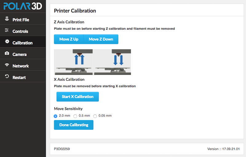
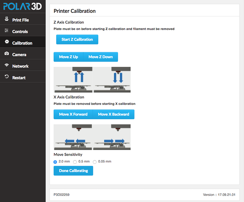
Figure 6.4: Polar3D 2.0 or 2.5 printer Calibration screen

Go to the printer’s local web interface and click the “Calibration” tab to get to the “Calibration” screen; see Figure 6.4.
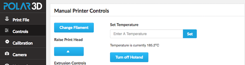
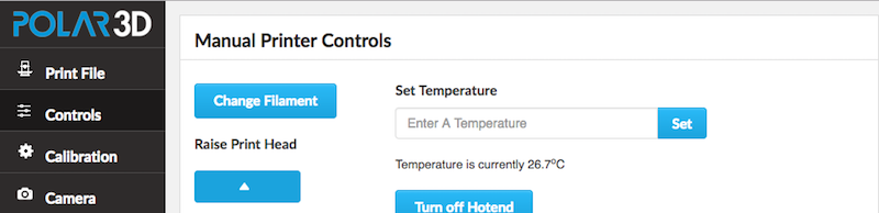
If filament is currently loaded onto the printer, you will need to unload the filament: click the “Controls” tab on the left menu to get to the “Manual Printer Controls” screen, and there click the “Change Filament” button; see Figure 6.5.
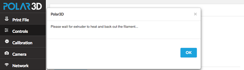
A screen will pop-up explaining that the printer needs to heat up the extruder in order to change the filament; click “OK” at this confirmation screen, (Figure 6.6).
Once the temperature reaches 185° C, see Figure 6.7, (and if you are listening carefully, you should also hear the noise of the printer filament drive gear running to back out the filament from the extruder), pull the filament the rest of the way out of the extruder. (Note that the extruder temperature will not stay at 185° C: as soon as the printer has backed out the filament, it will turn the extruder heater off.)
Having unloaded any filament, you are now ready to proceed with calibration, so click the “Calibration” tab on the left-hand menu to return to the “Calibration” screen.
If you wish to perform z calibration, check that the build plate is installed on the printer. Then on the “Calibration” screen (refer to Figure 6.4), click the “Start Z Calibration” button.
Clicking the “Start Z Calibration” button will bring up the screen shown in Figure 6.8; click the “Ok” button to dismiss the screen.
Now check the position of the extruder nozzle end relative to the build plate. You want to be able to just slide a sheet of paper between the two, feeling resistance. If the paper slides easily, not touching the extruder nozzle end at all, you need to lower the extruder nozzle: click the “Move Z Down” button. If a sheet of paper cannot slide underneath the nozzle end, if the nozzle end is touching the build plate, you need to raise the extruder nozzle: click the “Move Z Up” button.
Once you are finished with any moves of the nozzle up or down, click the “Done Calibrating” button; see Figure 6.9.
Clicking “Done Calibrating” will bring up the screen shown in Figure 6.10; click the “Ok” button to dismiss the screen.
If you now wish to perform x calibration, you must remove the build plate from the printer (in order to be able to visually compare the locations of the extruder nozzle and the build plate shuttle’s drive gear bearing). If you just finished completing z calibration, the print head will be lowered to the build plate and you will not have free room to remove the build plate; in this case, click the “Controls” tab on the left-hand menu to go to the “Manual Printer Controls” screen and at that screen click the “Raise Print Head” (up arrow) button a few times; see Figure 6.11. Once you have room to do so, remove the build plate from the printer.
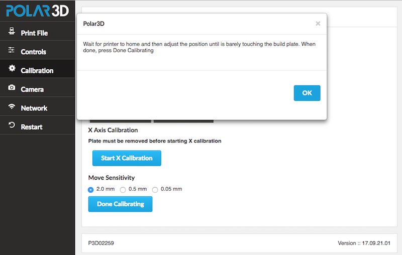
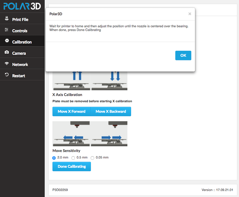
With the build plate removed from the printer, you are now ready to begin x calibration, click the “Calibration” tab on the left-hand menu to return to the “Calibration” screen. On the “Calibration” screen (refer to Figure 6.4), click the “Start X Calibration” button. This will bring up the screen shown in Figure 6.12; click the “Ok” button to dismiss the screen.
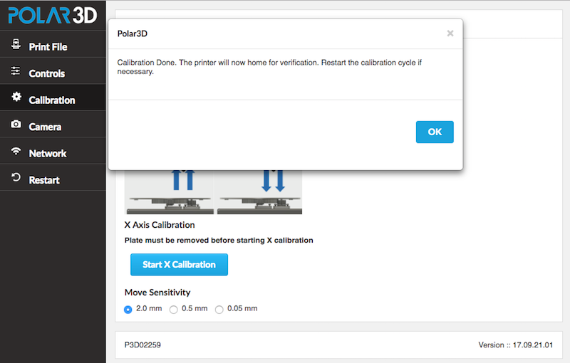
Compare the position of the center of the extruder nozzle to the center of the build plate shuttle’s drive gear bearing. If necessary, click the “Move X Forward” or “Move X Backward” button to adjust the location of the build plate shuttle to line up its drive gear bearing directly underneath the extruder nozzle. When done, click the “Done Calibrating” button; see Figure 6.13.
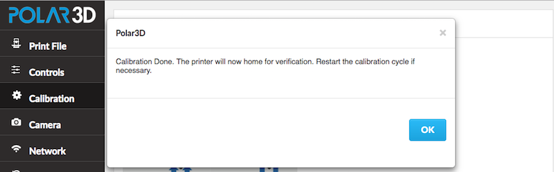
Clicking “Done Calibrating” will bring up the screen shown in Figure 6.14; click the “Ok” button to dismiss the screen.
You’re done with z and x calibration! See the discussion of consistent levelness of the build plate (item 3 in Section 6.5) if you still seem to have a bit of miscalibration.