DXF import options.
![]()
![]() Note: DXF files are unit-less, and objects can be assigned any scale. It is important that you are aware of the imported DXF file units & scale. ACE needs to know what physical unit and scale to use for 1 DXF unit. For example:
Note: DXF files are unit-less, and objects can be assigned any scale. It is important that you are aware of the imported DXF file units & scale. ACE needs to know what physical unit and scale to use for 1 DXF unit. For example:
If a DXF file was designed in inches, set 1 DXF UNIT to "Inch" with a scale of "1.0"
If a DXF file was designed in Microns with a 10X scale, set 1 DXF UNIT to "micron" with a scale of "10.0"
![]() Note: If you have selected potentially wrong DXF units, ACE will issue a warning and make a suggestion.
Note: If you have selected potentially wrong DXF units, ACE will issue a warning and make a suggestion.
![]() Note: When translating from DXF to Gerber, four additional option pages (Layer, Block,Text, Merge) are activated. For all other formats these option pages are hidden.
Note: When translating from DXF to Gerber, four additional option pages (Layer, Block,Text, Merge) are activated. For all other formats these option pages are hidden.
![]() Note: Use Polygon De-Embedding automatically solves the polygon-inside-of-polygon problem found in many mask designs. The polygon-inside-of-polygon is often the hardest mistake to catch and many times there are 1000s of overlapping polygons on a layer; it's almost impossible to visually determine the polarity for each. A mask operator can sometimes take hours attempting to repair or redraw the data so that re-entrant polygons are created with voids or has to break up the polygons into slices.
Note: Use Polygon De-Embedding automatically solves the polygon-inside-of-polygon problem found in many mask designs. The polygon-inside-of-polygon is often the hardest mistake to catch and many times there are 1000s of overlapping polygons on a layer; it's almost impossible to visually determine the polarity for each. A mask operator can sometimes take hours attempting to repair or redraw the data so that re-entrant polygons are created with voids or has to break up the polygons into slices.
![]() Note: If your DXF file contains MInserts (multi-Inserts), ACE can output Step/Repeat data (for Exported Gerbers), or Arrayed Cells (for Exported GDSII & OASIS) - which drastically reduces file size and processing time.
Note: If your DXF file contains MInserts (multi-Inserts), ACE can output Step/Repeat data (for Exported Gerbers), or Arrayed Cells (for Exported GDSII & OASIS) - which drastically reduces file size and processing time.
Import DXF Units (Located on ACE main page):
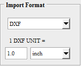
1 DXF UNIT= Units/Scale:
|
DXF files are unit-less, so it is vital to specify the proposed units & scale for 1 DXF physical unit. Choose from Micron, Inch, Millimeter, Centimeter, and more. The Logical DXF unit size will be defined by defined by DXF Units * Scale |
Import DXF Layers:
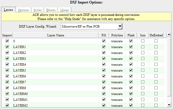
![]() Note: The DXF Layer Config Wizard is a preset feature used to optimize your DXF layer settings (such as Fill, Polyline End cap, Flash) for the most common type of design your translating. Choose whatever description best describes the type of DXF design. The feature is optional.
Note: The DXF Layer Config Wizard is a preset feature used to optimize your DXF layer settings (such as Fill, Polyline End cap, Flash) for the most common type of design your translating. Choose whatever description best describes the type of DXF design. The feature is optional.
Import:
|
If "checked" this layer will be imported. If "unchecked", this layer will be omitted. |
DXF Layer Name:
|
The DXF layer name. This is merely for reference, and cannot be changed. |
Fill:
|
If "checked", all closed boundaries for this layer will become filled polygons. If "unchecked", all closed boundaries for this layer will be open paths, and use the Default Line Width. |
Polyline:
|
This setting controls the End caps for open-polylines with width on this layer. Truncate: Square End cap, no extension. Extend: Square End cap, 1/2 width extension. Round: Round End cap, 1/2 width extension. |
Flash:
|
If "checked", all Rectangles and Circles on this layer, which are smaller than the setting "Flash Circle/Rects Less Than", will be converted to Gerber Flashes. (For Gerber Export Only) |
Join:
|
Adjacent lines and arcs that form a boundary are automatically joined. This is very useful for creating polygons from sperate lines and arcs entities in the DXF file. |
DeEmbed: |
Automatically solves the polygon-inside-of-polygon polarity problem. Closed boundaries (on the same layer) found completely inside another boundary will be made clear (or dark). Due to its complexity, this feature may be time consuming during the conversion. |
Import DXF Options:
Respect ByBlock/ByLayer:
|
Block entities that are on designed layer '0', will be changed to the layer of the respective insert. |
Hatch Mode:
|
Controls the inclusion or exclusion of Hatches. Include All Hatches: Hatches will be processed. Ignore All Hatches: Hatches will be omitted. Import Hatches Only: Hatches will be processed. Construction lines, arcs, circles etc will be ignored. |
Arc Deviation: |
The maximum error allowed when calculating points on an arc. This feature allows designs with large and small radius arcs to equally maintain high-resolution and quality. The smaller the Arc Deviation the more accurate your final arcs will become - however exported file sizes may become larger. |
Default Line Width:
|
All 0-width DXF entities (such as lines, arcs, 0-width polylines) will be assigned this physical width (if they do not form a filled-polygon). |
Flash Circle/Rects Less Than:
|
All detected Circles & Rectangle shapes will only be flashed in their bounding width & length are less than this value. (For Export Gerber Only) |
![]() Note: All Hatches are treated as solid hatches. Only the outlines are processed, while patterns (if any) are ignored.
Note: All Hatches are treated as solid hatches. Only the outlines are processed, while patterns (if any) are ignored.
![]() Note: Hatch Mode "Import Hatches Only" is a useful option when a DXF files contains both solid hatches depicting the desired image, and construction geometries such as lines, arcs, & circles used to generate the hatch. These construction geometries cause overlapping geometries during the translation, and confuse the De-Embedding Engine.
Note: Hatch Mode "Import Hatches Only" is a useful option when a DXF files contains both solid hatches depicting the desired image, and construction geometries such as lines, arcs, & circles used to generate the hatch. These construction geometries cause overlapping geometries during the translation, and confuse the De-Embedding Engine.
![]() Note: If your dxf contains hatches with "Holes" we highly recommended that you also check the DXF Import Layer Option "DeEmbed" for the all layers containing the hatch
Note: If your dxf contains hatches with "Holes" we highly recommended that you also check the DXF Import Layer Option "DeEmbed" for the all layers containing the hatch
Import DXF Styles:
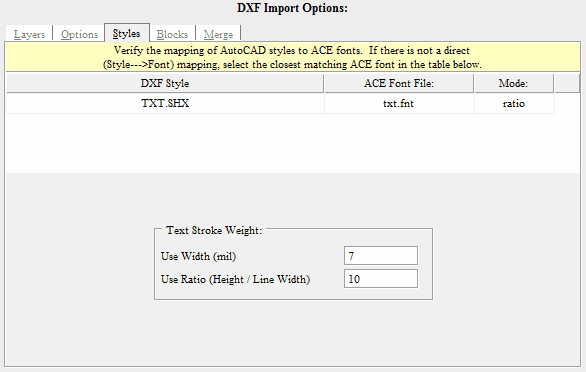
DXF Style:
|
The DXF style name. This is merely for reference, and cannot be changed. |
ACE Font File:
|
Choose which Pre-Compiled ACE Font File to use from the pull-down. All ACE Font files are derived from TrueType fonts respectively. You may compile a ACE Font file from any TrueType font |
Default Text Style:
|
Assign the default ACE Font File to use when an associated DXF font file cannot not be determined or located. |
Text Line Width/Fill Method:
|
The setting controls the DXF Text output options: Polygon: All Text will be filled as polygons. Their widths are already determined in the ACE font file itself. Stroke: Determine a standard line width to be used for all DXF text. Ratio: The text line width will be determined by a ratio of the text height divided by your supplied value. |
Import DXF Blocks:
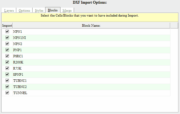
Import:
|
If "checked" this block will be imported. If "unchecked", this block will be omitted. |
DXF Block Name:
|
The DXF block name. This is merely for reference, and cannot be changed. |
Import DXF Merge:
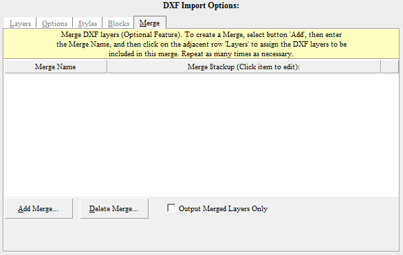
Merge Name:
|
The output name to be used for the merged layer. |
Merge Stackup:
|
Select all DXF Layers that will be included in this merged layer. |
New:
|
Create a new "empty" merge layer. |
Delete:
|
Delete an existing merge layer. |
Output Merged Layers Only:
|
Do not output any individual DXF layers, only the merged layers will be created. |