Setting up the AEM CD7 Dash with the Adaptronic Modular ECU

The AEM CD7 dash is one of the many
full colour TFT dashes on the market. It has built in support
for many aftermarket ECUs and a fully configurable CAN system.
This article shows two ways that it can be used.
In both, we will just use the CAN1 connection on the dash. The dash actually has 2 CAN busses, but we will just use the first one in this example.
In terms of physical connection, all the pins we need are found on the 4 pin DTM connector. The colours are as follows:
In both, we will just use the CAN1 connection on the dash. The dash actually has 2 CAN busses, but we will just use the first one in this example.
In terms of physical connection, all the pins we need are found on the 4 pin DTM connector. The colours are as follows:
| Pin and Colour |
AEM Name |
Our connection |
| 1 - White |
CAN 1+ |
CAN H – J2-15 on M2000 / M6000 |
| 2 – Green |
CAN 1- |
CAN L – J2-23 on M2000 / M6000 |
| 3 – Red |
Switched Power |
Ignition switched power - J2-7 on M2000 / M6000 |
| 4 – Black |
Power ground |
Power ground – J2-8 on M2000 / M6000 |
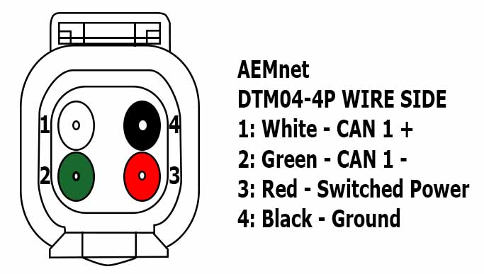
Note that here, the standard red/black are used for power and ground, and white/green are the CAN pair, unlike the Racepak where they use red/green for power and ground, and white/black for the CAN pair. The best thing about standards is that there are so many to choose from.
Using the Haltech V2 Protocol
The first method is to use the Haltech V2 protocol. The Adaptronic Modular ECUs can emulate the Haltech V2 protocol which allows it to be used with any dash that supports the Haltech, with the exception of the Haltech IQ3 simplicita, but if you want to use that dash, then please read the article or watch the video on how to use the Racepak dashes.
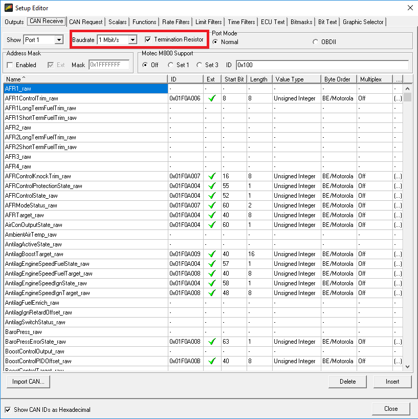
Firstly, the Haltech protocol specifies a bit rate of 1 Mbps, but both the ECU and the dash allow you to choose different bit rates. So to be correct, the ECU should be set to 1 Mbps, and the termination should be set to “on”. If you’re using the secondary CAN port on a Modular ECU that supports a second CAN port, the termination is always on and can’t be disabled.
Secondly, the dash must be configured using the AEM Dash Design software. To do this, load your dash configuration and then go to Setup -> Display.
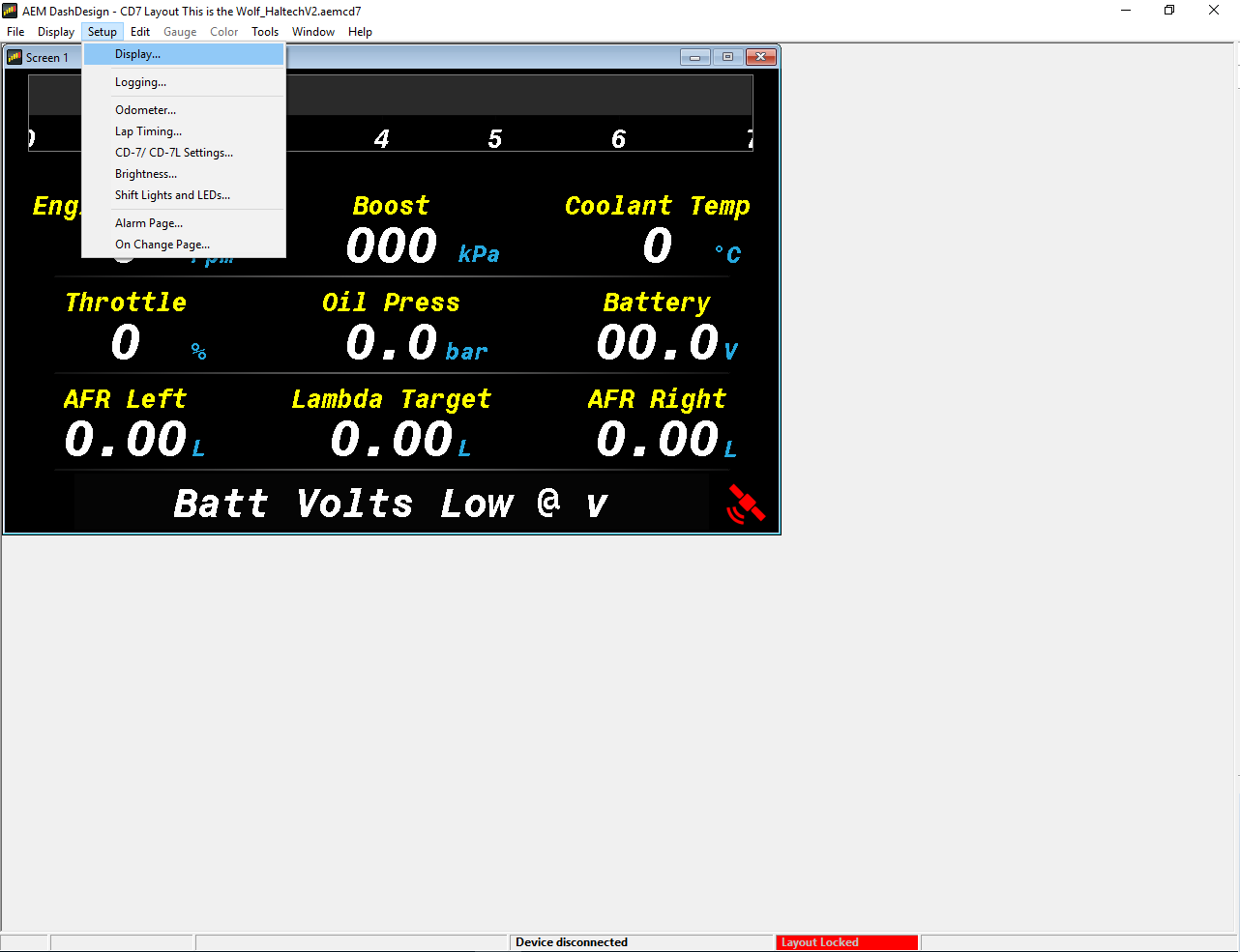
In the Setup editor, go to CAN Receive.
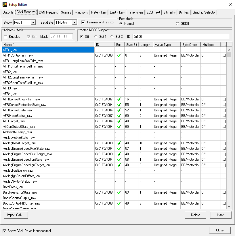
Select the following settings:
- Choose port 1 (because we are connecting via the CAN1 port on the 4-pin DTM connector)
- Baudrate = 1 Mbps (default is 500 kbps)
- Termination resistor = checked / enabled
- Port mode = normal
- Motec M800 support =off
Then select the “Import CAN…” button
Select the Haltech V2 AEMCAN template:

And select “replace” when it asks you if you want to override the new channels.
Send this to the dash using the “Upload to Display” or Ctrl+U and the two devices will now talk to eachother.
The following lists the Haltech channels as implemented in Modular firmware 0.145 and notes for them. Note that the full CAN spec is Haltech’s intellectual property, so if you want a full description of Haltech’s protocol, please do not ask us. This is just to describe individual channels, which ones are available and anything weird or unusual with how it is interpreted by the AEM dash:
| Haltech name |
Our name |
AEM dash name |
Notes |
| RPM |
RPM |
Engine Speed |
|
| Manifold Pressure |
IMAP |
Boost |
Haltech defines it as absolute pressure (as we do), and that’s what we send, but it’s displayed as “boost” on the dash. Eg 56 kPaA, shows up on the “boost” channel on the dash as 56 kPa, which is misleading. |
| Throttle Position |
TPS overall |
Throttle |
|
| Fuel Pressure |
Fuel P |
|
This is given as offset from 101.3 kPa (absolute pressure assuming baro = 101.3 kPa). We add 101.3 when outputting on this channel because we measure oil pressure as a gauge pressure. It displays correctly on the dash. |
| Oil Pressure |
Oil P |
Oil Press |
See Fuel Pressure |
| Engine Demand |
Load Value 1 |
|
We output this, but I’m not sure which channel it is mapped to on the AEM system |
| Injection Stage 1 Duty Cycle |
Injector 1 Duty |
|
|
| Injection Stage 2 Duty Cycle |
Injector “n+1” Duty (where “n” is number of cylinders) |
|
|
| Injection Stage 3 Duty Cycle |
Injector “2n+1” Duty |
|
|
| Injection Stage 4 Duty Cycle |
Injector “3n+1” Duty |
|
|
| Ignition Angle (Leading) |
Ignition timing |
|
|
| Wheel Slip |
|
|
Wheel slip, ie driven minus ground |
| Wheel Diff |
|
|
Speed difference between two ground speeds |
| Wideband Sensor 1 |
Lambda 1 |
AFR Left |
Haltech sends as lambda, so do we, on the dash default configuration it’s displayed as lambda and shows “L” as the unit. If you want it in AFR there’s probably a dash configuration option you can change or an input scaling. |
| Wideband Sensor 2 |
Lambda 2 |
AFR Right |
|
| Battery Voltage |
Voltage_12V |
|
|
| Coolant Temperature |
ECT |
|
|
| Air Temperature |
MAT |
|
|
| Fuel Temperature |
Fuel T |
|
|
| Oil Temperature |
Oil P |
|
|
| Target Lambda |
Target Lambda |
Lambda Target |
This was not implemented in the standard Haltech AEMCAN file. To implement it, see belo |
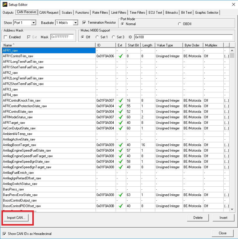
Adding Target Lambda:
- Go the display settings, CAN Receive
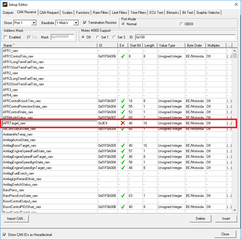
- Find the AFRTarget_Raw row.
- If the Ext shows a green tick, double click the Ext checkbox to force it to the standard 11 bit CAN ID
- Change the CAN ID to 0x3e9
- Start bit = 40, length = 16, unsigned integer, BE/ Motorola
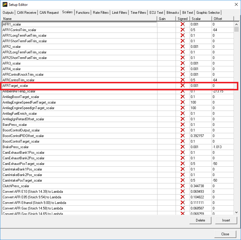
Next go to the Scalars tab, find AFRTarget_scalar and set it to 0.001 with an offset of zero. The Haltech lambda is divided by 1000, so a value of 1000 means stoichiometry.
Using the Adaptronic Native Protocol:
The second method, which is a little bit more work to set up but gives much better control, is to use the Adaptronic native protocol. Rather than try to map all of the Adaptronic variables to the AEM variables, these are just given the same names as in the Adaptronic software.
The way to import them all is to do as follows. First we must clear the existing channels, which will probably be set up for the AEM ECU:
- Go to Setup -> Display
- Select the Outputs tab
- Select the first output name, and click “Delete” at the bottom right, to remove this channel.
- Now that the “Delete” button has the focus, you can hold down the enter key and it will delete all the channels
- Go to the CAN Receive tab
- Again click the top row, and click Delete
- Hold down Enter to delete all the CAN receive channels
- Go to the Scalars tab
- Again click the top row, and click Delete
- Hold down Enter to delete all the CAN receive channels
- Go back to the CAN Receive tab
- Click “Import CAN…”
- Select the appropriate DBC file
The standard DBC files are available in this article. If you have enabled specific other channels to be output, you can also generate the DBC file from the software.
In the standard DBC filenames, the following terms have the following meanings:
- Standard – means that it includes all the channels which are always output from the ECU
- Full – means that it includes all 1024 channels. Some names will be blank and therefore you will get conflict errors when they are imported
The unit scaling is done in the CAN importation because the dash is not unit-aware. The following suffices are used for different unit combinations:
| Filename suffix | AFR / Lambda unit | Pressure unit | Temp and Speed |
| Imperial_AFR | Petrol AFR | PSI | Fahrenheit / mph |
| Imperial_Lambda | Lambda | PSI | Fahrenheit / mph |
| Metric_AFR | Petrol AFR | kPa | Celcius / km/h |
| Metric_AFR_PSI | Petrol AFR | PSI | Celcius / km/h |
| Metric_Lambda | Lambda | kPa | Celcius / km/h |
If you have selected some additional CAN channels to be output in the software, then you can generate a DBC file from the software. When doing this, you must select the output units for scaling for AFR/Lambda, mph / km/h, PSI / kPa and Celcius / Fahrenheit.
DBC Files:
Adaptronic Full Imperial AFR
Adaptronic Full Imperial Lambda
Adaptronic Full Metric AFR
Adaptronic Full Metric AFR PSI
Adaptronic Full Metric Lambda
Adaptronic Standard Imperial AFR
Adaptronic Standard Imperial Lambda
Adaptronic Standard Metric AFR
Adaptronic Standard Metric AFR PSI
Adaptronic Standard Metric Lambda
Big thank you to @Aaparkah.300 – Aaron Parker for lending us the dash for testing.
©2018 Adaptronic