Flex Fuel Tuning on Modular ECU

Since E85 has become commonly available, it has become a popular choice of fuel for performance tuners, because it’s relatively cheap and similar octane level to race fuel. However it’s not available everywhere, and often people with street driven cars, where it is legal to do so with an aftermarket ECU, want to have the option to switch to E0 or any other blend of ethanol and petrol / gasoline. Also, while where I live in Sydney we have E85 at the pump, apparently in the US it’s quite common for “gas stations” to advertise the fuel as E85, but the ethanol content can be as low as 50%, which makes it E50. So if you want to be able to run different fuels without draining the tank, or use “pump E85” in the US, then you need a system that can handle any ethanol percentage in the fuel. This configuration is called “flex fuel” and is supported by all the Modular ECUs, and all the Select ECUs except the base model e420d. This article describes how to set up flex fuel on the Modular ECUs.
Broadly speaking there are three different variables the ECU can change based on the ethanol content, which are the delivered fuel quantity, the ignition timing, and the amount of boost available to the driver.
First let’s discuss how to install such a system on the car. You will need a flex fuel sensor; also called a fuel composition sensor or ethanol sensor. There are three types of these; the old Siemens type, the Continental type and the Ford type. We do not support the Ford type, but the Continental and the Siemens have the same output configuration and we support both of those.

This can either be connected in series with the supply side, or the return side of the fuel going back to the tank. In some cases people do things like loops to make sure that the sensor stays wet even when the fuel drains away, or run parallel paths so it’s not a restriction to the fuel delivered to the engine, or even put the sensor in the return path from a surge tank back to the main tank. There are various arguments about this and if you want to start an argument on the internet, go to a facebook group with a bunch of tuners and tell them the right way to do it.
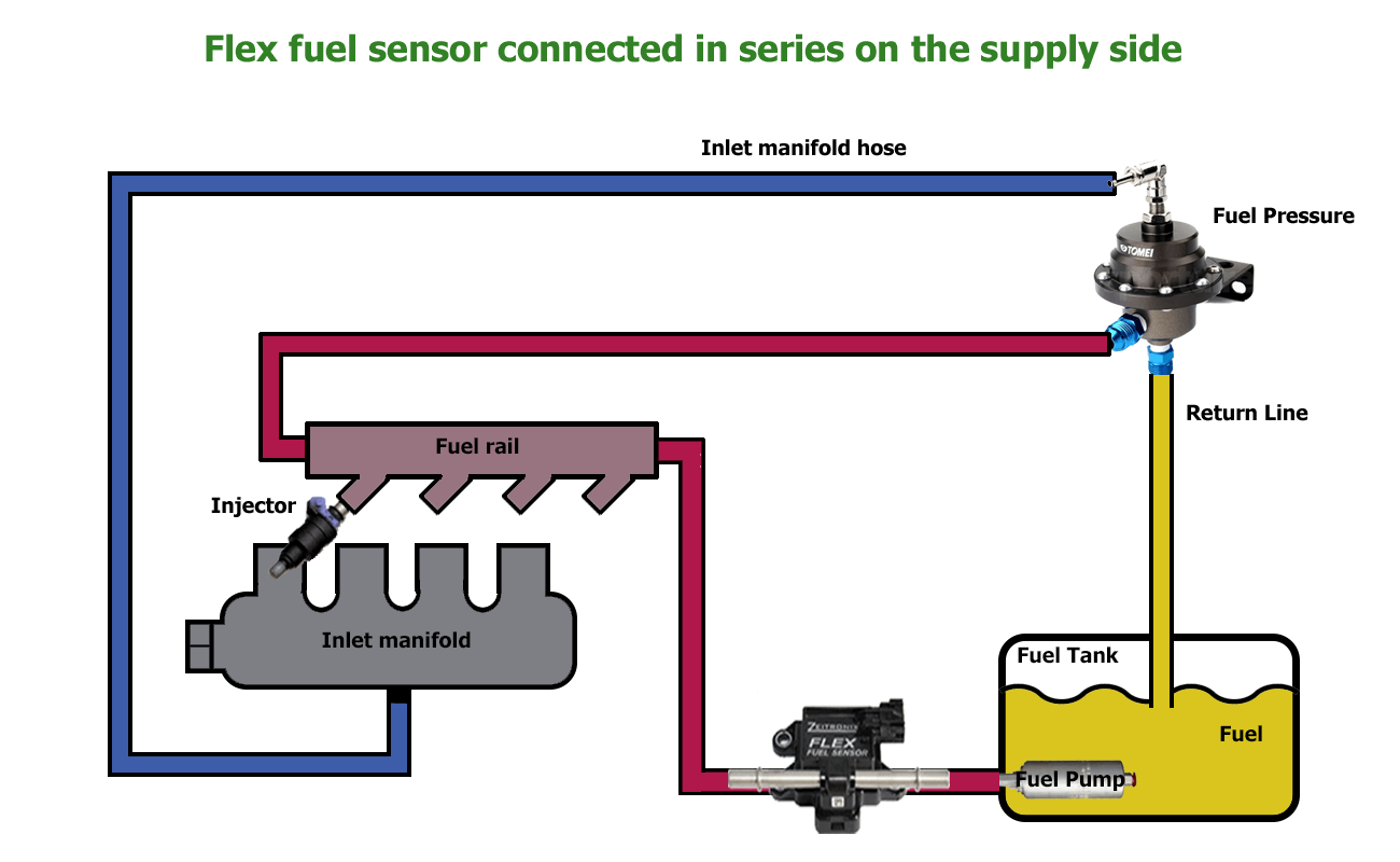
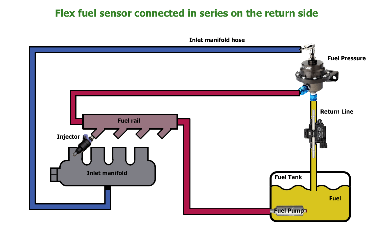
One argument against using the return from the regulator is that if you run out of fuel supply and the regulator shuts off completely, then the sensor will be dry and that will give an incorrect reading. The Modular ECUs mitigate against this by only reading the value from the sensor when the engine is in the vacuum condition; as soon as the engine develops boost, the ECU “locks” the value until it gets on vacuum again.
One argument against using the sensor on the supply side is that it’s another potential point of failure on the pressurised part of the fuel system, but OEMs do this and obviously they have assessed the risks. A second reason not to use the sensor on the supply side is that it might cause a restriction and therefore a fuel pressure drop. If you’re worried about this you can always measure the fuel pressure drop across the sensor; and I expect that it will be less of a restriction than you think it will.
The one thing I’ll say about having the sensor between the surge tank and the main tank is that one of the benefits of using such a sensor is that it reports not only the ethanol percentage, but also the fuel temperature. The ECU can use the fuel temperature to make corrections based on the fuel density change with temperature, and we highly recommend this, especially with E85 fuel. Some cars have fuel temperature sensors fitted from the factory, for example the FD RX7 and the Z32 300ZX, and ethanol’s density changes with temperature more quickly that petrol’s density does. So we do recommend measuring fuel temperature, and it makes sense to do that with the ethanol sensor because it saves adding more components and wiring. If you do want to run the flex sensor at the back of the car though, and a separate fuel temperature sensor, you can do that.
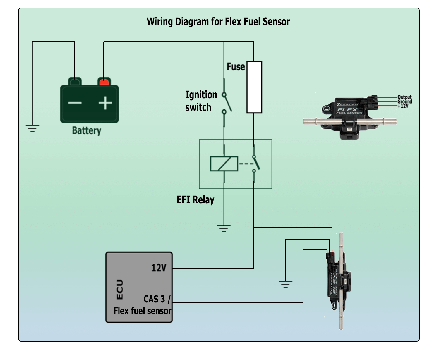
As far as wiring goes, the flex sensor needs 12V ignition switched power, ground and it has a signal output. In most cases you can connect this to the CAS3 input on the ECU, because most fixed valve timing and many variable valve timing engines have only 2 crank or cam angle sensors. If you do need to use 3 CAS inputs or more with flex fuel, then you will need to upgrade the ECU with the Mini Realtime input module, which gives you another 2 CAS inputs, 3 vehicle speed inputs and a dedicated flex input.
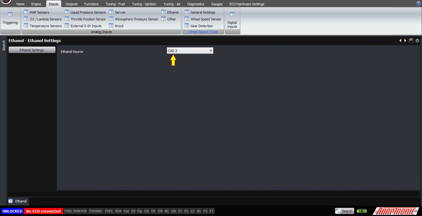
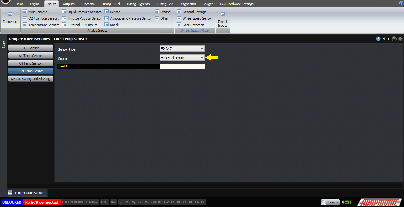
Once you’ve done that, go to the ethanol input setup and select the source as being “CAS3”. To measure fuel temperature from the same sensor, go to Inputs -> Temperature sensors -> fuel temperature. Select the type as any calibration and the source as “from flex sensor”.
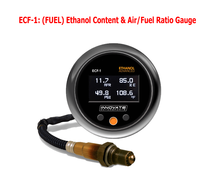
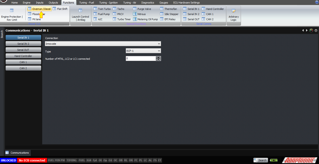
The other way to get the ethanol content into the ECU is to use the Innovate ECF-1 gauge. This gives ethanol content, fuel temperature and lambda over one connection. To configure this, firstly go to the setting for the serial port you will use (serial 1 or serial 2) and select the “connection” as “Innovate”. Select the type as “ECF-1”, and select the number of MTXL, LC1 or LC2 as being zero.
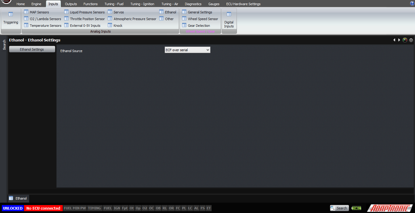
Then go to the Inputs -> Ethanol and select the source as ECF over serial. The setting for the fuel temperature sensor remains the same.
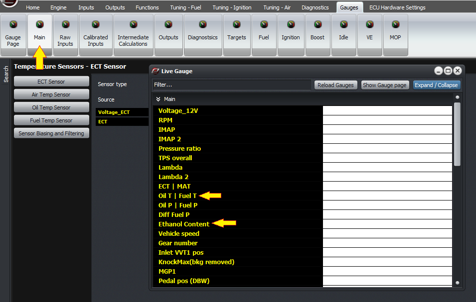
Before doing any flex tuning, you should do what we always say to do and verify that the sensor is reading correctly. The ethanol percentage and fuel temperature are both shown in the main gauges area so you can check them easily.
If it doesn’t display, then check the configuration as I described above. If it’s connected directly through CAS3, then verify that the CAS3 ARM on the F11 window flashes between red and grey.
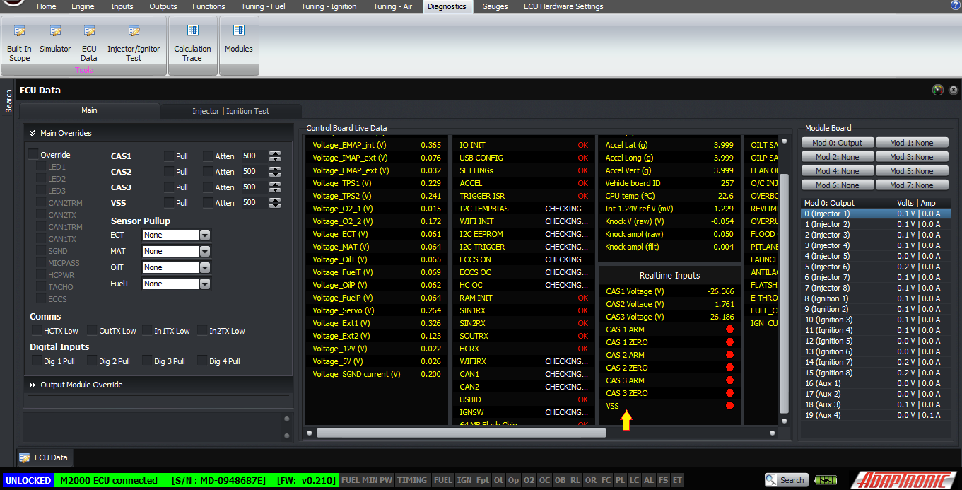
If it’s stuck at red, that means that either the sensor does not have power, or that the signal wire is shorted to ground. If it’s stuck at grey, that means either that the sensor does not have power or that there’s an open circuit in the connection between the sensor and the ECU. You can verify that the wiring and the ECU are working correctly by unplugging the sensor and shorting the sensor output pin on the connector to ground, and verify that the ARM goes from grey to red when you do that. Please remember that just like many other components, there are counterfeit sensors around which have had early life failures.
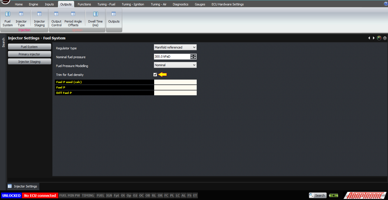
OK, assuming that the sensor is reading correctly, let’s look at the settings required to set it up correctly. Firstly, we highly recommend enabling the “trim for fuel density” setting in Outputs -> Fuel System. This causes the ECU to calculate the fuel density based on the measured fuel temperature and also the ethanol percentage, and use that to convert the fuel mass calculation into a volume, to calculate the injector duration required.
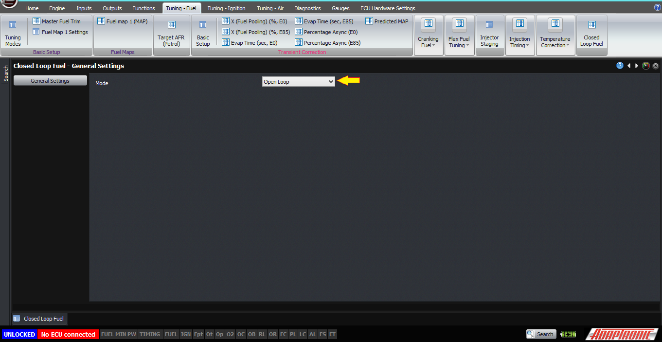
Next, for the fuel map that you’re using (we’ll assume you’re using fuel map 1), we need to change the Stoich source from “constant” to “flex fuel”. This means that instead of using a fixed stoichiometric ratio, the ECU will look at the ethanol percentage from the sensor and calculate the stoichiometric ratio from that. The stoich value will be the value that the ECU will use in the event of a sensor failure, so for example if your normal fuel is E85 then you would put 10.0 in this setting.
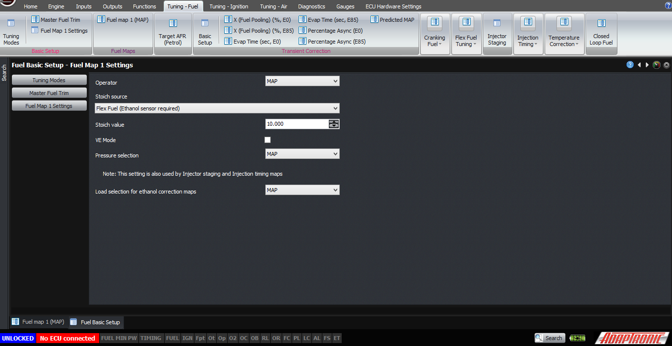
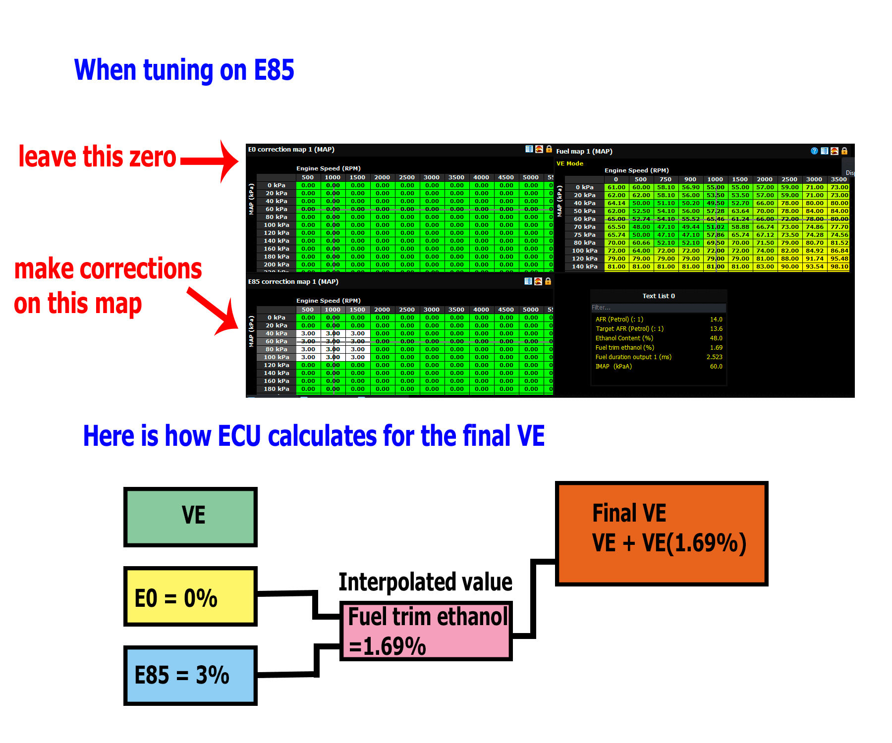
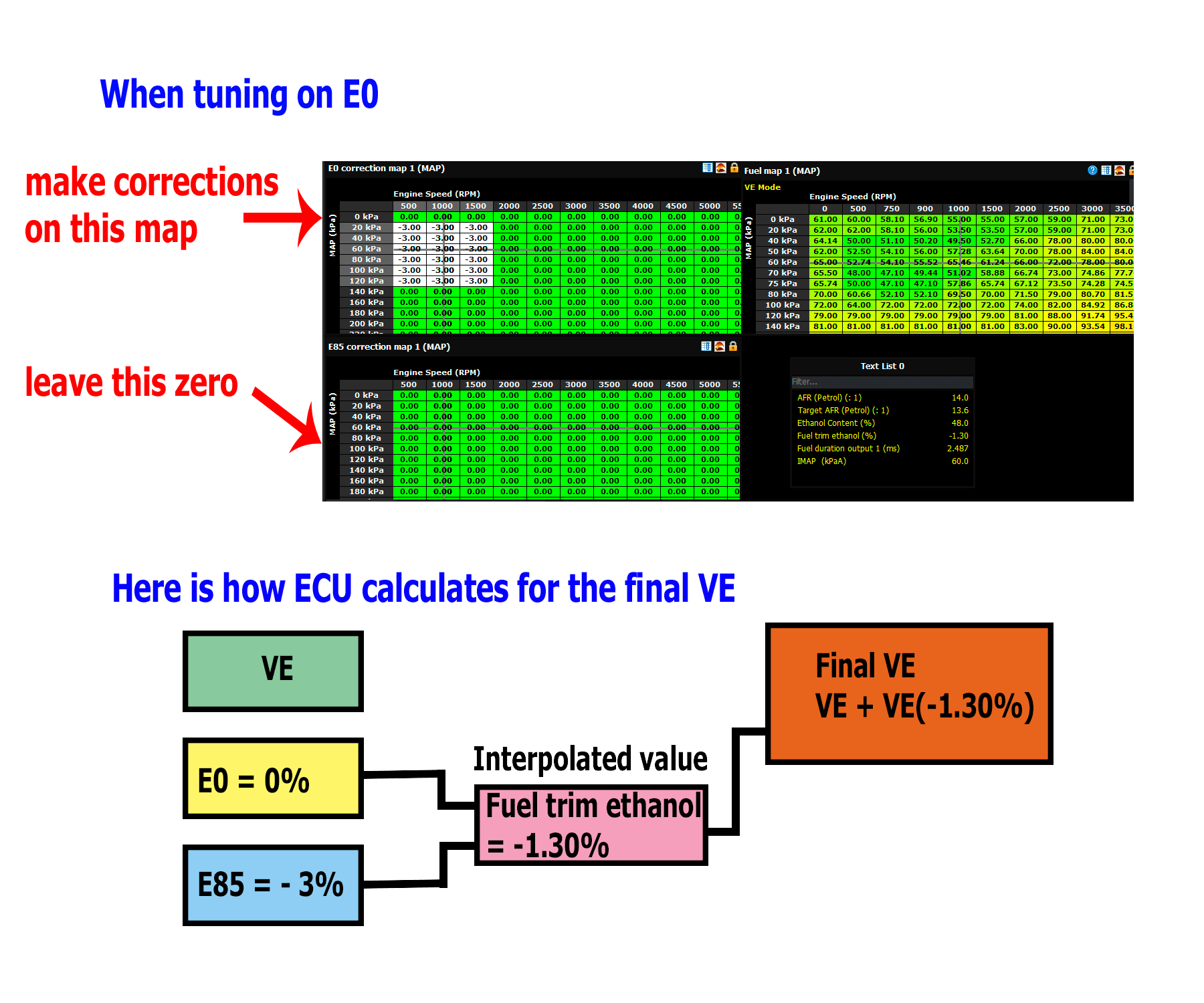
The way the fuel calculation works is that you have three tables. You have the basic VE table, the same as if you were doing a fixed-fuel tune. Then there is a correction table for 0% ethanol, and a second correction table for 85% ethanol. The ECU interpolates between these two tables and uses this to trim the main fuel map.
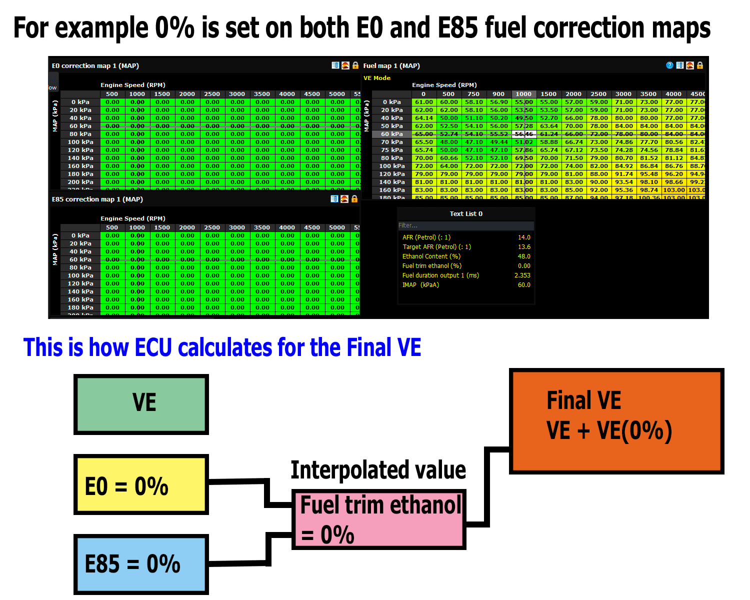
The first step is to then set both E0 and E85 maps to zero.Then tune the first fuel on the main map.
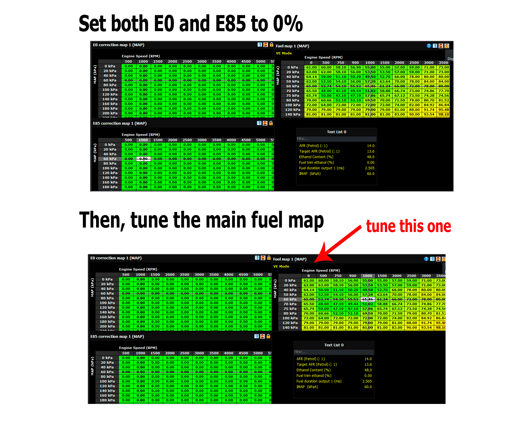
Then switch to the second fuel, and modify the correction map for that fuel so that the lambda is still correct with the new fuel. In theory this map should be zero everywhere; in practice the maps tend to be in the range of ±5% usually. This method allows you to either tune E0 or E85 first.
For ignition timing, the same process occurs where you have the main ignition map, and then an E0 and an E85 correction map. If you use the E85 condition as the default condition, then the E85 map will be zero and the E0 map will have negative values in it to pull out timing at the lower ethanol percentage.
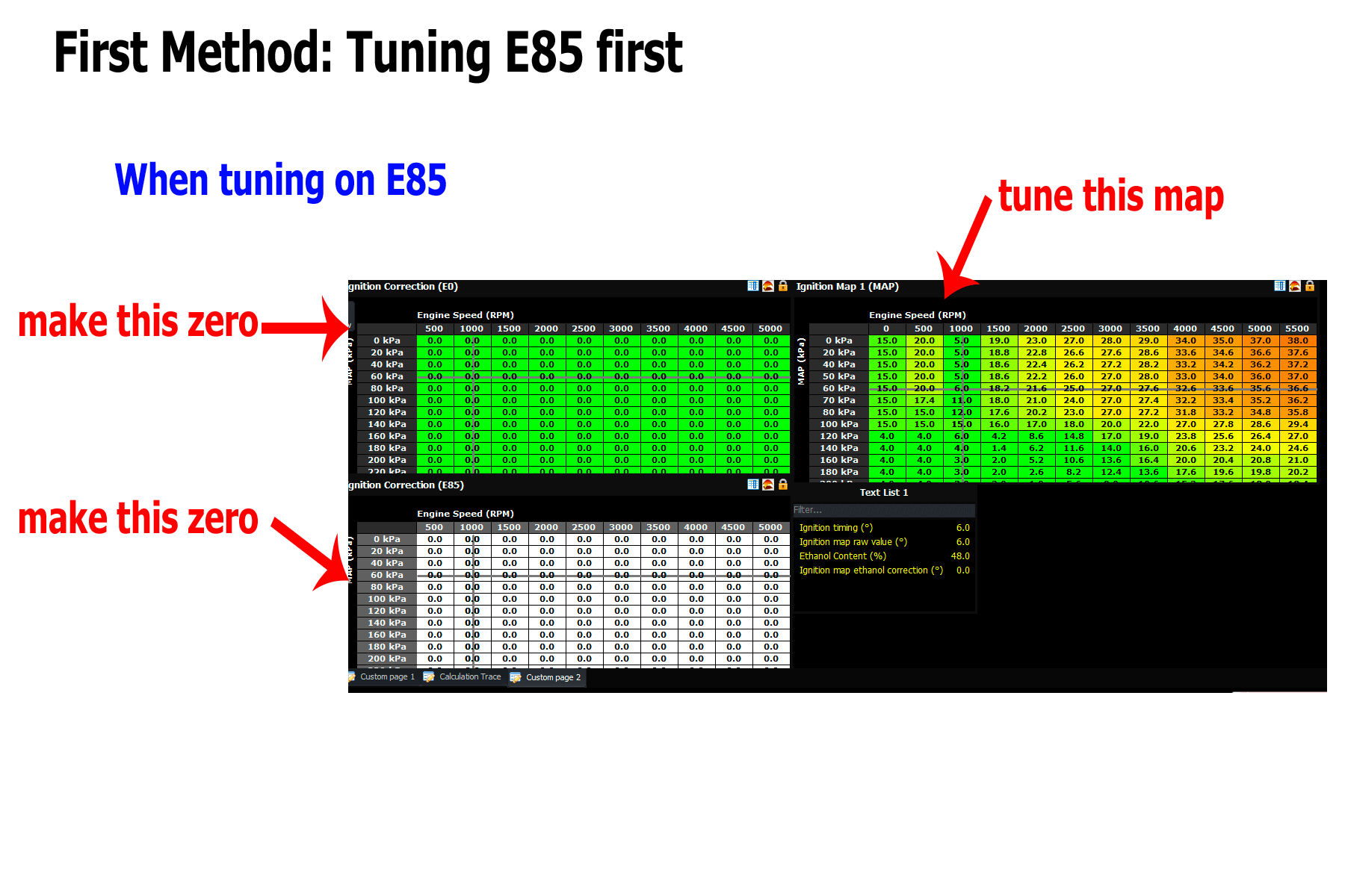
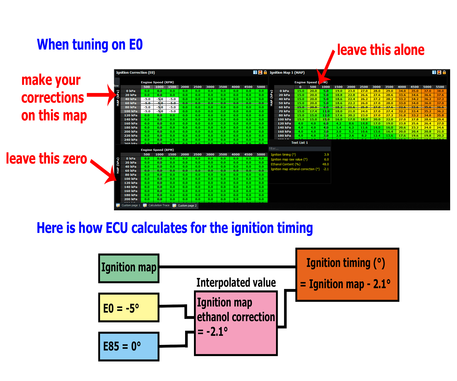
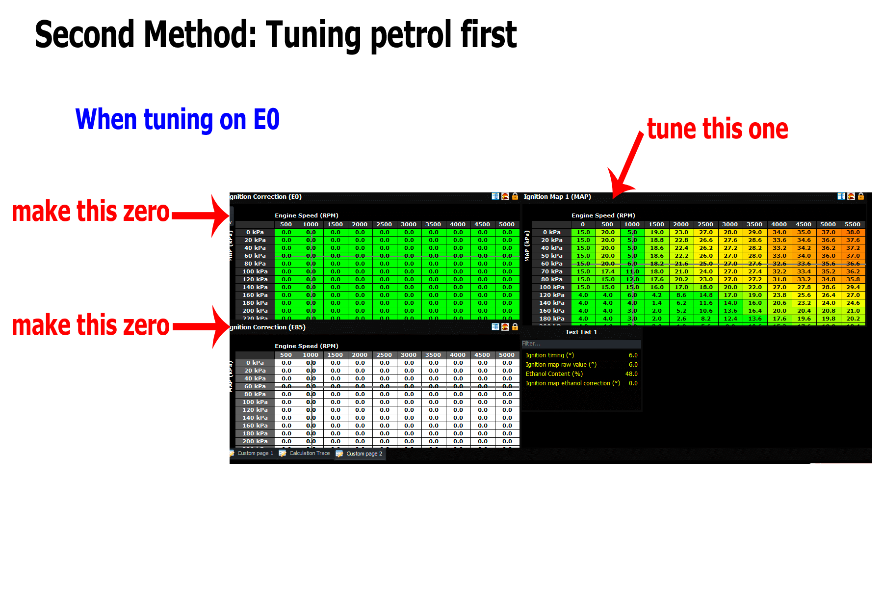
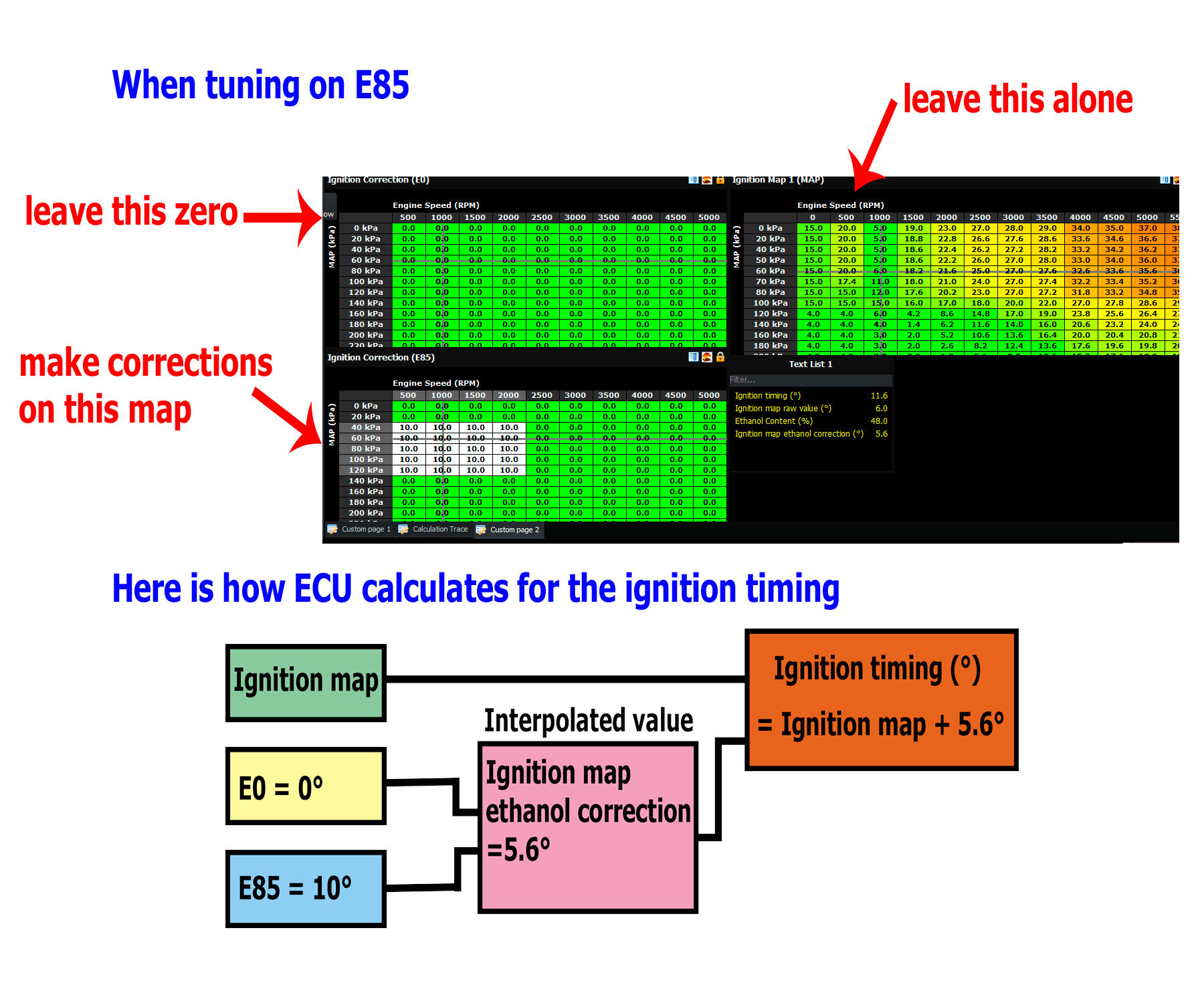
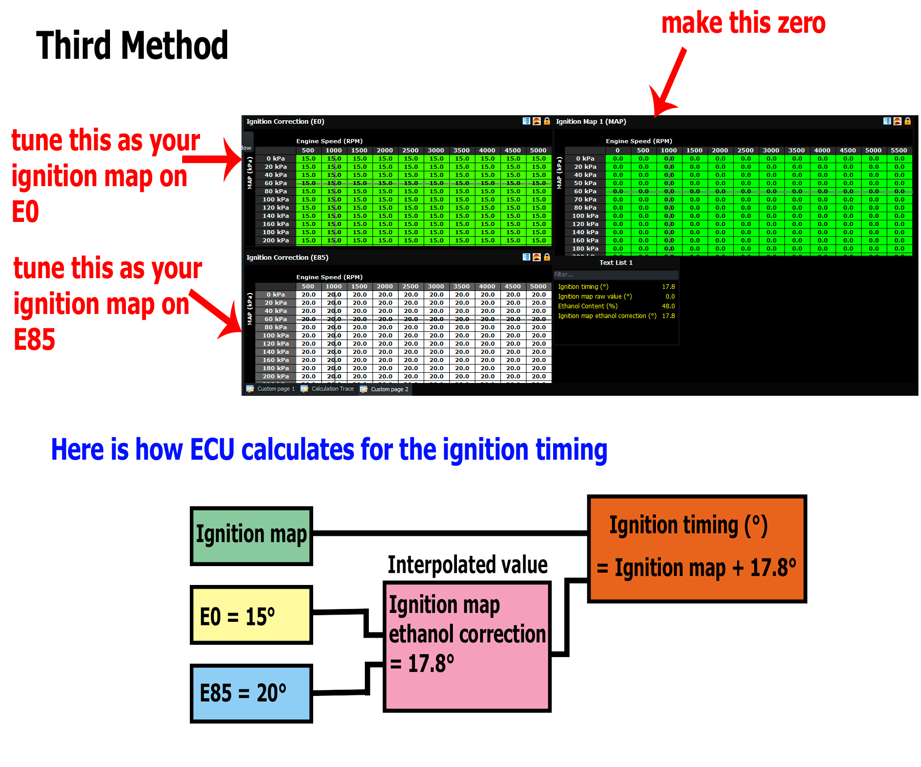
There is a third way that you can do ignition timing, because the timing values are added – and that is to leave the main ignition map at zero, and then you can treat the E0 map as the ignition map for no ethanol, and the E85 correction map can be your ignition map for E85. The downside is that the ignition correction maps are only 15×15 in size instead of the main ignition map which is 31 x 31 but in practice I don’t think this would be a limitation.
The final behaviour that can be affected by ethanol percentage is boost. To enable this, go to the boost settings page and select “limits”. Enable the “limit boost by ethanol content” checkbox, and then select the limit vs ethanol content. If you are in open loop, duty cycle mode, then this table is a duty cycle limit for the wastegate actuator based on the ethanol percentage. If you are in a target boost mode, then these values become the new lower target boost when the ethanol content is lower. Obviously the target boost or duty cycle limit has to be higher than what you intend to run at E85 at the 85% point, otherwise it will limit your boost.
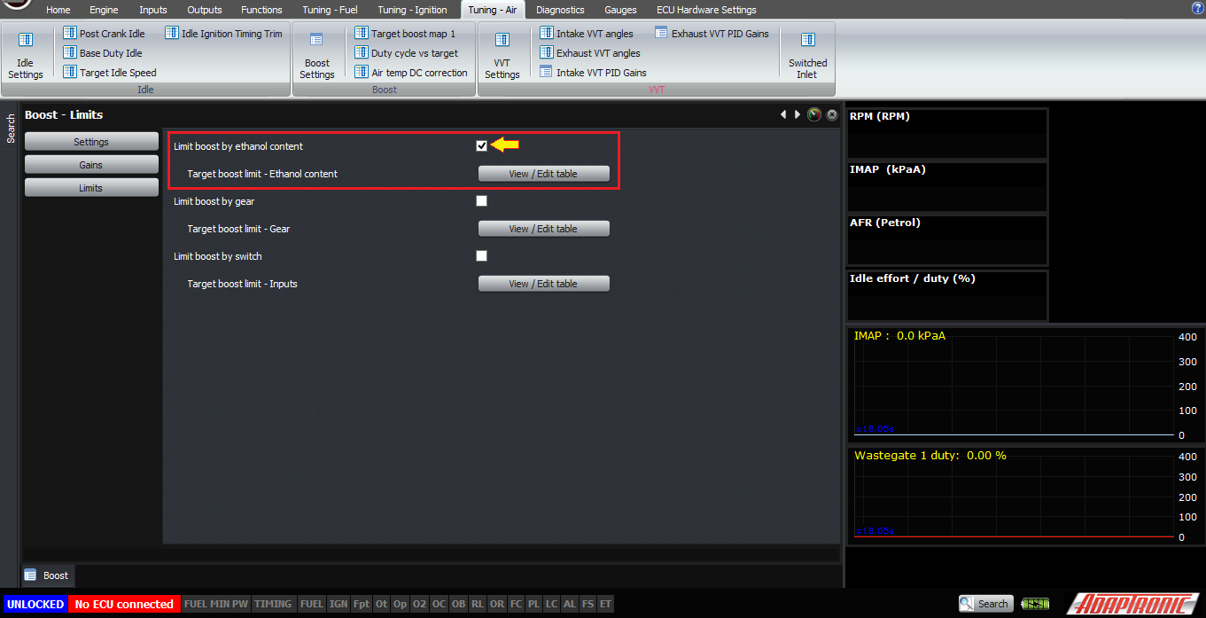
Also obviously when testing boost limit based on ethanol, remember that other limits might be applying at the same time, for example gear and external boost selection inputs.
One final point about flex fuel, the ECU “thinks” in lambda rather than AFR. The AFR is only calculated as an intermediate step in working out the fuel quantity from the air quantity. So to avoid confusion and delay, we recommend displaying lambda and using lambda targets, because firstly that’s what the engine really cares about (that is, whichever fuel you’re running, the target lambda is usually approximately the same, certainly between ethanol and petrol) and secondly that’s what the lambda sensor actually measures. If you ask the software to display it as AFR instead of lambda, it displays what we call “petrol AFR” which is lambda multiplied by 14.7. This will not be the correct AFR unless your stoichiometric ratio is 14.7. However, it seems that almost all lambda sensors display lambda in this way by default if not exclusively, and that also includes the lambda / AFR displays on dynos.
Thank you very much!
©2018 Adaptronic