P0846-2C PRESSURE SWITCH RATIONALITY


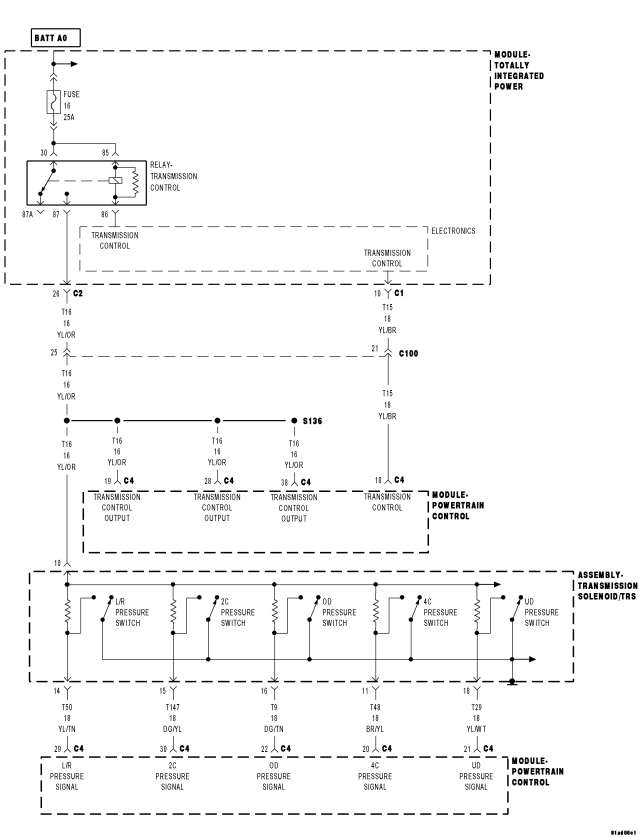
For a complete wiring diagram Refer to Section 8W

Theory of Operation


The Transmission system uses five pressure switches to monitor the fluid pressure in the L/R, 2C, 4C, UD, and OD clutch circuits. The pressure switches are continuously monitored for the correct states in each gear as shown.


Possible Causes
RELATED TIPM TCM DTCS PRESENT
(T147) 2C PRESSURE SWITCH SENSE CIRCUIT OPEN
(T147) 2C PRESSURE SWITCH SENSE CIRCUIT SHORT TO GROUND
(T147) 2C PRESSURE SWITCH SENSE CIRCUIT SHORT TO OTHER CIRCUITS
EXCESSIVE FLUID LEAKAGE IN 2C CLUTCH CIRCUIT
NO. 5 AND/OR NO. 7 CHECK BALL CUT OR DAMAGED
EXTRA CHECK BALL DOWNSTREAM OF THE NO. 7 CHECK BALL SOCKET
LOW LINE PRESSURE
TRANSMISSION SOLENOID/TRS ASSEMBLY
POWERTRAIN CONTROL MODULE
WIRING AND CONNECTORS


Always perform the 45RFE/545RFE Pre-Diagnostic Troubleshooting Procedure before proceeding. (Refer to 21 - TRANSMISSION/TRANSAXLE/AUTOMATIC - 45RFE/545RFE - STANDARD PROCEDURE)


GEAR
L/R
2C
4C
UD
OD
REVERSE
OPEN
OPEN
OPEN
OPEN
OPEN
P/N
CLOSED**
OPEN
OPEN
OPEN
OPEN
1ST
CLOSED*
OPEN
OPEN
CLOSED
OPEN
2ND
OPEN
CLOSED
OPEN
CLOSED
OPEN
2nd PRIME
OPEN
OPEN
CLOSED
CLOSED
OPEN
3TH
OPEN
OPEN
OPEN
CLOSED
CLOSED
4TH
OPEN
OPEN
CLOSED
OPEN
CLOSED
5TH
OPEN
CLOSED
OPEN
OPEN
CLOSED
*L/R is closed if output speed is below 100 rpm in Drive and Manual 2. L/R is closed in Manual 1.
**May be open when rolling in Neutral or at low oil temperatures.


Diagnostic Test

1. CHECK FOR TCM TIPM DTCS

With the scan tool read DTCs.

Are there any TIPM TCM Power Control Circuit or TCM Power Input DTCs present?

Yes


No

2. CHECK IF THE DTC DATA SHOWS THE CURRENT DTC

With the scan tool, check the DTC EVENT DATA.

Does the DTC EVENT DATA show data for DTC P0846?

Yes


No

3. CHECK IF MULTIPLE DTCS ARE PRESENT

With the scan tool, check DTCs.

Are there two or more related pressure switch rationality DTCs present in addition to P0846?

Yes


No

4. CHECK IF ALL THE PRESSURE SWITCHES READ CLOSED

With the scan tool, check the DTC EVENT DATA for P0846.

NOTE: Make sure to record all DTC EVENT DATA stored in the scan tool for future reference in this test procedure.


Do all the pressure switches read CLOSED in the DTC EVENT DATA for P0846?

Yes


No

5. CHECK IF ALL THE PRESSURE SWITCHES READ OPEN

In the DTC EVENT DATA recorded earlier, read the state of all pressure switches.

Do all the pressure switches read OPEN?

Yes


No

6. CHECK FOR LOW LINE PRESSURE

In the DTC EVENT DATA recorded earlier, compare the Line Pressure and the Desired Line Pressure.

Is the Line Pressure less than 40 psi, and significantly below the Desired Line Pressure?

Yes


No

7. CHECK IF THE DTC SET IN PARK, NEUTRAL, OR REVERSE

With the scan tool, check the DTC EVENT DATA for P0846.

NOTE: Make sure to record all DTC EVENT DATA stored in the scan tool for future reference in this test procedure.


Does the DTC EVENT DATA show the DTC P0846 set in Park, Neutral, or Reverse?

Yes


No

8. CHECK IF THE 2C PRESSURE SWITCH READS CLOSED

With the scan tool, check the DTC EVENT DATA for P0846.

Does the DTC EVENT DATA show the 2C Pressure Switch reading CLOSED?

Yes


No

9. CHECK THE LINE PRESSURE

In the DTC EVENT DATA recorded earlier, compare the Line Pressure and the Desired Line Pressure.

Is the Line Pressure less than 40 psi, and significantly below the Desired Line Pressure?

Yes


No

10. CHECK THE PCM AND WIRING

Turn the ignition off to the lock position.
Remove the Ignition Switch Feed fuse from the TIPM.

CAUTION: Removal of the Ignition Switch Feed fuse from the TIPM will prevent the vehicle from being started in gear.


WARNING: The Ignition Switch Feed fuse must be removed from the TIPM. Failure to do so can result in personal injury or death.


Install the Transmission Simulator, Miller tool #8333.
Ignition on, engine not running.
With the Transmission Simulator, turn the Pressure Switch selector switch to the 2C position.
With the scan tool, monitor the 2C Pressure Switch while pressing the Pressure Switch test button on the Transmission Simulator.

Did the state of the 2C Pressure Switch change while pressing the Pressure Switch Test button?

Yes


No

11. CHECK THE TRANSMISSION SOLENOID/TRS ASSEMBLY

Using the schematics as a guide, inspect the wiring and connectors specific to this circuit.
Wiggle the wires while checking for shorted and open circuits.

Where there any problems found?

Yes


No

12. CHECK THE (T147) 2C PRESSURE SWITCH SENSE CIRCUIT FOR AN OPEN


Turn the ignition off to the lock position.
Disconnect the Transmission Simulator, Miller tool #8333.
Disconnect the PCM C4 harness connector.
Connect Miller tool #8815 to the PCM C4 harness connector.

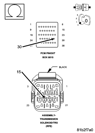
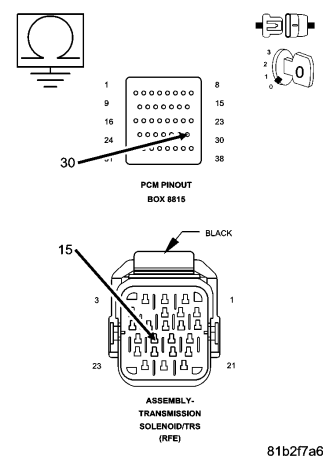
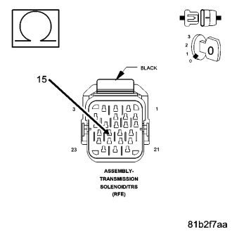
CAUTION: Do not probe the PCM harness connectors. Probing the PCM harness connectors will damage the PCM terminals resulting in poor terminal to pin connection. Install Miller tool #8815 to perform diagnosis.


Measure the resistance of the (T147) 2C Pressure Switch Sense circuit between the Transmission Solenoid/TRS Assembly harness connect and the appropriate terminal of Miller tool #8815.

Is the resistance above 5.0 ohms?

Yes


No

13. CHECK THE (T147) 2C PRESSURE SWITCH SENSE CIRCUIT FOR A SHORT TO GROUND


Measure the resistance between ground and the (T147) 2C Pressure Switch Sense circuit.

Is the resistance below 5.0 ohms?

Yes


No

14. CHECK THE (T147) 2C PRESSURE SWITCH SENSE CIRCUIT FOR A SHORT TO ANOTHER CIRCUIT


Measure the resistance between the (T147) 2C Pressure Switch Sense circuit and all the other circuits in the Transmission Solenoid/TRS Assembly harness connector.

Is the resistance below 5.0 ohms?

Yes


No

15. CHECK IF THE #5 AND/OR #7 CHECK BALL IS CUT OR DAMAGED

Turn the Ignition off to the lock position.
Remove the Valve Body Assembly per the Service Information.
Inspect the #5 and #7 check balls for any cuts or damage.
Check for an extra check ball in the passage downstream from the #7 check ball pocket.
Inspect the 2C accumulator piston and seals and also the 2C tower seal on top of the valve body. Refer to the Service Information.

Where there any problems found?

Yes


No

16. CHECK FOR EXCESSIVE FLUID LEAKAGE WITHIN THE 2C CLUTCH CIRCUIT

Air check the 2C Clutch hydraulic circuit. Refer to the Service Information.

NOTE: This hydraulic clutch circuit contains a small bleed orifice. Small leakage is considered normal.


Was there excessive air leakage in the 2C Clutch hydraulic circuit?

Yes


No