
For a complete wiring diagram Refer to Section 8W.
Ignition on and battery voltage above 10.4 volts.
The fuel level sensor signal voltage goes below 0.4 of a volt for more than 90 seconds. One Trip Fault. Three good trips to turn off the MIL.
|
Possible Causes
|
|
(N4) FUEL LEVEL SIGNAL CIRCUIT SHORTED TO GROUND |
|
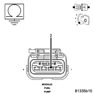
(N4) FUEL LEVEL SIGNAL CIRCUIT SHORTED TO THE (K900) SENSOR GROUND CIRCUIT |
|
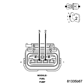
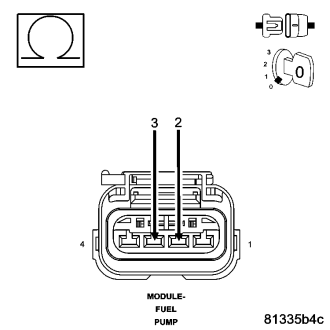
FUEL LEVEL SENSOR |
|
TIPM |
Always perform the Pre-Diagnostic Troubleshooting procedure before proceeding. (Refer to 9 - ENGINE - DIAGNOSIS AND TESTING)
NOTE: Diagnose any CAN - B or CAN -C Communication DTCs before continuing.
NOTE: Before continuing, check the TIPM harness connector terminals for corrosion, damage, or terminal push out. Repair as necessary.