Delatrons are counting tubes. Nominally base-10 (dekatron), however base 5 and 20 are also common. With each pulse input trigger (sometimes leading edge sometimes trailing edge - sometimes both lead and trailing edge pulses) the dekatron will change state - by placing dekatrons serially, such that each dekatron forms the input to the next we can create a simple pulse counter such as in my dekatron counter (which was also implemented with my artificial dekatrons). The drawback of actual dekatron tubes are the high voltages necessary for their operation, 250 - 280 Volts. Rather than work with actual dekatron tubes, I decided to create my own artificial dekatrons from dispay case light bulbs and orange LEDs.
You start with a incandescent dispay case light bulb which has been continuously lighted until it has burned out. This deposits a nice dark layer of tungsten on the interior of the bulb. |
 |
 |
Wrap the bulb in scotch tape, and mark with a sharpie. Then carefully use a Dremel tool abrasive wheel to weaken the glass and cut the end from the bulb. |
I designed my own circuit board which I had fabricated by Express PCB. These are the components used in constructing the LCD display in the artificial dekatron. |
 |
 |
With the resisters soldiered on the board. |
All the components soldiered on the board. |
 |
 |
Leads attached to the back of the board. Red leads are for LED anodes, white are LED cathodes. The board is divided into quarters, each quarter has a common cathode to the 5 LEDS in that quarter of the board/display. Each of the 5 LEDS share the same anode with their counterparts in the other quarters of the display. In this way, each LED can be individually lighted with 9 leads to the board; selectively applying a ground (to a cathode lead ) and Vdd (to an anode lead). |
Last step is to use E6000 to glue the board into the bulb. |
 |
 |
Close up of Lilypad Arduino microprocessor board in the Dekatron spinner box. |
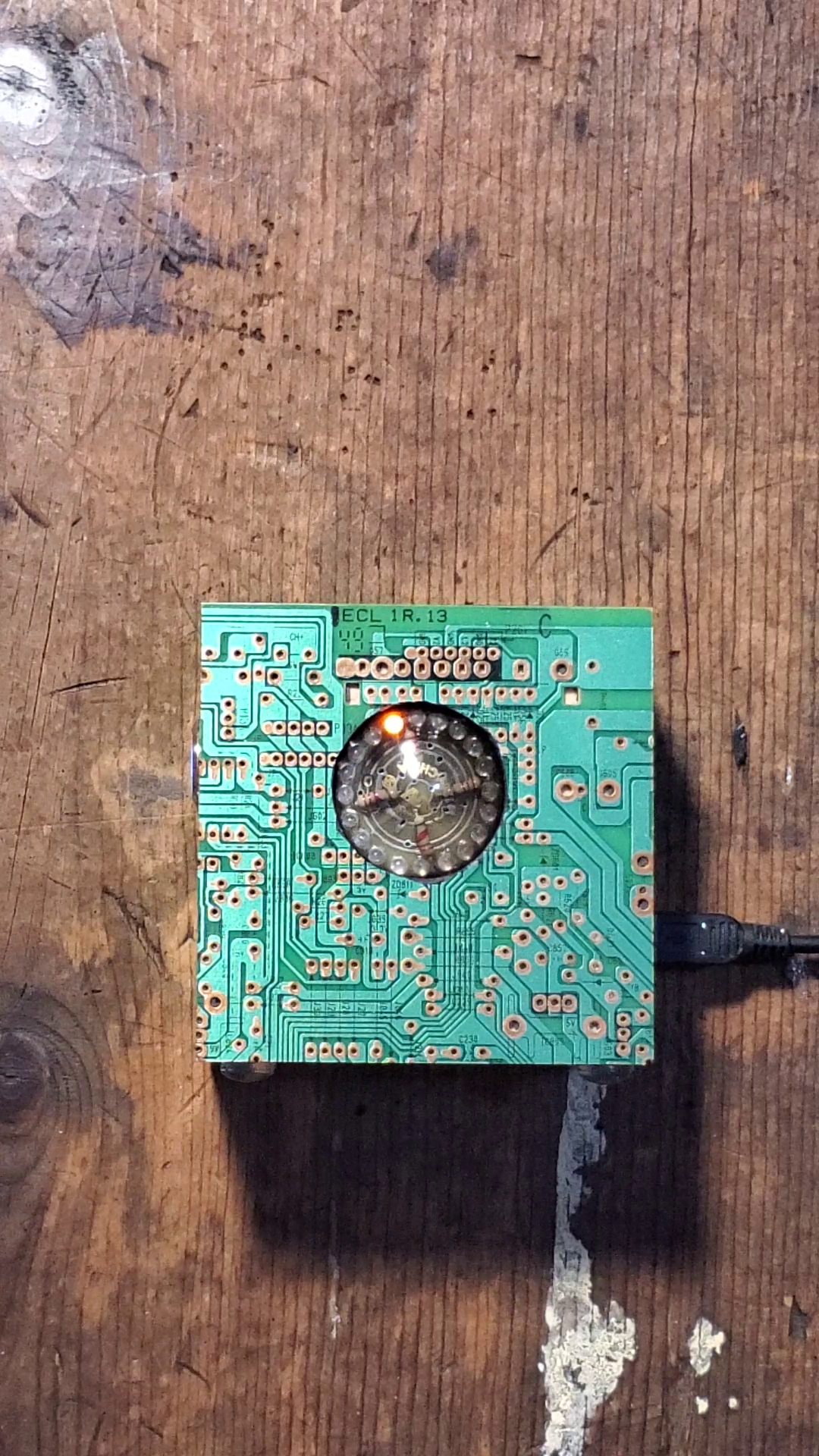
Finished Dekatron Spinner - in circuit card box. |
 |
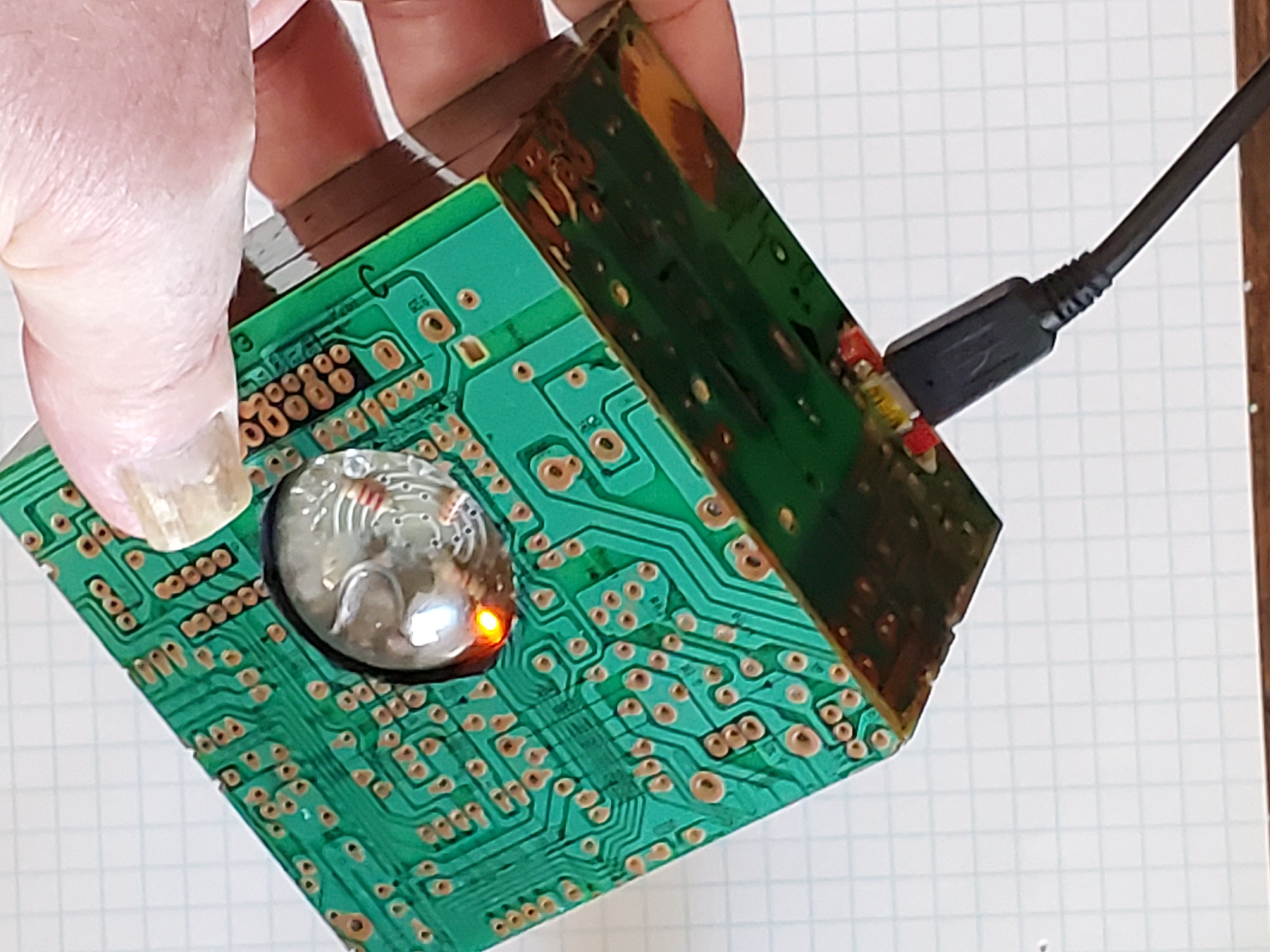 |
Another View of the Dekatron Spinner |
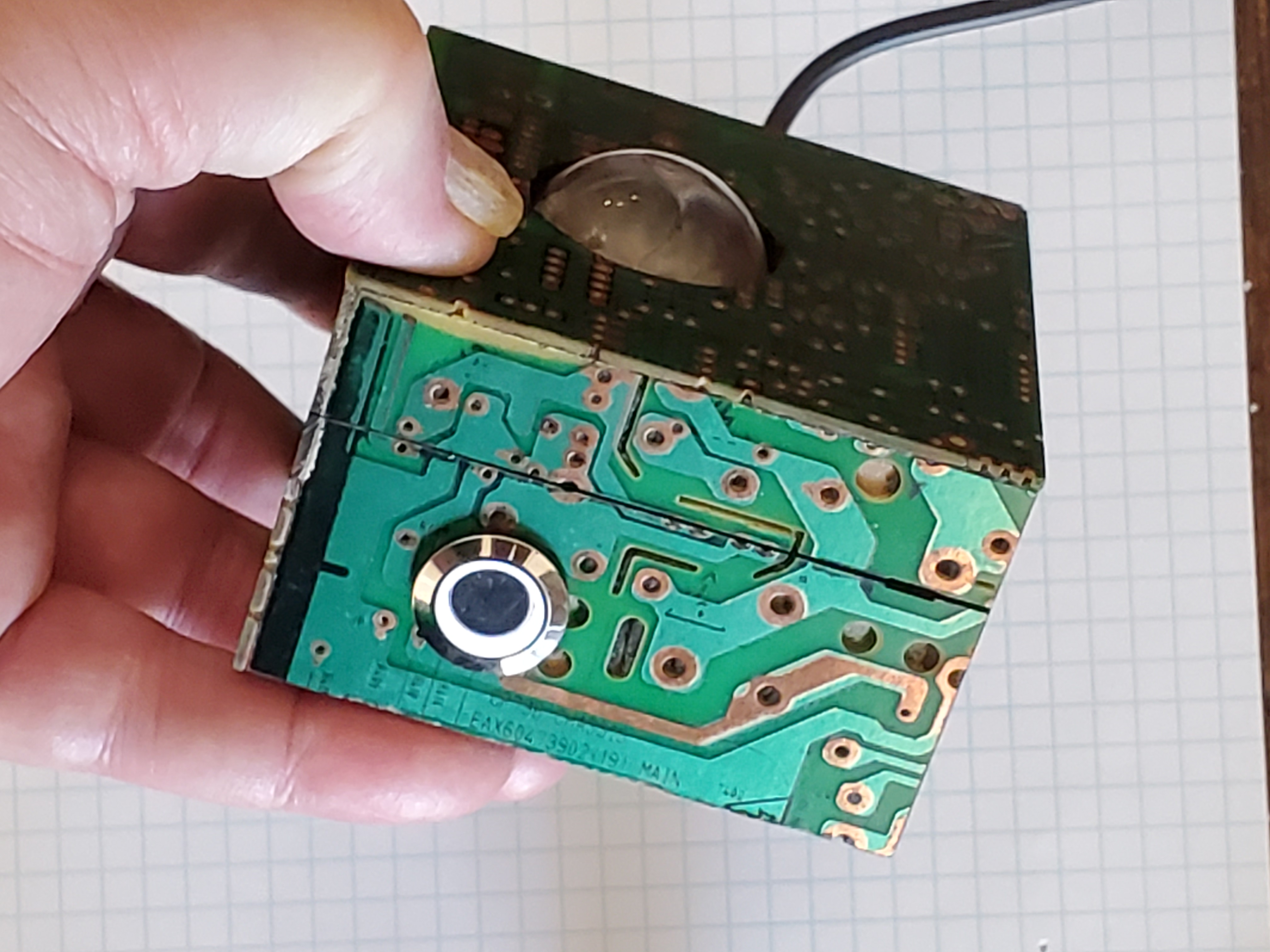
View of lighted pushbutton on/off switch. |
 |
 |
Movie showing spinner features - variable speed both clockwise and counterclockwise and push button reset - using a digital encoder with Arduino interupts. |